Technical Background
Page 23
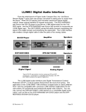
... Protection (DTCP), a robust system that on the SCD-XA9000ES SA-CD/CD player and the DVPNS9100ES DVD/SA-CD/CD player. ES Receivers v1.0 Page 23 The i.LINK interface also enables a single digital cable to a compatible SA-CD player, the STRDA7100ES maintains the signal ...interface to digital audio is clearly different from piracy. While SA-CD players have included coaxial and optical digital outputs, these outputs handled CD signals exclusively. And the STR-DA9000ES was Sony's first receiver to a compatible digital audio output, such as that protects the music from -and not compatible with...
... Protection (DTCP), a robust system that on the SCD-XA9000ES SA-CD/CD player and the DVPNS9100ES DVD/SA-CD/CD player. ES Receivers v1.0 Page 23 The i.LINK interface also enables a single digital cable to a compatible SA-CD player, the STRDA7100ES maintains the signal ...interface to digital audio is clearly different from piracy. While SA-CD players have included coaxial and optical digital outputs, these outputs handled CD signals exclusively. And the STR-DA9000ES was Sony's first receiver to a compatible digital audio output, such as that protects the music from -and not compatible with...
Technical Background
Page 36
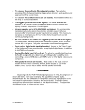
...with third-party room automation systems, these receivers also accept optical digital audio, in the home theater room and still control your components. • RS-232C interface for control and upgrade (STR-DA2100ES and higher). ES Receivers v1.0 Page 36 This means you can... be used in 1982, the engineers of Sony's ES Series have been extending the capabilities of modern A/V receivers...
...with third-party room automation systems, these receivers also accept optical digital audio, in the home theater room and still control your components. • RS-232C interface for control and upgrade (STR-DA2100ES and higher). ES Receivers v1.0 Page 36 This means you can... be used in 1982, the engineers of Sony's ES Series have been extending the capabilities of modern A/V receivers...
Technical Background
Page 37
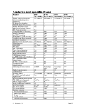
ES Receivers v1.0 Page 37 Yes Yes Yes IIx Yes Yes 7.1-channel Yes Yes (Two) Yes Yes Yes Yes 7.1 -/2/1 5/2 5/2 To Component 5/2 2 7.1 channels Yes 1/2 Yes/Yes 3 3/3 A/V out Audio ... i.LINK® digital audio interfaces HD Component video inputs/output S-Video inputs/outputs Composite video inputs/outputs Video Upconversion (best) Optical inputs/outputs Coaxial inputs Preamp output Front A/V input with optical digital audio Infrared repeater input/outputs RS-232C control/upgrade 12-volt trigger outputs Multi-Zone/Room Capability 2nd Room output...
ES Receivers v1.0 Page 37 Yes Yes Yes IIx Yes Yes 7.1-channel Yes Yes (Two) Yes Yes Yes Yes 7.1 -/2/1 5/2 5/2 To Component 5/2 2 7.1 channels Yes 1/2 Yes/Yes 3 3/3 A/V out Audio ... i.LINK® digital audio interfaces HD Component video inputs/output S-Video inputs/outputs Composite video inputs/outputs Video Upconversion (best) Optical inputs/outputs Coaxial inputs Preamp output Front A/V input with optical digital audio Infrared repeater input/outputs RS-232C control/upgrade 12-volt trigger outputs Multi-Zone/Room Capability 2nd Room output...

Operating Instructions
Page 8
... 10-11 13-14 10-11 11 or 14 16 10-11 10-11 12 13 15 12 15 15 13 16 *1 Model with a DIGITAL OPTICAL OUTPUT or DIGITAL COAXIAL OUTPUT connector, etc. *2 Model with component video (Y, B-Y, R-Y) input jacks. 8GB Getting Started 1: Check how to hookup your ...components Steps 1a through this receiver. This connection is used to output the audio decoded by the component's internal multi-channel decoder through 1c beginning on page 10 describe how to...
... 10-11 13-14 10-11 11 or 14 16 10-11 10-11 12 13 15 12 15 15 13 16 *1 Model with a DIGITAL OPTICAL OUTPUT or DIGITAL COAXIAL OUTPUT connector, etc. *2 Model with component video (Y, B-Y, R-Y) input jacks. 8GB Getting Started 1: Check how to hookup your ...components Steps 1a through this receiver. This connection is used to output the audio decoded by the component's internal multi-channel decoder through 1c beginning on page 10 describe how to...

Operating Instructions
Page 9
and red (right, audio) to red. • When connecting optical digital cords, insert the cord plugs straight in until they click into two monaural audio cords G. If you have a Sony components with CONTROL A1 /S-LINK jack See "CONTROL A1 /S-LINK control system" on the components: yellow (video) to avoid... hum and noise. • When connecting an audio/video cord, be torn into place. • Do not bend or tie optical digital cords. H Component ...
and red (right, audio) to red. • When connecting optical digital cords, insert the cord plugs straight in until they click into two monaural audio cords G. If you have a Sony components with CONTROL A1 /S-LINK jack See "CONTROL A1 /S-LINK control system" on the components: yellow (video) to avoid... hum and noise. • When connecting an audio/video cord, be torn into place. • Do not bend or tie optical digital cords. H Component ...
Operating Instructions
Page 10
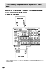
... AUDIO OUT L R A ANTENNA 75Ω COAXIAL FM DIGITAL CD/SACD OPTICAL IN U IR REMOTE MONITOR TV/SAT DVD/LD VIDEO 2 IN STATUS IN ... IN IN OUT IN Y VIDEO 1 OUT S2 VIDEO OUT IN CTRL A1 MD/DAT OPTICAL OUT MD/DAT OPTICAL IN TV/SAT OPTICAL IN DVD/LD OPTICAL IN CD/SACD COAXIAL IN DVD/LD COAXIAL IN ASSIGNABLE IR OUT 1 IR OUT 2... R RS232C SUB WOOFER MULTI CHANNEL IN 2 SUB WOOFER MULTI CHANNEL IN 1 PRE OUT SUB WOOFER VARIABLE 3RD ROOM E* OUTPUT DIGITAL OPTICAL F* OUTPUT DIGITAL COAXIAL A OUTPUT AUDIO OUT L R DVD/LD player * Connect to the COAXIAL IN jack. 10GB 1a: Connecting...
... AUDIO OUT L R A ANTENNA 75Ω COAXIAL FM DIGITAL CD/SACD OPTICAL IN U IR REMOTE MONITOR TV/SAT DVD/LD VIDEO 2 IN STATUS IN ... IN IN OUT IN Y VIDEO 1 OUT S2 VIDEO OUT IN CTRL A1 MD/DAT OPTICAL OUT MD/DAT OPTICAL IN TV/SAT OPTICAL IN DVD/LD OPTICAL IN CD/SACD COAXIAL IN DVD/LD COAXIAL IN ASSIGNABLE IR OUT 1 IR OUT 2... R RS232C SUB WOOFER MULTI CHANNEL IN 2 SUB WOOFER MULTI CHANNEL IN 1 PRE OUT SUB WOOFER VARIABLE 3RD ROOM E* OUTPUT DIGITAL OPTICAL F* OUTPUT DIGITAL COAXIAL A OUTPUT AUDIO OUT L R DVD/LD player * Connect to the COAXIAL IN jack. 10GB 1a: Connecting...
Operating Instructions
Page 11
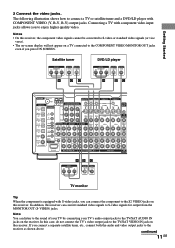
... R-Y B-Y Y OUTPUT VIDEO OUTPUT S VIDEO DVD/LD player OUTPUT COMPONENT R-Y B-Y Y OUTPUT S VIDEO OUTPUT VIDEO H CD H DC ANTENNA 75Ω COAXIAL FM DIGITAL CD/SACD OPTICAL IN U IR REMOTE MONITOR TV/SAT DVD/LD VIDEO 2 IN STATUS IN OUT COMPONENT VIDEO CONTROL S AM TV/SAT IN DVD/LD IN MONITOR OUT...VIDEO TV monitor Tip When the component is equipped with S-video jacks, you can connect the component to the S2 VIDEO jacks on this receiver, the component video signals cannot be converted to S-video or standard video signals (or vice versa). • The on-screen display will...
... R-Y B-Y Y OUTPUT VIDEO OUTPUT S VIDEO DVD/LD player OUTPUT COMPONENT R-Y B-Y Y OUTPUT S VIDEO OUTPUT VIDEO H CD H DC ANTENNA 75Ω COAXIAL FM DIGITAL CD/SACD OPTICAL IN U IR REMOTE MONITOR TV/SAT DVD/LD VIDEO 2 IN STATUS IN OUT COMPONENT VIDEO CONTROL S AM TV/SAT IN DVD/LD IN MONITOR OUT...VIDEO TV monitor Tip When the component is equipped with S-video jacks, you can connect the component to the S2 VIDEO jacks on this receiver, the component video signals cannot be converted to S-video or standard video signals (or vice versa). • The on-screen display will...

Operating Instructions
Page 12
... CD player OUTPUT AUDIO OUT L R OUTPUT DIGITAL COAXIAL OUTPUT DIGITAL OPTICAL A F* E* MD/DAT deck DIGITAL OPTICAL IN OUT INPUT OUTPUT LINE LINE L R E OUT E A IN OUT A IN ç ç ç ç ANTENNA 75Ω COAXIAL FM DIGITAL CD/SACD OPTICAL IN U IR REMOTE MONITOR TV/SAT DVD/LD VIDEO 2 IN ...the RF demodulator. Notes • No sound is output when playing a Super Audio CD disc on a Super Audio CD player connected to this receiver. Tips • All the digital audio jacks are compatible with 32 kHz, 44.1 kHz, 48 kHz and 96 kHz sampling frequencies. •...
... CD player OUTPUT AUDIO OUT L R OUTPUT DIGITAL COAXIAL OUTPUT DIGITAL OPTICAL A F* E* MD/DAT deck DIGITAL OPTICAL IN OUT INPUT OUTPUT LINE LINE L R E OUT E A IN OUT A IN ç ç ç ç ANTENNA 75Ω COAXIAL FM DIGITAL CD/SACD OPTICAL IN U IR REMOTE MONITOR TV/SAT DVD/LD VIDEO 2 IN ...the RF demodulator. Notes • No sound is output when playing a Super Audio CD disc on a Super Audio CD player connected to this receiver. Tips • All the digital audio jacks are compatible with 32 kHz, 44.1 kHz, 48 kHz and 96 kHz sampling frequencies. •...

Operating Instructions
Page 13
...and CD/Super Audio CD players are equipped with multi channel output jacks 1 Connect the audio jacks. continued 13GB ANTENNA 75Ω COAXIAL FM DIGITAL CD/SACD OPTICAL IN U IR REMOTE MONITOR TV/SAT DVD/LD VIDEO 2 IN STATUS IN OUT COMPONENT VIDEO CONTROL S AM TV/SAT IN DVD/... Note DVD and Super Audio CD players do not have SURR BACK terminals. Alternatively, the multi channel input jacks can connect them to this receiver's MULTI CHANNEL IN jacks to enjoy the sound of the component. Getting Started 1b: Connecting components with multi channel decoder, you to enjoy software...
...and CD/Super Audio CD players are equipped with multi channel output jacks 1 Connect the audio jacks. continued 13GB ANTENNA 75Ω COAXIAL FM DIGITAL CD/SACD OPTICAL IN U IR REMOTE MONITOR TV/SAT DVD/LD VIDEO 2 IN STATUS IN OUT COMPONENT VIDEO CONTROL S AM TV/SAT IN DVD/... Note DVD and Super Audio CD players do not have SURR BACK terminals. Alternatively, the multi channel input jacks can connect them to this receiver's MULTI CHANNEL IN jacks to enjoy the sound of the component. Getting Started 1b: Connecting components with multi channel decoder, you to enjoy software...

Operating Instructions
Page 14
... VIDEO (Y, B-Y, R-Y) output jacks. Connecting a TV with component video input jacks allows you press ON SCREEN. Notes • On this receiver, the component video signals cannot be converted to S-video or standard video signals (or vice versa). • The on-screen display will ... TV connected to the S2 VIDEO jacks on the receiver. DVD/LD player OUTPUT S VIDEO OUTPUT VIDEO OUTPUT COMPONENT R-Y B-Y Y DC H TV monitor INPUT COMPONENT R-Y B-Y Y INPUT S VIDEO INPUT VIDEO H DC ANTENNA 75Ω COAXIAL FM DIGITAL CD/SACD OPTICAL IN U IR REMOTE MONITOR TV/SAT DVD/LD...
... VIDEO (Y, B-Y, R-Y) output jacks. Connecting a TV with component video input jacks allows you press ON SCREEN. Notes • On this receiver, the component video signals cannot be converted to S-video or standard video signals (or vice versa). • The on-screen display will ... TV connected to the S2 VIDEO jacks on the receiver. DVD/LD player OUTPUT S VIDEO OUTPUT VIDEO OUTPUT COMPONENT R-Y B-Y Y DC H TV monitor INPUT COMPONENT R-Y B-Y Y INPUT S VIDEO INPUT VIDEO H DC ANTENNA 75Ω COAXIAL FM DIGITAL CD/SACD OPTICAL IN U IR REMOTE MONITOR TV/SAT DVD/LD...

Operating Instructions
Page 15
continued 15GB MD/DAT deck Turntable INPUT OUTPUT LINE LINE L R A A OUT A IN ç ç ANTENNA 75Ω COAXIAL FM DIGITAL CD/SACD OPTICAL IN U IR REMOTE MONITOR TV/SAT DVD/LD VIDEO 2 IN STATUS IN OUT COMPONENT VIDEO CONTROL S AM TV/SAT IN DVD/LD IN MONITOR OUT ... S2 VIDEO S2 VIDEO S2 VIDEO OUT IN IN OUT IN Y VIDEO 1 OUT S2 VIDEO OUT IN CTRL A1 MD/DAT OPTICAL OUT MD/DAT OPTICAL IN TV/SAT OPTICAL IN DVD/LD OPTICAL IN CD/SACD COAXIAL IN DVD/LD COAXIAL IN ASSIGNABLE IR OUT 1 IR OUT 2 PB/CB/B-Y PR/CR/R-Y VIDEO OUT...
continued 15GB MD/DAT deck Turntable INPUT OUTPUT LINE LINE L R A A OUT A IN ç ç ANTENNA 75Ω COAXIAL FM DIGITAL CD/SACD OPTICAL IN U IR REMOTE MONITOR TV/SAT DVD/LD VIDEO 2 IN STATUS IN OUT COMPONENT VIDEO CONTROL S AM TV/SAT IN DVD/LD IN MONITOR OUT ... S2 VIDEO S2 VIDEO S2 VIDEO OUT IN IN OUT IN Y VIDEO 1 OUT S2 VIDEO OUT IN CTRL A1 MD/DAT OPTICAL OUT MD/DAT OPTICAL IN TV/SAT OPTICAL IN DVD/LD OPTICAL IN CD/SACD COAXIAL IN DVD/LD COAXIAL IN ASSIGNABLE IR OUT 1 IR OUT 2 PB/CB/B-Y PR/CR/R-Y VIDEO OUT...
Operating Instructions
Page 16
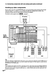
... SCREEN. If you connect a separate satellite tuner, etc., connect both the audio and video output jacks to the TV/SAT VIDEO IN jack on the receiver. In addition, you can connect the component to the S2 VIDEO jacks on this case, do not connect the TV's video output jack to the...'s audio output jacks to the TV/SAT AUDIO IN jacks on the receiver. For details on the required cords (A-H), see page 9. TV monitor INPUT VIDEO INPUT S VIDEO CD To the VIDEO 3 INPUT jacks ANTENNA 75Ω COAXIAL FM DIGITAL CD/SACD OPTICAL IN U IR REMOTE MONITOR TV/SAT DVD/LD VIDEO 2 IN STATUS...
... SCREEN. If you connect a separate satellite tuner, etc., connect both the audio and video output jacks to the TV/SAT VIDEO IN jack on the receiver. In addition, you can connect the component to the S2 VIDEO jacks on this case, do not connect the TV's video output jack to the...'s audio output jacks to the TV/SAT AUDIO IN jacks on the receiver. For details on the required cords (A-H), see page 9. TV monitor INPUT VIDEO INPUT S VIDEO CD To the VIDEO 3 INPUT jacks ANTENNA 75Ω COAXIAL FM DIGITAL CD/SACD OPTICAL IN U IR REMOTE MONITOR TV/SAT DVD/LD VIDEO 2 IN STATUS...
Operating Instructions
Page 17
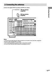
... S2 VIDEO S2 VIDEO S2 VIDEO OUT IN IN OUT IN Y VIDEO 1 OUT S2 VIDEO OUT IN CTRL A1 MD/DAT OPTICAL OUT MD/DAT OPTICAL IN TV/SAT OPTICAL IN DVD/LD OPTICAL IN CD/SACD COAXIAL IN DVD/LD COAXIAL IN ASSIGNABLE IR OUT 1 IR OUT 2 PB/CB/B-Y PR/CR/R-Y VIDEO OUT... VARIABLE 3RD ROOM Notes • To prevent noise pickup, keep the AM loop antenna away from the receiver and other components. • Be sure to fully extend the FM wire antenna. • After connecting the FM wire antenna, keep it as horizontal as possible. • Do not use the U SIGNAL GND terminal for...
... S2 VIDEO S2 VIDEO S2 VIDEO OUT IN IN OUT IN Y VIDEO 1 OUT S2 VIDEO OUT IN CTRL A1 MD/DAT OPTICAL OUT MD/DAT OPTICAL IN TV/SAT OPTICAL IN DVD/LD OPTICAL IN CD/SACD COAXIAL IN DVD/LD COAXIAL IN ASSIGNABLE IR OUT 1 IR OUT 2 PB/CB/B-Y PR/CR/R-Y VIDEO OUT... VARIABLE 3RD ROOM Notes • To prevent noise pickup, keep the AM loop antenna away from the receiver and other components. • Be sure to fully extend the FM wire antenna. • After connecting the FM wire antenna, keep it as horizontal as possible. • Do not use the U SIGNAL GND terminal for...

Operating Instructions
Page 33
.../Tuner Operation 0 MPEG: Lights up when MPEG signals are input. qd COAX: Lights up when the source signal is a digital signal being input through the OPTICAL terminal. Multi channel surround sound is NOT set to indicate the level. When the sound of the input signal the bar indication will fluctuate (and...
.../Tuner Operation 0 MPEG: Lights up when MPEG signals are input. qd COAX: Lights up when the source signal is a digital signal being input through the OPTICAL terminal. Multi channel surround sound is NOT set to indicate the level. When the sound of the input signal the bar indication will fluctuate (and...

Operating Instructions
Page 41
...TAPE t MD/DAT (ANALOG) t CD/SACD (ANALOG) All other analog functions NO ASSIGN t DVD/LD (COAXIAL) t DVD/LD (OPTICAL) t TV/SAT (OPTICAL) t MD/DAT (OPTICAL) t CD/SACD (COAXIAL) t CD/SACD (OPTICAL) Tips • When you can assign varies for which an audio input is assigned, the AUDIO SPLIT button lights up. •...or MULTI CH DIRECT function is convenient in the following cases. (Example) When you do not press AUDIO SPLIT within 8 seconds, the receiver automatically assigns the audio input displayed in step 1. Connect the first DVD player to the DVD/LD COAXIAL IN jack and connect the second...
...TAPE t MD/DAT (ANALOG) t CD/SACD (ANALOG) All other analog functions NO ASSIGN t DVD/LD (COAXIAL) t DVD/LD (OPTICAL) t TV/SAT (OPTICAL) t MD/DAT (OPTICAL) t CD/SACD (COAXIAL) t CD/SACD (OPTICAL) Tips • When you can assign varies for which an audio input is assigned, the AUDIO SPLIT button lights up. •...or MULTI CH DIRECT function is convenient in the following cases. (Example) When you do not press AUDIO SPLIT within 8 seconds, the receiver automatically assigns the audio input displayed in step 1. Connect the first DVD player to the DVD/LD COAXIAL IN jack and connect the second...

Operating Instructions
Page 42
...audio signals. • COAXIAL FIXED Specifies the digital audio signals input to the DIGITAL COAXIAL input jacks. • OPTICAL FIXED Specifies the digital audio signals input to the DIGITAL OPTICAL input jacks. • ANALOG 2CH FIXED Specifies the analog audio signals input to the MULTI CHANNEL IN 1/2 jacks.... have digital audio input jacks. You can switch the audio input mode for digital components (INPUT MODE) You can also select the COAXIAL or OPTICAL audio inputs of "AUTO 2CH" and "ANALOG 2CH FIXED". • AUTO MULTI CH 1/2 Gives priority to the analog audio signals input to...
...audio signals. • COAXIAL FIXED Specifies the digital audio signals input to the DIGITAL COAXIAL input jacks. • OPTICAL FIXED Specifies the digital audio signals input to the DIGITAL OPTICAL input jacks. • ANALOG 2CH FIXED Specifies the analog audio signals input to the MULTI CHANNEL IN 1/2 jacks.... have digital audio input jacks. You can switch the audio input mode for digital components (INPUT MODE) You can also select the COAXIAL or OPTICAL audio inputs of "AUTO 2CH" and "ANALOG 2CH FIXED". • AUTO MULTI CH 1/2 Gives priority to the analog audio signals input to...

Operating Instructions
Page 60
... To resume audio recording from a video tape or laser disc. Recording on a MiniDisc or cassette tape using the receiver. Analog recording is selected. You can record from DIGITAL OUT jacks (MD/DAT OPTICAL OUT) when ANALOG DIRECT is not possible if you may not be recorded. 2 Prepare the component for recording. 4 Start... on a video tape You can also add audio from a variety of the current function are output from a VCR, a TV, or an LD player using the receiver.
... To resume audio recording from a video tape or laser disc. Recording on a MiniDisc or cassette tape using the receiver. Analog recording is selected. You can record from DIGITAL OUT jacks (MD/DAT OPTICAL OUT) when ANALOG DIRECT is not possible if you may not be recorded. 2 Prepare the component for recording. 4 Start... on a video tape You can also add audio from a variety of the current function are output from a VCR, a TV, or an LD player using the receiver.
Operating Instructions
Page 61
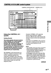
... IN/OUT CONTROL A1 ANTENNA 75Ω COAXIAL FM DIGITAL CD/SACD OPTICAL IN U IR REMOTE MONITOR TV/SAT DVD/LD... VIDEO 2 IN STATUS IN OUT COMPONENT VIDEO CONTROL S AM TV/SAT IN DVD/LD IN MONITOR OUT S2 VIDEO S2 VIDEO S2 VIDEO S2 VIDEO OUT IN IN OUT IN Y VIDEO 1 OUT S2 VIDEO OUT IN CTRL A1 MD/DAT OPTICAL... OUT MD/DAT OPTICAL IN TV/SAT OPTICAL IN DVD/LD OPTICAL IN CD/SACD COAXIAL IN ...Started This section explains the basic functions of separate Sony components. In this may cause the application to handle...
... IN/OUT CONTROL A1 ANTENNA 75Ω COAXIAL FM DIGITAL CD/SACD OPTICAL IN U IR REMOTE MONITOR TV/SAT DVD/LD... VIDEO 2 IN STATUS IN OUT COMPONENT VIDEO CONTROL S AM TV/SAT IN DVD/LD IN MONITOR OUT S2 VIDEO S2 VIDEO S2 VIDEO S2 VIDEO OUT IN IN OUT IN Y VIDEO 1 OUT S2 VIDEO OUT IN CTRL A1 MD/DAT OPTICAL... OUT MD/DAT OPTICAL IN TV/SAT OPTICAL IN DVD/LD OPTICAL IN CD/SACD COAXIAL IN ...Started This section explains the basic functions of separate Sony components. In this may cause the application to handle...
Operating Instructions
Page 67
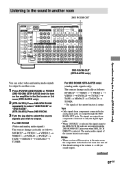
..., the signals input to the analog input jacks are output. Listening to the sound in another room 2ND ROOM OUT ANTENNA 75Ω COAXIAL FM DIGITAL CD/SACD OPTICAL IN U IR REMOTE MONITOR TV/SAT DVD/LD VIDEO 2 IN STATUS IN OUT COMPONENT VIDEO CONTROL S AM TV/SAT IN DVD/LD IN... another room. 1 Press POWER (2ND ROOM) or POWER (3RD ROOM) (STR-DA7ES only) to turn on the amplifier in the 2nd or 3rd room also turn off the receiver in the main room, the components in the 2nd room or 3rd room (STR-DA7ES only). 2 (STR-DA7ES) Press 2ND/3RD ROOM repeatedly to select "2ND ROOM" or...
..., the signals input to the analog input jacks are output. Listening to the sound in another room 2ND ROOM OUT ANTENNA 75Ω COAXIAL FM DIGITAL CD/SACD OPTICAL IN U IR REMOTE MONITOR TV/SAT DVD/LD VIDEO 2 IN STATUS IN OUT COMPONENT VIDEO CONTROL S AM TV/SAT IN DVD/LD IN... another room. 1 Press POWER (2ND ROOM) or POWER (3RD ROOM) (STR-DA7ES only) to turn on the amplifier in the 2nd or 3rd room also turn off the receiver in the main room, the components in the 2nd room or 3rd room (STR-DA7ES only). 2 (STR-DA7ES) Press 2ND/3RD ROOM repeatedly to select "2ND ROOM" or...
Operating Instructions
Page 76
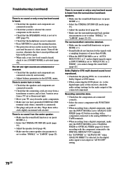
...the INPUT MODE is set to "AUTO MULTI CH 1 or 2" and no digital signal is input, or INPUT MODE is set to COAXIAL FIXED or OPTICAL FIXED (page 42) before recording with a component connected to the analog MD/DAT or TAPE terminals. • When recording from the audio components. ... • Make sure the center speaker size parameter is set to either "SMALL" or "LARGE" (page 22). to the digital input jacks of this receiver, check the audio setting (settings for the signals with a sampling frequency of the connected component. Troubleshooting (continued) There is no sound or only a very...
...the INPUT MODE is set to "AUTO MULTI CH 1 or 2" and no digital signal is input, or INPUT MODE is set to COAXIAL FIXED or OPTICAL FIXED (page 42) before recording with a component connected to the analog MD/DAT or TAPE terminals. • When recording from the audio components. ... • Make sure the center speaker size parameter is set to either "SMALL" or "LARGE" (page 22). to the digital input jacks of this receiver, check the audio setting (settings for the signals with a sampling frequency of the connected component. Troubleshooting (continued) There is no sound or only a very...


