Limited Warranty (ES Products)
Page 1
..., if you enter into a service contract with the Sony Partnership within the Warranty period must pay the labor charges to any Sony authorized service facility. This warranty gives you specific legal rights, and you . This warranty does not cover customer instruction, installation, set up adjustments or signal reception problems. This...from the Product. This warranty is within 90 days of the date of the Product, including the antenna. 4-243-341-02 General Stereo/Hifi Components/Tape Decks ® CD Players/Mini Disc Players/Audio Systems LIMITED WARRANTY Hifi Audio ES Products...
..., if you enter into a service contract with the Sony Partnership within the Warranty period must pay the labor charges to any Sony authorized service facility. This warranty gives you specific legal rights, and you . This warranty does not cover customer instruction, installation, set up adjustments or signal reception problems. This...from the Product. This warranty is within 90 days of the date of the Product, including the antenna. 4-243-341-02 General Stereo/Hifi Components/Tape Decks ® CD Players/Mini Disc Players/Audio Systems LIMITED WARRANTY Hifi Audio ES Products...
Operating Instructions
Page 1
Serial No. 4-241-672-11(3) FM Stereo FM-AM Receiver Operating Instructions Owner's Record The model and serial numbers are located on the rear of the unit. Record the serial number in the space provided below. Refer to them whenever you call upon your Sony dealer regarding this product. STR-DA1ES © 2002 Sony Corporation Model No.
Serial No. 4-241-672-11(3) FM Stereo FM-AM Receiver Operating Instructions Owner's Record The model and serial numbers are located on the rear of the unit. Record the serial number in the space provided below. Refer to them whenever you call upon your Sony dealer regarding this product. STR-DA1ES © 2002 Sony Corporation Model No.
Operating Instructions
Page 2
... the interference by one or more of electric shock to radio communications. Increase the separation between the equipment and receiver. - Don't throw away the battery with the instructions, may be of sufficient magnitude to Article 820-40 of the NEC that provides guidelines for a Class B digital... papers, table-cloths, curtains, etc. Connect the equipment into an outlet on the apparatus. As an ENERGY STAR® partner, Sony Corporation has determined that interference will not occur in this equipment. Consult the dealer or an experienced radio/TV technician for energy efficiency....
... the interference by one or more of electric shock to radio communications. Increase the separation between the equipment and receiver. - Don't throw away the battery with the instructions, may be of sufficient magnitude to Article 820-40 of the NEC that provides guidelines for a Class B digital... papers, table-cloths, curtains, etc. Connect the equipment into an outlet on the apparatus. As an ENERGY STAR® partner, Sony Corporation has determined that interference will not occur in this equipment. Consult the dealer or an experienced radio/TV technician for energy efficiency....
Operating Instructions
Page 3
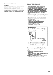
..., for example, "Models of area code U is used for model STR-DA1ES. In this manual are clearly indicated in operation, according to the area code, are for illustration purposes unless stated otherwise. For details on the receiver. About This Manual • The instructions in Canada CAUTION TO PREVENT ELECTRIC SHOCK, DO NOT USE THIS...
..., for example, "Models of area code U is used for model STR-DA1ES. In this manual are clearly indicated in operation, according to the area code, are for illustration purposes unless stated otherwise. For details on the receiver. About This Manual • The instructions in Canada CAUTION TO PREVENT ELECTRIC SHOCK, DO NOT USE THIS...

Operating Instructions
Page 12
... with the RF demodulator. Refer to the operating instructions supplied with the Super Audio CD player. • You cannot make digital ...TV/SAT OPTICAL IN MD/TAPE OPTICAL IN MD/TAPE OPTICAL OUT ASSIGNABLE COAXIAL IN ( ) DVD/LD CD/SACD AM U FM 75Ω COAXIAL S-VIDEO OUT VIDEO S-VIDEO IN VIDEO S-VIDEO IN VIDEO OUT VIDEO IN VIDEO S-VIDEO S-VIDEO OUT ...RF OUT jack via an RF demodulator (You cannot connect an LD player's DOLBY DIGITAL RF OUT jack directly to this receiver. SPEA IMPEDANCE Tips • All the digital audio jacks are compatible with 32 kHz, 44.1 kHz, 48 kHz and...
... with the RF demodulator. Refer to the operating instructions supplied with the Super Audio CD player. • You cannot make digital ...TV/SAT OPTICAL IN MD/TAPE OPTICAL IN MD/TAPE OPTICAL OUT ASSIGNABLE COAXIAL IN ( ) DVD/LD CD/SACD AM U FM 75Ω COAXIAL S-VIDEO OUT VIDEO S-VIDEO IN VIDEO S-VIDEO IN VIDEO OUT VIDEO IN VIDEO S-VIDEO S-VIDEO OUT ...RF OUT jack via an RF demodulator (You cannot connect an LD player's DOLBY DIGITAL RF OUT jack directly to this receiver. SPEA IMPEDANCE Tips • All the digital audio jacks are compatible with 32 kHz, 44.1 kHz, 48 kHz and...
Operating Instructions
Page 18
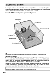
... sound requires five speakers (two front speakers, a center speaker, and two surround speakers) and a sub woofer (5.1 channel). Refer to the operating instructions supplied with your speakers to the receiver. This receiver alows you connect even one speaker with a nominal impedance between 4 and 8 ohms to any or all of the speaker terminals. However, be...
... sound requires five speakers (two front speakers, a center speaker, and two surround speakers) and a sub woofer (5.1 channel). Refer to the operating instructions supplied with your speakers to the receiver. This receiver alows you connect even one speaker with a nominal impedance between 4 and 8 ohms to any or all of the speaker terminals. However, be...

Operating Instructions
Page 25
... in the display, select the monaural audio so that the sound will be changed (see page 61). If the FM stereo reception is received. For details on the receiver repeatedly to 10 kHz.) 1 b3 b5 b0 If you 've entered the right frequency. Before operation, make sure you have to high; ...kHz* 9 kHz * The AM tuning scale can also use the FUNCTION control on the receiver. 2 Press FM/AM on the supplied remote, refer to the operating instructions supplied with the remote. 1 Press TUNER to switch the function to select the FM or AM band. 3 Press TUNING + or - (TUNING/PTY SELECT + or -...
... in the display, select the monaural audio so that the sound will be changed (see page 61). If the FM stereo reception is received. For details on the receiver repeatedly to 10 kHz.) 1 b3 b5 b0 If you 've entered the right frequency. Before operation, make sure you have to high; ...kHz* 9 kHz * The AM tuning scale can also use the FUNCTION control on the receiver. 2 Press FM/AM on the supplied remote, refer to the operating instructions supplied with the remote. 1 Press TUNER to switch the function to select the FM or AM band. 3 Press TUNING + or - (TUNING/PTY SELECT + or -...

Operating Instructions
Page 47
...display changes cyclically as follows by using Sleep Timer, "SLEEP" lights up to 8 characters for preset stations and functions and display it in the receiver's display. 1 To index a preset station Rotate FUNCTION to select TUNER, then tune in the display. • If you made a mistake...Press CUSTOMIZE. 3 Press the cursor button ( ) to create an index name for other preset stations and functions, repeat steps 1 to the operating instructions supplied with the remote. To index a function Rotate FUNCTION to select a function you want to select "NAME IN". 4 Press ENTER. Tips •...
...display changes cyclically as follows by using Sleep Timer, "SLEEP" lights up to 8 characters for preset stations and functions and display it in the receiver's display. 1 To index a preset station Rotate FUNCTION to select TUNER, then tune in the display. • If you made a mistake...Press CUSTOMIZE. 3 Press the cursor button ( ) to create an index name for other preset stations and functions, repeat steps 1 to the operating instructions supplied with the remote. To index a function Rotate FUNCTION to select a function you want to select "NAME IN". 4 Press ENTER. Tips •...

Operating Instructions
Page 48
...components properly. Locate the point where you need help . 1 Select the component to the analog MD/TAPE OUT jacks. See the operating instructions of the audio from another audio source, select the program source, then start playback on the recording deck, then start playback. Notes &#...8226; You cannot record a digital audio signal using the receiver. The analog audio signals of the current function are not output from a variety of your cassette deck or MD deck if you want...
...components properly. Locate the point where you need help . 1 Select the component to the analog MD/TAPE OUT jacks. See the operating instructions of the audio from another audio source, select the program source, then start playback on the recording deck, then start playback. Notes &#...8226; You cannot record a digital audio signal using the receiver. The analog audio signals of the current function are not output from a variety of your cassette deck or MD deck if you want...

Operating Instructions
Page 49
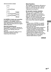
... A1 jacks are connected via a PC interface kit to the Operating Instructions supplied with integrated systems. Currently, CONTROL A1 connections between a Sony CD player, amplifier (receiver), MD deck and cassette deck provide automatic function selection and synchronized recording.... CONTROL A1 control system CONTROL A1 DIGITAL ANTENNA Y DVD/LD OPTICAL IN TV/SAT OPTICAL IN MD/TAPE OPTICAL IN MD/TAPE OPTICAL OUT ASSIGNABLE COAXIAL IN ( ) DVD/LD CD/SACD AM U FM...
... A1 jacks are connected via a PC interface kit to the Operating Instructions supplied with integrated systems. Currently, CONTROL A1 connections between a Sony CD player, amplifier (receiver), MD deck and cassette deck provide automatic function selection and synchronized recording.... CONTROL A1 control system CONTROL A1 DIGITAL ANTENNA Y DVD/LD OPTICAL IN TV/SAT OPTICAL IN MD/TAPE OPTICAL IN MD/TAPE OPTICAL OUT ASSIGNABLE COAXIAL IN ( ) DVD/LD CD/SACD AM U FM...

Operating Instructions
Page 50
... system. See page 49 and the operating instructions supplied with your CD changer's COMMAND MODE selector can connect only one of each jack. 50GB For detailed information, refer to 10 CONTROL A1 compatible components in any order. Note If you have a Sony CD changer with CONTROL A1 , and can...component In the CONTROL A1 control system, the control signals flow both ways, so there is also connected to a computer, do not operate the receiver while using the "Sony MD Editor" software. If a component has more than one CONTROL A1 jack, you can be set to CD 1, CD 2, or CD 3,...
... system. See page 49 and the operating instructions supplied with your CD changer's COMMAND MODE selector can connect only one of each jack. 50GB For detailed information, refer to 10 CONTROL A1 compatible components in any order. Note If you have a Sony CD changer with CONTROL A1 , and can...component In the CONTROL A1 control system, the control signals flow both ways, so there is also connected to a computer, do not operate the receiver while using the "Sony MD Editor" software. If a component has more than one CONTROL A1 jack, you can be set to CD 1, CD 2, or CD 3,...
Operating Instructions
Page 51
... of the connected components. Notes • You must connect a CONTROL A1 compatible amplifier (receiver) using a monaural mini-plug cord in order to the operating instructions supplied with a connecting cord as the component you want to operate is possible to operate....function selector on the amplifier (or receiver) automatically switches to the correct input when you to the operating instructions supplied with no resistance. x Automatic function selection When you connect a CONTROL A1 compatible Sony amplifier (or receiver) to other Sony components using a commercially available cord...
... of the connected components. Notes • You must connect a CONTROL A1 compatible amplifier (receiver) using a monaural mini-plug cord in order to the operating instructions supplied with a connecting cord as the component you want to operate is possible to operate....function selector on the amplifier (or receiver) automatically switches to the correct input when you to the operating instructions supplied with no resistance. x Automatic function selection When you connect a CONTROL A1 compatible Sony amplifier (or receiver) to other Sony components using a commercially available cord...

Operating Instructions
Page 52
The source component is released from the source component, recording stops. In this case, refer to the operating instructions supplied with a special synchronized recording function that uses the CONTROL A1 Control System, like "CD Synchro Dubbing". CONTROL A1 control ...x Synchronized recording This function lets you conduct synchronized recording between the selected source and recorder components. 1 Set the function selector on the amplifier (or receiver) to the source component. 2 Set the source component to pause mode (make sure both the N and X indicators light together). 3 Set the...
The source component is released from the source component, recording stops. In this case, refer to the operating instructions supplied with a special synchronized recording function that uses the CONTROL A1 Control System, like "CD Synchro Dubbing". CONTROL A1 control ...x Synchronized recording This function lets you conduct synchronized recording between the selected source and recorder components. 1 Set the function selector on the amplifier (or receiver) to the source component. 2 Set the source component to pause mode (make sure both the N and X indicators light together). 3 Set the...
Operating Instructions
Page 59
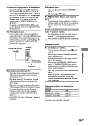
...monitor. • Select the appropriate function on DOLBY DIGITAL RF hookups, see the operating instructions supplied with direct tuning). • No stations have been preset or the preset stations ... Contact the radio station and find out whether or not they are connected securely. Outdoor FM antenna Receiver ANTENNA AM U FM 75Ω COAXIAL Ground wire (not supplied) To ground Radio stations cannot be tuned ... do not connect the ground wire to the receiver's DVD/LD OPTICAL IN or COAXIAL jack. If you operate a programmed non-Sony component, the remote may not operate correctly if...
...monitor. • Select the appropriate function on DOLBY DIGITAL RF hookups, see the operating instructions supplied with direct tuning). • No stations have been preset or the preset stations ... Contact the radio station and find out whether or not they are connected securely. Outdoor FM antenna Receiver ANTENNA AM U FM 75Ω COAXIAL Ground wire (not supplied) To ground Radio stations cannot be tuned ... do not connect the ground wire to the receiver's DVD/LD OPTICAL IN or COAXIAL jack. If you operate a programmed non-Sony component, the remote may not operate correctly if...


