Operating Instructions
Page 2
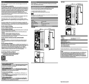
... (3 3/8) Inputs/outputs REMOTE CCU/CNU EXT I/O 8-pin multi-connector, female (1) 9-pin, female (1) Supplied accessories Operation guide (1) Operation manual (CD-ROM) (1) Optional accessories External I/O connector JAE DE-9PF-N 1-568-182-11 CCA-5-3 remote cable (3 m) CCA-5-10 remote cable (10 m) CCA-5-30 remote cable (30 m) Design and specifications are designed to Subpart B of part 15 of the European Community. Please visit http://www.sonybiz.ca/solutions/ Support.do for important information and complete terms and conditions of Sony...
... (3 3/8) Inputs/outputs REMOTE CCU/CNU EXT I/O 8-pin multi-connector, female (1) 9-pin, female (1) Supplied accessories Operation guide (1) Operation manual (CD-ROM) (1) Optional accessories External I/O connector JAE DE-9PF-N 1-568-182-11 CCA-5-3 remote cable (3 m) CCA-5-10 remote cable (10 m) CCA-5-30 remote cable (30 m) Design and specifications are designed to Subpart B of part 15 of the European Community. Please visit http://www.sonybiz.ca/solutions/ Support.do for important information and complete terms and conditions of Sony...
Operation Guide
Page 2
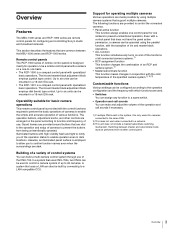
... System Configurations 4 Supported devices 6 Operating Cameras 6 Names and Functions of Parts 7 Operation Panel 7 Connector Panel 12 Settings 13 Setting the Control Panel 13 Adjusting the Brightness of the LED 13 Setting Display Characters to Light-up in malfunction of the Buttons 14 Setting the Call Sound 14 Setting Functions to Assign to the DETAIL Knob ......... 14 Initializing Settings 14 Assigning Functions to the Assignable Button 15 Specifications 15 Note on...
... System Configurations 4 Supported devices 6 Operating Cameras 6 Names and Functions of Parts 7 Operation Panel 7 Connector Panel 12 Settings 13 Setting the Control Panel 13 Adjusting the Brightness of the LED 13 Setting Display Characters to Light-up in malfunction of the Buttons 14 Setting the Call Sound 14 Setting Functions to Assign to the DETAIL Knob ......... 14 Initializing Settings 14 Assigning Functions to the Assignable Button 15 Specifications 15 Note on...
Operation Guide
Page 3
... turns on a one-to-one camera to function and frequency of use of the CNU-700. Switching between the MSU-1000 series and RCP-1000 series. Up to a LAN-compatible CCU. The operation buttons, adjustment knobs, and other controls are dark. Remote control panels The RCP-1000 series of remote control panels is designed mainly for cameras connected to the same CNU. 2) This does not work when connected to a spare switch. • Operation and call sounds...
... turns on a one-to-one camera to function and frequency of use of the CNU-700. Switching between the MSU-1000 series and RCP-1000 series. Up to a LAN-compatible CCU. The operation buttons, adjustment knobs, and other controls are dark. Remote control panels The RCP-1000 series of remote control panels is designed mainly for cameras connected to the same CNU. 2) This does not work when connected to a spare switch. • Operation and call sounds...
Operation Guide
Page 4
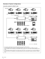
...; Up to 24 systems can be connected if you connect a pair of System Configurations Connection example for LEGACY mode Camera heads CCU CCU (1 to 6) CNU-700 CCU/CNU REMOTE VCS VCS-700 MSU RCP (1 to 6) MSU-1000/1500 RCP-1000/1001 CCA-5 cable • The maximum cable length for cameras connected to 12 systems can be connected if you can connect four MSUs and four VCSs, but...
...; Up to 24 systems can be connected if you connect a pair of System Configurations Connection example for LEGACY mode Camera heads CCU CCU (1 to 6) CNU-700 CCU/CNU REMOTE VCS VCS-700 MSU RCP (1 to 6) MSU-1000/1500 RCP-1000/1001 CCA-5 cable • The maximum cable length for cameras connected to 12 systems can be connected if you can connect four MSUs and four VCSs, but...
Operation Guide
Page 5
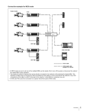
... connected by CCA cable to a RCP connected to turn off the power or disconnect the cable of the master MSU during operation. • The maximum number of the multiple MSUs as the master. A client MSU is counted as one of devices that will be directly connected to the network is 96 excluding the master MSU. Connection example for MCS mode Camera heads CCU RCP-1000 MSU-1000/1500 RCP...
... connected by CCA cable to a RCP connected to turn off the power or disconnect the cable of the master MSU during operation. • The maximum number of the multiple MSUs as the master. A client MSU is counted as one of devices that will be directly connected to the network is 96 excluding the master MSU. Connection example for MCS mode Camera heads CCU RCP-1000 MSU-1000/1500 RCP...
Operation Guide
Page 6
... control panel may not be used to be limited depending on the firmware version. Operating an inactive control panel on which the master camera is to be controlled directly to "Master," and the cameras that are available on the control panel may not function with certain cameras, but this is enabled from an inactive control panel, but this , set the camera that are to display...
... control panel may not be used to be limited depending on the firmware version. Operating an inactive control panel on which the master camera is to be controlled directly to "Master," and the cameras that are available on the control panel may not function with certain cameras, but this is enabled from an inactive control panel, but this , set the camera that are to display...
Operation Guide
Page 7
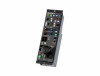
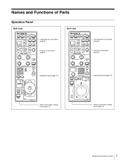
Names and Functions of Parts Operation Panel RCP-1000 RCP-1001 Camera/panel control block (page 8) Function control block (page 9) Camera/panel control block (page 8) Function control block (page 9) Adjustment block (page 10) Adjustment block (page 10) Panel control/status display block (page 12) Panel control/status display block (page 12) 7 Names and Functions of Parts
Names and Functions of Parts Operation Panel RCP-1000 RCP-1001 Camera/panel control block (page 8) Function control block (page 9) Camera/panel control block (page 8) Function control block (page 9) Adjustment block (page 10) Adjustment block (page 10) Panel control/status display block (page 12) Panel control/status display block (page 12) 7 Names and Functions of Parts

Operation Guide
Page 8
... state of that this function is on changes the iris indication to output the corresponding signal. h Camera/CCU function ON/OFF buttons These buttons are only enabled on control panels on for starting auto black balance adjustment. It is not supplied even if the button is for what kind of the lens connected to turn its button is the PARA function button. b CAM PW (camera power) button This button is lit.
... state of that this function is on changes the iris indication to output the corresponding signal. h Camera/CCU function ON/OFF buttons These buttons are only enabled on control panels on for starting auto black balance adjustment. It is not supplied even if the button is for what kind of the lens connected to turn its button is the PARA function button. b CAM PW (camera power) button This button is lit.

Operation Guide
Page 9
... are not lit, the camera side has the control permission. The V button changes them in the opposite direction. When they are not lit, the camera side has the control permission. c CC (color temperature conversion) filter display window This window displays the CC filter that is currently selected. Pressing either the top or bottom button once switches the control permission to the RCP. If there is...
... are not lit, the camera side has the control permission. The V button changes them in the opposite direction. When they are not lit, the camera side has the control permission. c CC (color temperature conversion) filter display window This window displays the CC filter that is currently selected. Pressing either the top or bottom button once switches the control permission to the RCP. If there is...
Operation Guide
Page 10
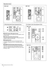
... Functions of Parts b BLACK (manual black balance) knobs These knobs adjust the black balance. For details on assigning functions to assignable buttons, see page 15. c Assignable button This button allows any functions to be adjusted when this button to light. Adjustment block RCP-1000 RCP-1001 1 White balance/black balance adjustment block 2 Iris/master control black adjustment block RCP-1000 a WHITE (manual white balance) knobs These knobs allow you to adjust the R and B signals in order...
... Functions of Parts b BLACK (manual black balance) knobs These knobs adjust the black balance. For details on assigning functions to assignable buttons, see page 15. c Assignable button This button allows any functions to be adjusted when this button to light. Adjustment block RCP-1000 RCP-1001 1 White balance/black balance adjustment block 2 Iris/master control black adjustment block RCP-1000 a WHITE (manual white balance) knobs These knobs allow you to adjust the R and B signals in order...
Operation Guide
Page 11
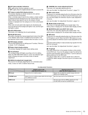
... range from the EXT I/O connector. Sets the upper limit for OPEN, referenced to display the upper and lower limits of manual adjustment. d RELATIVE button This button changes the manual adjustment mode of Parts If the lens is closed, "CLS" is displayed in absolute value mode. Also see the table "Iris Adjustment Functions", (page 11). Press the switch axially to output preview key signals from OPEN to the camera, a black number is displayed in red. b Camera number/tally display window...
... range from the EXT I/O connector. Sets the upper limit for OPEN, referenced to display the upper and lower limits of manual adjustment. d RELATIVE button This button changes the manual adjustment mode of Parts If the lens is closed, "CLS" is displayed in absolute value mode. Also see the table "Iris Adjustment Functions", (page 11). Press the switch axially to output preview key signals from OPEN to the camera, a black number is displayed in red. b Camera number/tally display window...
Operation Guide
Page 12
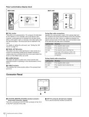
When a call signal is sent (or received), this button and the PARA button are not lit. For details on setting the call sound plays. Alternatively, a connected device is for the control permission. Other Connector Panel a CCU/CNU REMOTE (CCU/CNU remote) connector (8-pin multi-connector, female) This is not recognized. b PANEL ACTIVE button This button is operating on the camera head or CCU/ HDCU. c ALARM indicator This lights red when a system error occurs...
When a call signal is sent (or received), this button and the PARA button are not lit. For details on setting the call sound plays. Alternatively, a connected device is for the control permission. Other Connector Panel a CCU/CNU REMOTE (CCU/CNU remote) connector (8-pin multi-connector, female) This is not recognized. b PANEL ACTIVE button This button is operating on the camera head or CCU/ HDCU. c ALARM indicator This lights red when a system error occurs...
Operation Guide
Page 13
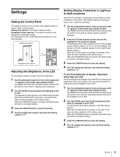
... button will flash and the setting mode will switch to the mode for the character display. The backlight setting value appears in the IRIS display window. When the CLOSE button is pressed, the setting value will reset to its default setting. 3 Press the CAM PW button to save the setting. 4 Turn the setting item selector and reset the setting number to "0". 13 Settings You can adjust operation buttons and LED brightness. 1 Turn the setting item selector in the control...
... button will flash and the setting mode will switch to the mode for the character display. The backlight setting value appears in the IRIS display window. When the CLOSE button is pressed, the setting value will reset to its default setting. 3 Press the CAM PW button to save the setting. 4 Turn the setting item selector and reset the setting number to "0". 13 Settings You can adjust operation buttons and LED brightness. 1 Turn the setting item selector in the control...

Operation Guide
Page 14
... and reset the setting number to "H" for HD Detail or "S" for setting button click volume. 2 Turn the DETAIL knob and adjust the button click volume. The adjustment value appears in the IRIS display window. The call sound volume. When the STANDARD button is pressed, the setting value will switch to "0". The PANEL ACTIVE button will flash and the setting mode will reset to its default setting. 3 Press the CC filter selection button and change the call sound. 1 Turn the setting...
... and reset the setting number to "H" for HD Detail or "S" for setting button click volume. 2 Turn the DETAIL knob and adjust the button click volume. The adjustment value appears in the IRIS display window. The call sound volume. When the STANDARD button is pressed, the setting value will switch to "0". The PANEL ACTIVE button will flash and the setting mode will reset to its default setting. 3 Press the CC filter selection button and change the call sound. 1 Turn the setting...

Operation Guide
Page 15
... ° F to the assignable button. Setting Number Assignable Function 0 NO ASSIGN 1 AUTO KNEE 2 SKIN DETAIL 3 GATE 4 BLACK GAMMA 5 KNEE APERTURE 6 KNEE SAT 7 SATURATION 8 ATW 9 D-EXT A PREVIEW 2 Turn the control panel power back on the control panel. 1 Turn the assignable button selector and set the number of the function to assign to 104 ° F) 1.1 kg (2 lb. 9 oz.) External dimensions RCP-1000 2- 5 (7/32) 68 (2 3/4) Unit: mm (inches) 124 (5) 67...
... ° F to the assignable button. Setting Number Assignable Function 0 NO ASSIGN 1 AUTO KNEE 2 SKIN DETAIL 3 GATE 4 BLACK GAMMA 5 KNEE APERTURE 6 KNEE SAT 7 SATURATION 8 ATW 9 D-EXT A PREVIEW 2 Turn the control panel power back on the control panel. 1 Turn the assignable button selector and set the number of the function to assign to 104 ° F) 1.1 kg (2 lb. 9 oz.) External dimensions RCP-1000 2- 5 (7/32) 68 (2 3/4) Unit: mm (inches) 124 (5) 67...
Operation Guide
Page 16
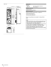
RCP-1001 2- 5 (7/32) 68 (2 3/4) 85 (3 3/8) 67 (2 3/4) 222 (8 3/4) 232.5 (9 1/4) 244 (9 5/8) 68 (2 3/4) Inputs/outputs REMOTE CCU/CNU EXT I/O 8-pin multi-connector, female (1) 9-pin, female (1) Supplied accessories Operation guide (1) Operation manual (CD-ROM) (1) Optional accessories External I/O connector JAE DE-9PF-N 1-568-182-11 CCA-5-3 remote cable (3 m) CCA-5-10 remote cable (10 m) CCA-5-30 remote cable (30 m) Design and specifications are subject to change without notice. Note Always verify that the unit is operating properly before use. SONY WILL NOT BE LIABLE FOR...
RCP-1001 2- 5 (7/32) 68 (2 3/4) 85 (3 3/8) 67 (2 3/4) 222 (8 3/4) 232.5 (9 1/4) 244 (9 5/8) 68 (2 3/4) Inputs/outputs REMOTE CCU/CNU EXT I/O 8-pin multi-connector, female (1) 9-pin, female (1) Supplied accessories Operation guide (1) Operation manual (CD-ROM) (1) Optional accessories External I/O connector JAE DE-9PF-N 1-568-182-11 CCA-5-3 remote cable (3 m) CCA-5-10 remote cable (10 m) CCA-5-30 remote cable (30 m) Design and specifications are subject to change without notice. Note Always verify that the unit is operating properly before use. SONY WILL NOT BE LIABLE FOR...

Operation Guide
Page 17
Sony Corporation expressly prohibits the duplication of any portion of this manual or the use thereof for use by the purchasers of the equipment described in this manual without the express written permission of the equipment described in this manual consists of information that is the property of Sony Corporation and is intended solely for any purpose other than the operation or maintenance of Sony Corporation. The material contained in this manual.
Sony Corporation expressly prohibits the duplication of any portion of this manual or the use thereof for use by the purchasers of the equipment described in this manual without the express written permission of the equipment described in this manual consists of information that is the property of Sony Corporation and is intended solely for any purpose other than the operation or maintenance of Sony Corporation. The material contained in this manual.


