Operation Guide
Page 2
... / Precautions Table of Contents Precautions Precautions 2 Overview 3 Features 3 Examples of System Configurations 4 Supported devices 6 Operating Cameras 6 Names and Functions of Parts 7 Operation Panel 7 Connector Panel 12 Settings 13 Setting the Control Panel 13 Adjusting the Brightness of the LED 13 Setting Display Characters to Light-up in malfunction of the Buttons...
... / Precautions Table of Contents Precautions Precautions 2 Overview 3 Features 3 Examples of System Configurations 4 Supported devices 6 Operating Cameras 6 Names and Functions of Parts 7 Operation Panel 7 Connector Panel 12 Settings 13 Setting the Control Panel 13 Adjusting the Brightness of the LED 13 Setting Display Characters to Light-up in malfunction of the Buttons...
Operation Guide
Page 4
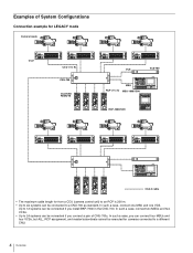
... you can connect four MSUs and four VCSs, but ALL, RCP assignment, and master/subordinate cannot be executed for from a CCU (camera control unit) to an RCP is 200 m. • Up to six systems can be connected to 12 systems can be connected if you install BKP-7930 in the ... a pair of System Configurations Connection example for LEGACY mode Camera heads CCU CCU (1 to 6) CNU-700 CCU/CNU REMOTE VCS VCS-700 MSU RCP (1 to 6) MSU-1000/1500 RCP-1000/1001 CCA-5 cable • The maximum cable length for cameras connected to a different CNU. 4 Overview Up to a CNU-700 as standard.
... you can connect four MSUs and four VCSs, but ALL, RCP assignment, and master/subordinate cannot be executed for from a CCU (camera control unit) to an RCP is 200 m. • Up to six systems can be connected to 12 systems can be connected if you install BKP-7930 in the ... a pair of System Configurations Connection example for LEGACY mode Camera heads CCU CCU (1 to 6) CNU-700 CCU/CNU REMOTE VCS VCS-700 MSU RCP (1 to 6) MSU-1000/1500 RCP-1000/1001 CCA-5 cable • The maximum cable length for cameras connected to a different CNU. 4 Overview Up to a CNU-700 as standard.
Operation Guide
Page 7
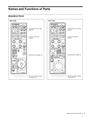
Names and Functions of Parts Operation Panel RCP-1000 RCP-1001 Camera/panel control block (page 8) Function control block (page 9) Camera/panel control block (page 8) Function control block (page 9) Adjustment block (page 10) Adjustment block (page 10) Panel control/status display block (page 12) Panel control/status display block (page 12) 7 Names and Functions of Parts
Names and Functions of Parts Operation Panel RCP-1000 RCP-1001 Camera/panel control block (page 8) Function control block (page 9) Camera/panel control block (page 8) Function control block (page 9) Adjustment block (page 10) Adjustment block (page 10) Panel control/status display block (page 12) Panel control/status display block (page 12) 7 Names and Functions of Parts
Operation Guide
Page 12
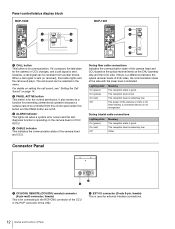
The power of the CNU. Panel control/status display block RCP-1000 RCP-1001 a CALL button This button is off. The call sound can be selected in...state of the camera head and CCU. Alternatively, a connected device is for connecting to the RCP/CNU connector of the CCU or the RCP connector of the camera or CCU is for preventing unintentional operation because a camera cannot be controlled...) This is operating on page 14. If it is pressed, the tally state for external interface connections. 12 Names and Functions of the side with the lower level is extremely low.
The power of the CNU. Panel control/status display block RCP-1000 RCP-1001 a CALL button This button is off. The call sound can be selected in...state of the camera head and CCU. Alternatively, a connected device is for connecting to the RCP/CNU connector of the CCU or the RCP connector of the camera or CCU is for preventing unintentional operation because a camera cannot be controlled...) This is operating on page 14. If it is pressed, the tally state for external interface connections. 12 Names and Functions of the side with the lower level is extremely low.