Operation Guide
Page 2
... panel. Table of Contents Precautions Precautions 2 Overview 3 Features 3 Examples of System Configurations 4 Supported devices 6 Operating Cameras 6 Names and Functions of Parts 7 Operation Panel 7 Connector Panel 12 Settings 13 Setting the Control Panel 13 Adjusting the Brightness of the unit. 2 Precautions / Precautions
... panel. Table of Contents Precautions Precautions 2 Overview 3 Features 3 Examples of System Configurations 4 Supported devices 6 Operating Cameras 6 Names and Functions of Parts 7 Operation Panel 7 Connector Panel 12 Settings 13 Setting the Control Panel 13 Adjusting the Brightness of the unit. 2 Precautions / Precautions
Operation Guide
Page 4
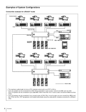
In such a case, you can connect four MSUs and four VCSs, but ALL, RCP assignment, and master/subordinate cannot be executed for from a CCU (camera control unit) to an RCP is 200 m. • Up to six systems can be connected if you connect a pair of System Configurations Connection example for LEGACY... mode Camera heads CCU CCU (1 to 6) CNU-700 CCU/CNU REMOTE VCS VCS-700 MSU RCP (1 to 6) MSU-1000/1500 RCP-1000/1001 CCA-5 cable • The maximum cable length for cameras connected to 12 systems can be connected if you install BKP-7930 in the CNU-700. In such a case, ...
In such a case, you can connect four MSUs and four VCSs, but ALL, RCP assignment, and master/subordinate cannot be executed for from a CCU (camera control unit) to an RCP is 200 m. • Up to six systems can be connected if you connect a pair of System Configurations Connection example for LEGACY... mode Camera heads CCU CCU (1 to 6) CNU-700 CCU/CNU REMOTE VCS VCS-700 MSU RCP (1 to 6) MSU-1000/1500 RCP-1000/1001 CCA-5 cable • The maximum cable length for cameras connected to 12 systems can be connected if you install BKP-7930 in the CNU-700. In such a case, ...
Operation Guide
Page 7
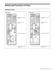
Names and Functions of Parts Operation Panel RCP-1000 RCP-1001 Camera/panel control block (page 8) Function control block (page 9) Camera/panel control block (page 8) Function control block (page 9) Adjustment block (page 10) Adjustment block (page 10) Panel control/status display block (page 12) Panel control/status display block (page 12) 7 Names and Functions of Parts
Names and Functions of Parts Operation Panel RCP-1000 RCP-1001 Camera/panel control block (page 8) Function control block (page 9) Camera/panel control block (page 8) Function control block (page 9) Adjustment block (page 10) Adjustment block (page 10) Panel control/status display block (page 12) Panel control/status display block (page 12) 7 Names and Functions of Parts
Operation Guide
Page 12
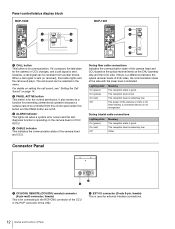
...details on the CHU (camera) side and the CCU side. b PANEL ACTIVE button This button is for connecting to the RCP/CNU connector of the CCU or the RCP connector of the CNU. c ALARM indicator This lights red when a system error occurs and the selfdiagnosis function is low....) This is for the control permission. The reception level is not recognized. Panel control/status display block RCP-1000 RCP-1001 a CALL button This button is for external interface connections. 12 Names and Functions of Parts Likewise, a call signal can be received from this control panel when this ...
...details on the CHU (camera) side and the CCU side. b PANEL ACTIVE button This button is for connecting to the RCP/CNU connector of the CCU or the RCP connector of the CNU. c ALARM indicator This lights red when a system error occurs and the selfdiagnosis function is low....) This is for the control permission. The reception level is not recognized. Panel control/status display block RCP-1000 RCP-1001 a CALL button This button is for external interface connections. 12 Names and Functions of Parts Likewise, a call signal can be received from this control panel when this ...