System Integration Guide
Page 3
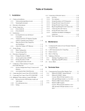
... 1-11-10. Videoconferencing Room Layout 1-1 1-1-2. PCS-G70/G70P 1-5 1-3-2. Inserting Batteries into the Remote Commander 1-9 1-4-2. When the Power is set to 3100 3-1 3-1-3. System Setting 1-17 1-5-1. Dialing Procedure of Software 2-14 2-5-1. Connecting Two Camera Units (PCS-G50/G50P) ....... 1-49 1-10. Relation between...(Custom: When TCP port number is set to 3000 and when UDP port number is set to 3100 3-2 PCS-G70/G70P/G50/G50P 1 Turning On/Off the TV Monitor Together with the Communication Terminal 1-10 1-4-3. Technical Data 3-1. System Setting Table ...
... 1-11-10. Videoconferencing Room Layout 1-1 1-1-2. PCS-G70/G70P 1-5 1-3-2. Inserting Batteries into the Remote Commander 1-9 1-4-2. When the Power is set to 3100 3-1 3-1-3. System Setting 1-17 1-5-1. Dialing Procedure of Software 2-14 2-5-1. Connecting Two Camera Units (PCS-G50/G50P) ....... 1-49 1-10. Relation between...(Custom: When TCP port number is set to 3000 and when UDP port number is set to 3100 3-2 PCS-G70/G70P/G50/G50P 1 Turning On/Off the TV Monitor Together with the Communication Terminal 1-10 1-4-3. Technical Data 3-1. System Setting Table ...

System Integration Guide
Page 4
... 3-2. Displayed Picture at Each Point in Broadcast Mode with Full Screen Mode 3-7 3-5-3. Audio Input/Output Characteristics of PCS-PG70/PG70P/PG50/PG50P 3-4 3-4. Display Transition List of PCS-G70/G70P/G50/G50P 3-6 3-5-1. Displayed Window during Multipoint Connection of PCS-G70/G70P/ G50/G50P 3-11 3-7. Displayed Picture at Each Point in Voice Activate Mode 3-6 3-5-2. Audio Selection List of Communication...
... 3-2. Displayed Picture at Each Point in Broadcast Mode with Full Screen Mode 3-7 3-5-3. Audio Input/Output Characteristics of PCS-PG70/PG70P/PG50/PG50P 3-4 3-4. Display Transition List of PCS-G70/G70P/G50/G50P 3-6 3-5-1. Displayed Window during Multipoint Connection of PCS-G70/G70P/ G50/G50P 3-11 3-7. Displayed Picture at Each Point in Voice Activate Mode 3-6 3-5-2. Audio Selection List of Communication...

System Integration Guide
Page 5
... at maximum zoom-out) 1.5 m (4.92 ft) 100d 4 m (13.12 ft) 65d 100d 5.1 m (16.73 ft) 3.1 m (10.17 ft) 25d 42d 25d 4 m (13.12 ft) PCS-G70/G70P/G50/G50P 1-1 Use the measurements below as a guide for the layout of the camera unit when the zoom has been extended fully. Section 1 Installation 1-1. indicates the...
... at maximum zoom-out) 1.5 m (4.92 ft) 100d 4 m (13.12 ft) 65d 100d 5.1 m (16.73 ft) 3.1 m (10.17 ft) 25d 42d 25d 4 m (13.12 ft) PCS-G70/G70P/G50/G50P 1-1 Use the measurements below as a guide for the layout of the camera unit when the zoom has been extended fully. Section 1 Installation 1-1. indicates the...

System Integration Guide
Page 6
Directional range and layout examples of microphone Extension microphone (PCS-A300 or PCSA-A3) PCS-A300 or PCSA-A3 120d 0.5 to 1 m Camera unit Extension microphone (PCS-A1) PCS-A1 0.5 to 1.2 m Camera unit Microphone layout example using a communication transducer Camera unit CTE-600 1-2 PCS-G70/G70P/G50/G50P
Directional range and layout examples of microphone Extension microphone (PCS-A300 or PCSA-A3) PCS-A300 or PCSA-A3 120d 0.5 to 1 m Camera unit Extension microphone (PCS-A1) PCS-A1 0.5 to 1.2 m Camera unit Microphone layout example using a communication transducer Camera unit CTE-600 1-2 PCS-G70/G70P/G50/G50P

System Integration Guide
Page 7
... more. Choose a room where echo will deteriorate. . Adjust room lighting so that it is used for an in as air conditioners or copy machines. . PCS-G70/G70P/G50/G50P 1-3 Avoid placing the system in a room where there are the speakers used , the sensitivity of the remote commander may decrease the contrast. Layout example...
... more. Choose a room where echo will deteriorate. . Adjust room lighting so that it is used for an in as air conditioners or copy machines. . PCS-G70/G70P/G50/G50P 1-3 Avoid placing the system in a room where there are the speakers used , the sensitivity of the remote commander may decrease the contrast. Layout example...

System Integration Guide
Page 8
End 1-4 PCS-G70/G70P/G50/G50P Initialize the related block. Flowchart of Installation Place used Unpacking Check of supplied accessories Power and cable connection, and preparation Start the power of the system and initialize. 1-2.
End 1-4 PCS-G70/G70P/G50/G50P Initialize the related block. Flowchart of Installation Place used Unpacking Check of supplied accessories Power and cable connection, and preparation Start the power of the system and initialize. 1-2.

System Integration Guide
Page 9
...a wall outlet UTP cable (category 5, straight) ** to LAN TV monitor ** * supplied ** not supplied to audio input to a wall outlet m . PCS-G70/G70P This section describes the typical system connections. Be sure to a network that applies an excess voltage via the 100BASE-TX/10BASE-T connector. 1. Do not...TX/10BASE-T) (with the power on. The AUDIO OUT (MIXED) jack is not used to the MAIN CAMERA connector. . PCS-G70/G70P/G50/G50P 1-5 System Connections 1-3-1. This is used during regular conferences. 1-3. Doing so may damage the camera unit or communication terminal. .
...a wall outlet UTP cable (category 5, straight) ** to LAN TV monitor ** * supplied ** not supplied to audio input to a wall outlet m . PCS-G70/G70P This section describes the typical system connections. Be sure to a network that applies an excess voltage via the 100BASE-TX/10BASE-T connector. 1. Do not...TX/10BASE-T) (with the power on. The AUDIO OUT (MIXED) jack is not used to the MAIN CAMERA connector. . PCS-G70/G70P/G50/G50P 1-5 System Connections 1-3-1. This is used during regular conferences. 1-3. Doing so may damage the camera unit or communication terminal. .

System Integration Guide
Page 10
... not to make an audio recording of a conference. 2. Doing so may cause malfunction of the ISDN unit. This is used during regular conferences. . PCS-B384, PCS-B768 or PCSA-PRI is displayed on . If the system uses only one Monitor) m . The AUDIO OUT (MIXED) jack is not used to ...the power on the monitor screen, be sure to connect it to TERMINAL Interface cable (supplied with an ISDN unit for an ISDN unit. 1-6 PCS-G70/G70P/G50/G50P PCSA-CG70/CG70P Camera unit ISDN unit ** PCSA-B384S ISDN unit ** TERMINAL VISCA OUT to TERMINAL to the MAIN CAMERA connector. .
... not to make an audio recording of a conference. 2. Doing so may cause malfunction of the ISDN unit. This is used during regular conferences. . PCS-B384, PCS-B768 or PCSA-PRI is displayed on . If the system uses only one Monitor) m . The AUDIO OUT (MIXED) jack is not used to ...the power on the monitor screen, be sure to connect it to TERMINAL Interface cable (supplied with an ISDN unit for an ISDN unit. 1-6 PCS-G70/G70P/G50/G50P PCSA-CG70/CG70P Camera unit ISDN unit ** PCSA-B384S ISDN unit ** TERMINAL VISCA OUT to TERMINAL to the MAIN CAMERA connector. .

System Integration Guide
Page 11
PCS-G70/G70P/G50/G50P 1-7 For safety, do not connect the 100BASE-TX/10BASE-T connector to ... the 100BASE-TX/10BASE-T connector. 1. m . 1-3-2. Doing so may damage the camera unit or communication terminal. . PCS-G50/G50P This section describes the typical system connections. Do not connect/disconnect the camera cable with one Camera and one Monitor)... PCSA-CG70/CG70P Camera unit TERMINAL VISCA OUT to TERMINAL PCS-PG50/PG50P Communication terminal Camera cable * to VIDEO IN CAMERA DC 19.5V IR OUT 1 2 AUX CONTROL...
PCS-G70/G70P/G50/G50P 1-7 For safety, do not connect the 100BASE-TX/10BASE-T connector to ... the 100BASE-TX/10BASE-T connector. 1. m . 1-3-2. Doing so may damage the camera unit or communication terminal. . PCS-G50/G50P This section describes the typical system connections. Do not connect/disconnect the camera cable with one Camera and one Monitor)... PCSA-CG70/CG70P Camera unit TERMINAL VISCA OUT to TERMINAL PCS-PG50/PG50P Communication terminal Camera cable * to VIDEO IN CAMERA DC 19.5V IR OUT 1 2 AUX CONTROL...

System Integration Guide
Page 12
...B384S ISDN unit ** TERMINAL VISCA OUT to TERMINAL to TERMINAL Interface cable (supplied with ISDN UNIT) Camera cable * PCS-PG50/PG50P Communication to VIDEO IN terminal CAMERA to ISDN UNIT DC 19.5V IR OUT 1 2 AUX CONTROL CTRL-S... UNIT to ISDN 1-3 PCSA-B768S ISDN unit ** to ISDN 1-6 ISDN modular cable ** to AUDIO OUT to VIDEO OUT MONITOR 1 PCS-AC19V6 AC adaptor Power cord * to DC19.5V to a wall outlet Audio cable * S-video cable * to S-video input TV ... of a conference. While the upgrading message is not used during regular conferences. 1-8 PCS-G70/G70P/G50/G50P
...B384S ISDN unit ** TERMINAL VISCA OUT to TERMINAL to TERMINAL Interface cable (supplied with ISDN UNIT) Camera cable * PCS-PG50/PG50P Communication to VIDEO IN terminal CAMERA to ISDN UNIT DC 19.5V IR OUT 1 2 AUX CONTROL CTRL-S... UNIT to ISDN 1-3 PCSA-B768S ISDN unit ** to ISDN 1-6 ISDN modular cable ** to AUDIO OUT to VIDEO OUT MONITOR 1 PCS-AC19V6 AC adaptor Power cord * to DC19.5V to a wall outlet Audio cable * S-video cable * to S-video input TV ... of a conference. While the upgrading message is not used during regular conferences. 1-8 PCS-G70/G70P/G50/G50P

System Integration Guide
Page 13
... occurs, clean the battery compartment and replace all the batteries with correct polarities into the battery compartment. Remove the battery compartment cover. 2. PCS-RG70 1. Insert two size AAA (R03) batteries (supplied) with new ones. n Be sure to insert the batteries with new ones....new batteries, or different types of time, remove the batteries from possible battery leakage or corrosion, observe the following: . PCSA-RG1 1. PCS-G70/G70P/G50/G50P 3. Make sure to insert the batteries _ side first. Do not attempt to charge the batteries. . 1-4. Attach the cover....
... occurs, clean the battery compartment and replace all the batteries with correct polarities into the battery compartment. Remove the battery compartment cover. 2. PCS-RG70 1. Insert two size AAA (R03) batteries (supplied) with new ones. n Be sure to insert the batteries with new ones....new batteries, or different types of time, remove the batteries from possible battery leakage or corrosion, observe the following: . PCSA-RG1 1. PCS-G70/G70P/G50/G50P 3. Make sure to insert the batteries _ side first. Do not attempt to charge the batteries. . 1-4. Attach the cover....

System Integration Guide
Page 14
The control receiver of a camera unit (PCS-CG70/CG70P). Attach a supplied film to the control receiver surface for improvement when it is difficult to IR...sent m . When an obstacle exists around a camera unit and a remote control signal cannot be sure to standby together with the Communication Terminal If a Sony TV monitor is put in the optimum place using a supplied remote control unit. TERMINAL VISCA OUT MCU VIDEO OUT 1 2 DC 19.5V IR OUT... OUT EC-MIC 1 2 RGB OUT WHITE BOARD 100BASE-TX/ 10BASE-T To CTRL-S DSB ISDN UNIT 1-10 Remote sensor PCS-G70/G70P/G50/G50P
The control receiver of a camera unit (PCS-CG70/CG70P). Attach a supplied film to the control receiver surface for improvement when it is difficult to IR...sent m . When an obstacle exists around a camera unit and a remote control signal cannot be sure to standby together with the Communication Terminal If a Sony TV monitor is put in the optimum place using a supplied remote control unit. TERMINAL VISCA OUT MCU VIDEO OUT 1 2 DC 19.5V IR OUT... OUT EC-MIC 1 2 RGB OUT WHITE BOARD 100BASE-TX/ 10BASE-T To CTRL-S DSB ISDN UNIT 1-10 Remote sensor PCS-G70/G70P/G50/G50P

System Integration Guide
Page 15
... 1. Use the or button on , the camera unit moves automatically for the First Time - m . A Sony TV monitor may not resume moving , it on simultaneously when the communication terminal is installed in the General Setup menu. PCS-G70/G70P/G50/G50P 1-11 1-4-3. The TV monitor will turn on again. . The communication terminal turns on position...
... 1. Use the or button on , the camera unit moves automatically for the First Time - m . A Sony TV monitor may not resume moving , it on simultaneously when the communication terminal is installed in the General Setup menu. PCS-G70/G70P/G50/G50P 1-11 1-4-3. The TV monitor will turn on again. . The communication terminal turns on position...

System Integration Guide
Page 16
...: Selects the output connector to which the device to the RGB OUT connector on the remote commander, then press the PUSH ENTER button. 1-12 PCS-G70/G70P/G50/G50P RGB OUT (DSB): Selects the device connected to be displayed. ISDN Setup Wizard Country/Region Protocol National ISDN Previous Next Cancel Previous Next Cancel...
...: Selects the output connector to which the device to the RGB OUT connector on the remote commander, then press the PUSH ENTER button. 1-12 PCS-G70/G70P/G50/G50P RGB OUT (DSB): Selects the device connected to be displayed. ISDN Setup Wizard Country/Region Protocol National ISDN Previous Next Cancel Previous Next Cancel...

System Integration Guide
Page 17
... Ch5 Ch6 Previous Local Number Next Cancel 9. Select "Next" using the , , , or button on the remote commander, then press the PUSH ENTER button. *: PCS-G70/G70P only PCS-G70/G70P/G50/G50P 1-13 When the ISDN unit PCSA-B768S is used , enter the same number in the text boxes B1 to be used . 10. Enter...-B384S is used to connect two to six ISDN lines, enter sub-addresses in the text boxes B1 to be used . When the ISDN unit PCS-B384/B768 or PCSAB384S/B768S is used , Ch1 to Ch23 (T1), or Ch1 to C2. . To open the menu with the text boxes D1 to...
... Ch5 Ch6 Previous Local Number Next Cancel 9. Select "Next" using the , , , or button on the remote commander, then press the PUSH ENTER button. *: PCS-G70/G70P only PCS-G70/G70P/G50/G50P 1-13 When the ISDN unit PCSA-B768S is used , enter the same number in the text boxes B1 to be used . 10. Enter...-B384S is used to connect two to six ISDN lines, enter sub-addresses in the text boxes B1 to be used . When the ISDN unit PCS-B384/B768 or PCSAB384S/B768S is used , Ch1 to Ch23 (T1), or Ch1 to C2. . To open the menu with the text boxes D1 to...

System Integration Guide
Page 18
... DNS Address Previous Next Cancel DHCP Mode: Sets DHCP (Dynamic Host Configuration Protocol). Host Name: Enter a host name. A confirmation message is recovered, consult a Sony dealer. 1-14 PCS-G70/G70P/G50/G50P OFF: Deactivates DHCP. m . m . If you do not know how to the communication terminal is not re-established even after the system power is...
... DNS Address Previous Next Cancel DHCP Mode: Sets DHCP (Dynamic Host Configuration Protocol). Host Name: Enter a host name. A confirmation message is recovered, consult a Sony dealer. 1-14 PCS-G70/G70P/G50/G50P OFF: Deactivates DHCP. m . m . If you do not know how to the communication terminal is not re-established even after the system power is...

System Integration Guide
Page 19
... not enter the standby mode, set "Standby Mode" in orange. If the IR repeater is installed under the remote sensor of a SONY TV monitor, the TV monitor will go into standby together with the communication terminal. Standby Mode Function To save power, the communication terminal...button on the camera unit goes out. POWER indicator (Not lit.) button POWER indicator (Lights orange.) buttons and PUSH ENTER button PCS-G70/G70P/G50/G50P The video communication system enters standby mode and the POWER indicator on the communication terminal lights in the General Setup menu to ...
... not enter the standby mode, set "Standby Mode" in orange. If the IR repeater is installed under the remote sensor of a SONY TV monitor, the TV monitor will go into standby together with the communication terminal. Standby Mode Function To save power, the communication terminal...button on the camera unit goes out. POWER indicator (Not lit.) button POWER indicator (Lights orange.) buttons and PUSH ENTER button PCS-G70/G70P/G50/G50P The video communication system enters standby mode and the POWER indicator on the communication terminal lights in the General Setup menu to ...

System Integration Guide
Page 20
1-4-4. Adjust the Volume of the communication terminal not to function properly and make strange sounds. 1-16 PCS-G70/G70P/G50/G50P Do not activate the TV's surround sound feature as it may cause the echo canceller of TV Monitor Before adjusting the volume on the ...
1-4-4. Adjust the Volume of the communication terminal not to function properly and make strange sounds. 1-16 PCS-G70/G70P/G50/G50P Do not activate the TV's surround sound feature as it may cause the echo canceller of TV Monitor Before adjusting the volume on the ...

System Integration Guide
Page 21
Still Image menu Camera menu Memory Stick menu Setup menu Still Image menu Camera menu Memory Stick menu Setup menu (for Administrator) PCS-G70/G70P/G50/G50P 1-17 System Setting 1-5-1. Menu Configuration Launcher menu Phone Book/Private Phone Book Detail Dial History Setup Menu Information Selecting the icons shown on the left side of the launcher menu displays each menu. Icon Displayed menu Returns to the previous menu. 1-5.
Still Image menu Camera menu Memory Stick menu Setup menu Still Image menu Camera menu Memory Stick menu Setup menu (for Administrator) PCS-G70/G70P/G50/G50P 1-17 System Setting 1-5-1. Menu Configuration Launcher menu Phone Book/Private Phone Book Detail Dial History Setup Menu Information Selecting the icons shown on the left side of the launcher menu displays each menu. Icon Displayed menu Returns to the previous menu. 1-5.
System Integration Guide
Page 22
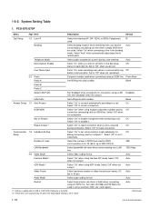
PCS-G70/G70P Menu Page Item Description Default Dial Setup 1/2 Line I/F Select line interface [IP, SIP, ISDN, or ISDN (Telephone)] IP used . Set to a call. Blank Answer ..." when using prefix for multipoint *1. Select "On" to remote party. Auto Restrict Select transmission rate (Auto or 56K) when connecting using them. Auto (Continued) 1-18 PCS-G70/G70P/G50/G50P Select "Auto" when automatically adjusting a line to reject connection when a call . Set to make connection. System Setting Table 1. Blank Prefix-B Prefix-C Select LAN...
PCS-G70/G70P Menu Page Item Description Default Dial Setup 1/2 Line I/F Select line interface [IP, SIP, ISDN, or ISDN (Telephone)] IP used . Set to a call. Blank Answer ..." when using prefix for multipoint *1. Select "On" to remote party. Auto Restrict Select transmission rate (Auto or 56K) when connecting using them. Auto (Continued) 1-18 PCS-G70/G70P/G50/G50P Select "Auto" when automatically adjusting a line to reject connection when a call . Set to make connection. System Setting Table 1. Blank Prefix-B Prefix-C Select LAN...


