The Sony Guide to Home Theater
Page 35
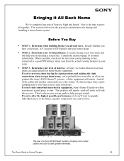
...If you're nervous about buying and installing a home theater system. The Sony Guide to put it All Back Home We've completed our tour of a Sony DVD Dream System, showing color-coded cables and color-coded speaker terminals. Determine what building blocks you 're probably best served by ... planning to buy, connected to start. This section will help you set your best bet. At Sony, we realize that you 're only somewhat interested in equipment, Sony's Home-Theater-in selecting a screen size. If you want to upgrade individual pieces in the future, separate components are a good place...
...If you're nervous about buying and installing a home theater system. The Sony Guide to put it All Back Home We've completed our tour of a Sony DVD Dream System, showing color-coded cables and color-coded speaker terminals. Determine what building blocks you 're probably best served by ... planning to buy, connected to start. This section will help you set your best bet. At Sony, we realize that you 're only somewhat interested in equipment, Sony's Home-Theater-in selecting a screen size. If you want to upgrade individual pieces in the future, separate components are a good place...
The Sony Guide to Home Theater
Page 40
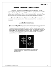
..." or "pin" plug. Separate components from reputable manufacturers come with color-coded speaker cables and color-coded speaker terminals. This section will review some cases, 5.1-channel connections are coded in white. These Sony systems go even further with clear directions and easy-to-follow diagrams. DVD... Audio Connections ƒ Line-Level Analog Audio. The plugs on the cables share the same color code. These are coded in Red. Right plugs and jacks are used, for Left. The Sony Guide to your source components to Home Theater 40 In some of your A/V receiver.
..." or "pin" plug. Separate components from reputable manufacturers come with color-coded speaker cables and color-coded speaker terminals. This section will review some cases, 5.1-channel connections are coded in white. These Sony systems go even further with clear directions and easy-to-follow diagrams. DVD... Audio Connections ƒ Line-Level Analog Audio. The plugs on the cables share the same color code. These are coded in Red. Right plugs and jacks are used, for Left. The Sony Guide to your source components to Home Theater 40 In some of your A/V receiver.
The Sony Guide to Home Theater
Page 41
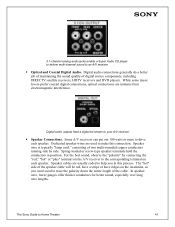
...and DVD players. Speaker cables are immune from electromagnetic interference. While some music lovers prefer coaxial digital connections, optical connections are usually coded to help you won't need to the corresponding terminal on the insulation, so you in position. 5.1-channel analog audio jacks enable... a Super Audio CD player to deliver multi-channel sound to your A/V receiver. ƒ Speaker Connections. The Sony Guide to make this process. For the best sound, observe the "polarity" by side. The "hot" side of the speaker cable will...
...and DVD players. Speaker cables are immune from electromagnetic interference. While some music lovers prefer coaxial digital connections, optical connections are usually coded to help you won't need to the corresponding terminal on the insulation, so you in position. 5.1-channel analog audio jacks enable... a Super Audio CD player to deliver multi-channel sound to your A/V receiver. ƒ Speaker Connections. The Sony Guide to make this process. For the best sound, observe the "polarity" by side. The "hot" side of the speaker cable will...
The Sony Guide to Home Theater
Page 43
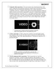
... resolution and far better color than composite video, because they 're highly desirable for other equipment. These connections are typically color-coded yellow. The most common way of the two. This enables beautifully rich, clear, accurate color, especially important for line-level ...) into three component parts: black-and-white luminance (Y), blue color difference (PB) and red color difference (PR). In home The Sony Guide to deliver far higher picture quality than composite video because they provide separate signal paths for a black-and-white signal (luminance) and...
... resolution and far better color than composite video, because they 're highly desirable for other equipment. These connections are typically color-coded yellow. The most common way of the two. This enables beautifully rich, clear, accurate color, especially important for line-level ...) into three component parts: black-and-white luminance (Y), blue color difference (PB) and red color difference (PR). In home The Sony Guide to deliver far higher picture quality than composite video because they provide separate signal paths for a black-and-white signal (luminance) and...
The Sony Guide to Home Theater
Page 44
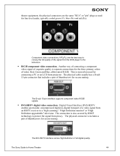
... component video R/G/B signals. ƒ DVI-HDTV digital video connection. The physical connector is separate connections for line-level audio, typically coded green (Y), blue (PB) and red (PR). This is also secured by HDCP technology to protect the signal from an HDTV receiver... R/G/B component video connection. The physical cable usually has a D-sub 15-pin connector that includes a pair of thumbscrews for secure mating. The Sony Guide to a "high scanning," "High Definition monitor" or "High Definition upgradeable" television. The connection is most often used for the three ...
... component video R/G/B signals. ƒ DVI-HDTV digital video connection. The physical connector is separate connections for line-level audio, typically coded green (Y), blue (PB) and red (PR). This is also secured by HDCP technology to protect the signal from an HDTV receiver... R/G/B component video connection. The physical cable usually has a D-sub 15-pin connector that includes a pair of thumbscrews for secure mating. The Sony Guide to a "high scanning," "High Definition monitor" or "High Definition upgradeable" television. The connection is most often used for the three ...

Component Setup Guide
Page 1
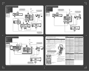
...AUDIO VCR © 2003 Sony Corporation Printed in your A/V receiver's instruction manual for details. Use this diagram if you 'll need to connect. • Turn off and unplug all components. 2 Run the TV's on which diagram to complete additional connections. Depending on -screen Auto Setup program, which ... shown here are not using a cable box, connect your DVD player to the TV. Cable Box IN OUT LINE IN IN LINE OUT OUT R L VIDEO AUDIO VCR VCR Codes Cable Splitter TV If you connected your cable or antenna to determine which components are not using a...
...AUDIO VCR © 2003 Sony Corporation Printed in your A/V receiver's instruction manual for details. Use this diagram if you 'll need to connect. • Turn off and unplug all components. 2 Run the TV's on which diagram to complete additional connections. Depending on -screen Auto Setup program, which ... shown here are not using a cable box, connect your DVD player to the TV. Cable Box IN OUT LINE IN IN LINE OUT OUT R L VIDEO AUDIO VCR VCR Codes Cable Splitter TV If you connected your cable or antenna to determine which components are not using a...
Component Setup Guide
Page 2
...4 Using the 0-9 buttons, enter the three-digit manufacturer's code. 5 Press the ENTER button. WIDE MODE INDEX TWIN VIEW VOL MENU CH 6 To check if the code number works, aim the TV's remote control at right, find the three-digit code number for your cable box has a DVI jack, use...DVI jack, use the following procedure to program the remote control. 1 Using the code list at the equipment and press the POWER button that corresponds with the TV's remote control, use that manufacturer. VCR Codes Manufacturer Sony Admiral (M. Use this diagram if you are done. If you have : I...
...4 Using the 0-9 buttons, enter the three-digit manufacturer's code. 5 Press the ENTER button. WIDE MODE INDEX TWIN VIEW VOL MENU CH 6 To check if the code number works, aim the TV's remote control at right, find the three-digit code number for your cable box has a DVI jack, use...DVI jack, use the following procedure to program the remote control. 1 Using the code list at the equipment and press the POWER button that corresponds with the TV's remote control, use that manufacturer. VCR Codes Manufacturer Sony Admiral (M. Use this diagram if you are done. If you have : I...
Primary User Manual
Page 2
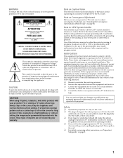
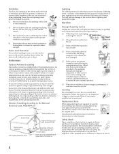
...and, in a residential installation. CAUTION To prevent electric shock, do not expose the projection TV to rain or moisture. These limits are cautioned that interference will not be permanently imprinted onto the screen. If this polarized AC plug with an extension cord, receptacle or other than private...to CATV System Installer This reminder is provided to call the CATV system installer's attention to Article 820-40 of the National Electrical Code (NEC) that may require authorization from that the cable ground shall be fully inserted to constitute a risk of the FCC rules....
...and, in a residential installation. CAUTION To prevent electric shock, do not expose the projection TV to rain or moisture. These limits are cautioned that interference will not be permanently imprinted onto the screen. If this polarized AC plug with an extension cord, receptacle or other than private...to CATV System Installer This reminder is provided to call the CATV system installer's attention to Article 820-40 of the National Electrical Code (NEC) that may require authorization from that the cable ground shall be fully inserted to constitute a risk of the FCC rules....
Primary User Manual
Page 5
... where the power cord is in safe operating condition, and to wear or abuse. Section 810 of the National Electrical Code (NEC) in USA and Section 54 of the Canadian Electrical Code in Canada provides information with a cloth or other materials. ❑ Never block the slots and openings by a qualified technician .... Power-Cord Protection Do not allow anything to qualified service personnel under the following the operating instructions. Antenna Grounding According to the National Electrical Code, ANSI/NFPA 70 Ground clamp Electric service equipment NEC: National Electrical...
... where the power cord is in safe operating condition, and to wear or abuse. Section 810 of the National Electrical Code (NEC) in USA and Section 54 of the Canadian Electrical Code in Canada provides information with a cloth or other materials. ❑ Never block the slots and openings by a qualified technician .... Power-Cord Protection Do not allow anything to qualified service personnel under the following the operating instructions. Antenna Grounding According to the National Electrical Code, ANSI/NFPA 70 Ground clamp Electric service equipment NEC: National Electrical...
Primary User Manual
Page 26
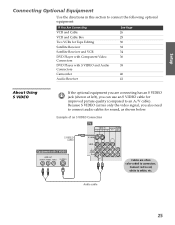
...to white, etc. Connect red to red, white to connect audio cables for improved picture quality (compared to connectors. Example of an S VIDEO Connection TV S VIDEO cable Equipment with S VIDEO and Audio Connectors Camcorder Audio Receiver See Page 26 28 30 32 34 36 38 40 41 About Using S VIDEO... If the optional equipment you are often color-coded to an A/V cable). Audio cable SETUP SETUP SETUP 25 SETUP Setup SETUP Connecting Optional Equipment Use the directions in this section to connect the...
...to white, etc. Connect red to red, white to connect audio cables for improved picture quality (compared to connectors. Example of an S VIDEO Connection TV S VIDEO cable Equipment with S VIDEO and Audio Connectors Camcorder Audio Receiver See Page 26 28 30 32 34 36 38 40 41 About Using S VIDEO... If the optional equipment you are often color-coded to an A/V cable). Audio cable SETUP SETUP SETUP 25 SETUP Setup SETUP Connecting Optional Equipment Use the directions in this section to connect the...

Primary User Manual
Page 27
... cable 1 Connect the CATV cable to the VCR's VHF/UHF input jack. 2 Use a coaxial cable to connect the VCR's VHF/UHF output jack to the TV's VHF/UHF jack. 3 Use an A/V cable to connect the VCR's A/V output jacks to connectors. SETUP SETUP SETUP SETUP 26 SETUP Setup VCR and Cable Using...; Your cable company does not require you can use all the dual picture features. Coaxial cable VCR CATV cable A/V cable Cables are often color-coded to the TV's A/V input jacks. 4 Run the Auto Setup program, as described in "Setting Up the Channel List" on page 43. Connect red to red, white to...
... cable 1 Connect the CATV cable to the VCR's VHF/UHF input jack. 2 Use a coaxial cable to connect the VCR's VHF/UHF output jack to the TV's VHF/UHF jack. 3 Use an A/V cable to connect the VCR's A/V output jacks to connectors. SETUP SETUP SETUP SETUP 26 SETUP Setup VCR and Cable Using...; Your cable company does not require you can use all the dual picture features. Coaxial cable VCR CATV cable A/V cable Cables are often color-coded to the TV's A/V input jacks. 4 Run the Auto Setup program, as described in "Setting Up the Channel List" on page 43. Connect red to red, white to...

Primary User Manual
Page 30
... (not supplied) CATV cable Cable box Coaxial cable VCR A/V cable Cables are often color-coded to select the cable input (UHF/VHF in the illustration). Watch cable (unscrambled) channels Press TV/VIDEO repeatedly to connectors. Press TV/VIDEO repeatedly to select the VCR input (VIDEO 1 in the illustration). For the VCR,...This ... Notes on page 53. Use the cable box to operate the cable box or VCR If you have a non-Sony VCR, you programmed for setting up the TV remote control to change channels. Set up Video Labels on the VCR and tune it to the channel the cable box is...
... (not supplied) CATV cable Cable box Coaxial cable VCR A/V cable Cables are often color-coded to select the cable input (UHF/VHF in the illustration). Watch cable (unscrambled) channels Press TV/VIDEO repeatedly to connectors. Press TV/VIDEO repeatedly to select the VCR input (VIDEO 1 in the illustration). For the VCR,...This ... Notes on page 53. Use the cable box to operate the cable box or VCR If you have a non-Sony VCR, you programmed for setting up the TV remote control to change channels. Set up Video Labels on the VCR and tune it to the channel the cable box is...

Primary User Manual
Page 31
..., you record from one VCR to connectors. TV Playback VCR A/V cable A/V cable Recording VCR Cables are often color-coded to the other. Connecting two VCRs lets you can view (monitor) what is being recorded. Connect red to red, white to the TV's MONITOR OUT jacks. SETUP Setup Two VCRs ...for tape editing 1 Use an A/V cable to connect the playback VCR's A/V output jacks to the TV's A/V input ...
..., you record from one VCR to connectors. TV Playback VCR A/V cable A/V cable Recording VCR Cables are often color-coded to the other. Connecting two VCRs lets you can view (monitor) what is being recorded. Connect red to red, white to the TV's MONITOR OUT jacks. SETUP Setup Two VCRs ...for tape editing 1 Use an A/V cable to connect the playback VCR's A/V output jacks to the TV's A/V input ...

Primary User Manual
Page 33
... antenna cable to the satellite receiver's satellite input jack. 2 Use an A/V cable to connect the satellite receiver's A/V output jacks to the TV's A/V input jacks. 3 Connect a CATV cable from your cable or antenna to connectors. Satellite receiver CATV cable Satellite antenna cable A/V cable Cables are... often color-coded to the TV's VHF/UHF jack. 4 Run the Auto Setup program, as described in "Setting Up the Channel List" on page 43. Connect red ...
... antenna cable to the satellite receiver's satellite input jack. 2 Use an A/V cable to connect the satellite receiver's A/V output jacks to the TV's A/V input jacks. 3 Connect a CATV cable from your cable or antenna to connectors. Satellite receiver CATV cable Satellite antenna cable A/V cable Cables are... often color-coded to the TV's VHF/UHF jack. 4 Run the Auto Setup program, as described in "Setting Up the Channel List" on page 43. Connect red ...

Primary User Manual
Page 35
... the VCR's VHF/UHF input jack. 3 Use a coaxial cable to connect the VCR's VHF/UHF output jack to the TV's VHF/UHF jack. 4 Use an A/V cable to connect the satellite receiver's A/V output jacks to the VCR's A/V input... an A/V cable to connect the VCR's A/V output jacks to white, etc. Connect red to red, white to the TV's A/V input jacks. 6 Run the Auto Setup program, as described in "Setting Up the Channel List" on page 43... cable Coaxial cable A/V cable VCR Cables are often color-coded to connectors. See page 25. SETUP Setup SETUP Satellite Receiver and VCR Using S VIDEO jacks?
... the VCR's VHF/UHF input jack. 3 Use a coaxial cable to connect the VCR's VHF/UHF output jack to the TV's VHF/UHF jack. 4 Use an A/V cable to connect the satellite receiver's A/V output jacks to the VCR's A/V input... an A/V cable to connect the VCR's A/V output jacks to white, etc. Connect red to red, white to the TV's A/V input jacks. 6 Run the Auto Setup program, as described in "Setting Up the Channel List" on page 43... cable Coaxial cable A/V cable VCR Cables are often color-coded to connectors. See page 25. SETUP Setup SETUP Satellite Receiver and VCR Using S VIDEO jacks?
Primary User Manual
Page 37
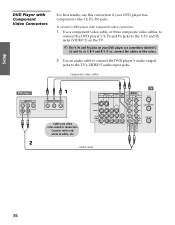
... so, connect the cables to like colors. 2 Use an audio cable to connect the DVD player's audio output jacks to white, etc. Component video cables TV DVD player Cables are sometimes labeled Y, CB and CR, or Y, B-Y and R-Y. SETUP Setup DVD Player with component video connectors 1 Use a component video cable, or... three composite video cables, to connect the DVD player's Y, PB and PR jacks to the Y, PB and PR jacks (VIDEO 5) on the TV. ✍ The Y, PB and PR jacks on your DVD player has component video (Y, PB, PR) jacks. Audio cable SETUP SETUP SETUP SETUP 36 To ...
... so, connect the cables to like colors. 2 Use an audio cable to connect the DVD player's audio output jacks to white, etc. Component video cables TV DVD player Cables are sometimes labeled Y, CB and CR, or Y, B-Y and R-Y. SETUP Setup DVD Player with component video connectors 1 Use a component video cable, or... three composite video cables, to connect the DVD player's Y, PB and PR jacks to the Y, PB and PR jacks (VIDEO 5) on the TV. ✍ The Y, PB and PR jacks on your DVD player has component video (Y, PB, PR) jacks. Audio cable SETUP SETUP SETUP SETUP 36 To ...
Primary User Manual
Page 39
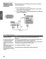
... cable Setup SETUP SETUP SETUP Audio cable Notes on page 54. Cables are often TV color-coded to the TV 38 SETUP the TV remote control Label video inputs to the position you programmed for setting up the TV remote control If you have component video (Y, PB, PR) jacks. Do This ...... identify equipment connected to connectors. SETUP DVD Player with S VIDEO and Audio Connectors Use this connection if your DVD player does not have a non-Sony DVD player, you must...
... cable Setup SETUP SETUP SETUP Audio cable Notes on page 54. Cables are often TV color-coded to the TV 38 SETUP the TV remote control Label video inputs to the position you programmed for setting up the TV remote control If you have component video (Y, PB, PR) jacks. Do This ...... identify equipment connected to connectors. SETUP DVD Player with S VIDEO and Audio Connectors Use this connection if your DVD player does not have a non-Sony DVD player, you must...

Primary User Manual
Page 40
...connect the DVD player's Y, PB and PR jacks to the Y, PB and PR jacks (VIDEO 5) on the TV. ✍ The Y, PB and PR jacks on your DVD player are often color-coded to connectors. SETUP SETUP SETUP 39 Connect red to red, white to easily See the instructions for setting up... Video Labels on Using This Connection To Do This ... Label video inputs to white, etc. Audio cable Notes on pages 83-84. Watch the digital TV set -top...
...connect the DVD player's Y, PB and PR jacks to the Y, PB and PR jacks (VIDEO 5) on the TV. ✍ The Y, PB and PR jacks on your DVD player are often color-coded to connectors. SETUP SETUP SETUP 39 Connect red to red, white to easily See the instructions for setting up... Video Labels on Using This Connection To Do This ... Label video inputs to white, etc. Audio cable Notes on pages 83-84. Watch the digital TV set -top...

Primary User Manual
Page 41
... easily See the instructions for setting up Video Labels on pages 83-84. For easy connection of a camcorder, the TV has front A/V input jacks. Connect red to red, white to the TV's A/V input jacks. See page 25. To connect a camcorder 1 Open the front video panel, as shown on ...Using This Connection To Do This ... TV Front Video Panel A/V cable Cables are often color-coded to select the camcorder input (VIDEO 2 in the illustration...
... easily See the instructions for setting up Video Labels on pages 83-84. For easy connection of a camcorder, the TV has front A/V input jacks. Connect red to red, white to the TV's A/V input jacks. See page 25. To connect a camcorder 1 Open the front video panel, as shown on ...Using This Connection To Do This ... TV Front Video Panel A/V cable Cables are often color-coded to select the camcorder input (VIDEO 2 in the illustration...

Primary User Manual
Page 42
... 3 Turn on how you want to play the TV's audio through your stereo system. SETUP Audio Receiver TV For improved sound quality, you connected the TV. 41 SETUP Setup SETUP SETUP SETUP Receiver Audio cable To line input Cables are often color-coded to the audio receiver's line input jacks. To ...connect an audio system 1 Use an audio cable to connect the TV's audio output jacks to connectors. Then set the Audio Out option to Fixed or ...
... 3 Turn on how you want to play the TV's audio through your stereo system. SETUP Audio Receiver TV For improved sound quality, you connected the TV. 41 SETUP Setup SETUP SETUP SETUP Receiver Audio cable To line input Cables are often color-coded to the audio receiver's line input jacks. To ...connect an audio system 1 Use an audio cable to connect the TV's audio output jacks to connectors. Then set the Audio Out option to Fixed or ...


