
Dimensions Diagram (Front & Top)
Page 1
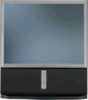
...) 986 3062 • b2b.sel.sony.com Features and specifications subject to change without notice. • Non-metric weights and measurements are approximate. DESCRIPTION: 53" Projection TV DIMENSIONS HD Capable (WHD): 47 15/16 " x 57 1/2 " x 25 " WEIGHT: 185 lbs POWER REQUIREMENTS: 120V AC POWER 60Hz CONSUMPTION: 240 w max 1w stby...REQUIRE A GREAT DEGREE OF PRECISION WE RECOMMEND THAT THE PRODUCT ITSELF BE USED TO MAKE THE ACTUAL MEASUREMENTS. SONY WILL NOT BE RESPONSIBLE FOR INACCURACIES IN THE DESIGN OR MANUFACTURE OF ENCLOSURES . KP-53HS10 NOTE: IR Receiver in "O" of Logo.
...) 986 3062 • b2b.sel.sony.com Features and specifications subject to change without notice. • Non-metric weights and measurements are approximate. DESCRIPTION: 53" Projection TV DIMENSIONS HD Capable (WHD): 47 15/16 " x 57 1/2 " x 25 " WEIGHT: 185 lbs POWER REQUIREMENTS: 120V AC POWER 60Hz CONSUMPTION: 240 w max 1w stby...REQUIRE A GREAT DEGREE OF PRECISION WE RECOMMEND THAT THE PRODUCT ITSELF BE USED TO MAKE THE ACTUAL MEASUREMENTS. SONY WILL NOT BE RESPONSIBLE FOR INACCURACIES IN THE DESIGN OR MANUFACTURE OF ENCLOSURES . KP-53HS10 NOTE: IR Receiver in "O" of Logo.
Operating Instructions
Page 3
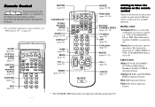
...; Green:Buttons relevant to power operations, like turning the projection TV, DBS/CABLE, or VTR (VCR)/MDP/DVD Player on page 25. SLEEP (page 26) VTR1/2/3/ DVD/MDP switch (page 53) VCR/DVD/ MDP operation buttons (page 54) CODE SET (pages 53, 55) MTS (page 35) POWER MUTING SYSTEM DVD/ DBS TV OFF VTR CABLE VTR123DVD/MDP...
...; Green:Buttons relevant to power operations, like turning the projection TV, DBS/CABLE, or VTR (VCR)/MDP/DVD Player on page 25. SLEEP (page 26) VTR1/2/3/ DVD/MDP switch (page 53) VCR/DVD/ MDP operation buttons (page 54) CODE SET (pages 53, 55) MTS (page 35) POWER MUTING SYSTEM DVD/ DBS TV OFF VTR CABLE VTR123DVD/MDP...
Operating Instructions
Page 6
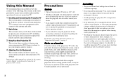
... wait a few hours to let the moisture evaporate before operating it further. • If you will not be using the projection TV for several days, disconnect the power by qualified service personnel before turning on the projection TV. • To obtain the best picture, do not block the ventilation openings. • Do not install the...
... wait a few hours to let the moisture evaporate before operating it further. • If you will not be using the projection TV for several days, disconnect the power by qualified service personnel before turning on the projection TV. • To obtain the best picture, do not block the ventilation openings. • Do not install the...

Operating Instructions
Page 7
...the outlet, contact your electrician to be observed in the installation, use liquid cleaners or aerosol cleaners. Always turn the set from battery power, refer to operate from the wall outlet before cleaning or polishing it is left unattended and unused for future reference. Cleaning Unplug the...short out parts that could result in a fire or electric shock. If the plug should be used. This is a safety feature. Use Power Sources This set should be operated only from the wall outlet as a precaution against injury, the following basic safety precautions should still fail ...
...the outlet, contact your electrician to be observed in the installation, use liquid cleaners or aerosol cleaners. Always turn the set from battery power, refer to operate from the wall outlet before cleaning or polishing it is left unattended and unused for future reference. Cleaning Unplug the...short out parts that could result in a fire or electric shock. If the plug should be used. This is a safety feature. Use Power Sources This set should be operated only from the wall outlet as a precaution against injury, the following basic safety precautions should still fail ...

Operating Instructions
Page 8
...back or bottom are provided for the specific model of projection TV. 4 An appliance and cart combination should not be located in the vicinity of overhead power lines or other electric light or power circuits, or where it from a projection TV set on or roll over a radiator or heat register,... with care. for the grounding electrode. To ensure reliable operation of antenna discharge unit, connection to provide some projection TV sets to the set where the power cord is installed, follow the precautions below. Accessories Do not place the set , and to direct sunlight.
...back or bottom are provided for the specific model of projection TV. 4 An appliance and cart combination should not be located in the vicinity of overhead power lines or other electric light or power circuits, or where it from a projection TV set on or roll over a radiator or heat register,... with care. for the grounding electrode. To ensure reliable operation of antenna discharge unit, connection to provide some projection TV sets to the set where the power cord is installed, follow the precautions below. Accessories Do not place the set , and to direct sunlight.

Operating Instructions
Page 9
... discharge unit (NEC Section 810-20) Grounding conductors (NEC Section 810-21) Electric service equipment NEC: National Electrical Code Ground clamps Power service grounding electrode system (NEC Art 250 Part H) Lightning For added protection for this indicates a need for long periods of time,...to excessive shock by the manufacturer that are required, be sure the service technician certifies in safe operating condition, and to lightning and power-line surges. Unauthorized substitutions may result in fire, electric shock, or other hazards. If the set is damaged or frayed. -...
... discharge unit (NEC Section 810-20) Grounding conductors (NEC Section 810-21) Electric service equipment NEC: National Electrical Code Ground clamps Power service grounding electrode system (NEC Art 250 Part H) Lightning For added protection for this indicates a need for long periods of time,...to excessive shock by the manufacturer that are required, be sure the service technician certifies in safe operating condition, and to lightning and power-line surges. Unauthorized substitutions may result in fire, electric shock, or other hazards. If the set is damaged or frayed. -...

Operating Instructions
Page 13
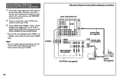
... are connecting a monaural VCR, connect only the single audio output to AUDIO and S VIDEO IN on the projection TV. Disconnect all power sources before making any connections. Installing and Connecting the Projection TV Connecting an Antenna/Cable TV System to a VCR 1 Attach the coaxial cable from the incoming cable connection or antenna to IN on the...
... are connecting a monaural VCR, connect only the single audio output to AUDIO and S VIDEO IN on the projection TV. Disconnect all power sources before making any connections. Installing and Connecting the Projection TV Connecting an Antenna/Cable TV System to a VCR 1 Attach the coaxial cable from the incoming cable connection or antenna to IN on the...
Operating Instructions
Page 14
...which the cable box is connected to AUDIO and S VIDEO IN on the VCR to by pressing TV/VIDEO. S VIDEO Disconnect all power sources before making any connections. (Rear of the S VIDEO cable. Connecting a VCR and Projection TV to a Cable Box 1 Connect the single (input) jack of the splitter to the incoming ...cable connection, and connect the other two (output) jacks (using the coaxial cable) to IN on the cable box and VHF/UHF on the projection TV. 2 Using a coaxial cable, connect OUT on the cable box to IN on the VCR. 3 Using AUDIO and S VIDEO* cables, connect AUDIO and S VIDEO...
...which the cable box is connected to AUDIO and S VIDEO IN on the VCR to by pressing TV/VIDEO. S VIDEO Disconnect all power sources before making any connections. (Rear of the S VIDEO cable. Connecting a VCR and Projection TV to a Cable Box 1 Connect the single (input) jack of the splitter to the incoming ...cable connection, and connect the other two (output) jacks (using the coaxial cable) to IN on the cable box and VHF/UHF on the projection TV. 2 Using a coaxial cable, connect OUT on the cable box to IN on the VCR. 3 Using AUDIO and S VIDEO* cables, connect AUDIO and S VIDEO...

Operating Instructions
Page 15
...HD and VD respectively of the DTV receiver. Installing and Connecting the Projection TV Connecting a DTV (Digital Television) Receiver Before connecting, be sure to read the Operating Instructions of VIDEO 5 (DTV) IN on page 43) Disconnect all power sources before making any connections. 2 Composite video cable for DTV receiver... an AUDIO cable, connect AUDIO OUT on the DTV receiver to AUDIO of VIDEO 5 (DTV) IN on the projection TV (WhiteAUDIO Left, Red-AUDIO Right). 4 Select VIDEO 5 by the TV/VIDEO button. 5 Select the SET UP menu and set DTV INPUT to R.G.B. (see "DTV INPUT" on the...
...HD and VD respectively of the DTV receiver. Installing and Connecting the Projection TV Connecting a DTV (Digital Television) Receiver Before connecting, be sure to read the Operating Instructions of VIDEO 5 (DTV) IN on page 43) Disconnect all power sources before making any connections. 2 Composite video cable for DTV receiver... an AUDIO cable, connect AUDIO OUT on the DTV receiver to AUDIO of VIDEO 5 (DTV) IN on the projection TV (WhiteAUDIO Left, Red-AUDIO Right). 4 Select VIDEO 5 by the TV/VIDEO button. 5 Select the SET UP menu and set DTV INPUT to R.G.B. (see "DTV INPUT" on the...

Operating Instructions
Page 16
...) to Y. Connect PB (blue) to Y PB PR. (see "DTV INPUT" on the projection TV (WhiteAUDIO Left, Red-AUDIO Right). 4 Select VIDEO 5 by the TV/VIDEO button. 5 Select the SET UP menu and set DTV INPUT to CB, Cb or B-Y. Disconnect all power sources before making any connections. 2 VMC-10HG (not supplied) PB Y PR CONTROL... three VIDEO cables, connect Y, PB and PR of COMPONENT VIDEO OUT on the DTV receiver to Y, PB and PR of VIDEO 5 (DTV) IN on the projection TV. 3 Using an AUDIO cable, connect LINE OUT on the DTV receiver to AUDIO of VIDEO 5 (DTV) IN on page 43) Note: • Some DTV ...
...) to Y. Connect PB (blue) to Y PB PR. (see "DTV INPUT" on the projection TV (WhiteAUDIO Left, Red-AUDIO Right). 4 Select VIDEO 5 by the TV/VIDEO button. 5 Select the SET UP menu and set DTV INPUT to CB, Cb or B-Y. Disconnect all power sources before making any connections. 2 VMC-10HG (not supplied) PB Y PR CONTROL... three VIDEO cables, connect Y, PB and PR of COMPONENT VIDEO OUT on the DTV receiver to Y, PB and PR of VIDEO 5 (DTV) IN on the projection TV. 3 Using an AUDIO cable, connect LINE OUT on the DTV receiver to AUDIO of VIDEO 5 (DTV) IN on page 43) Note: • Some DTV ...

Operating Instructions
Page 17
Disconnect all power sources before making any connections. (Rear of projection TV) CONTROL S IN OUT AUX IN OUT VIDEO 4 VIDEO 5 (DTV) SELECT IN VIDEO 1 VIDEO 3 HD VD Cable/ Satellite antenna Antenna cable 21 S VIDEO VIDEO L (MONO) AUDIO R Y ... AUDIO and S VIDEO cables, connect AUDIO and S VIDEO OUT on the DBS receiver to by pressing TV/VIDEO on the projection TV (White-AUDIO Left, RedAUDIO Right). Installing and Connecting the Projection TV Connecting a DBS (Direct Broadcast Satellite) Receiver 1 Connect the cable from the satellite antenna to the DBS receiver. 2 Attach the ...
Disconnect all power sources before making any connections. (Rear of projection TV) CONTROL S IN OUT AUX IN OUT VIDEO 4 VIDEO 5 (DTV) SELECT IN VIDEO 1 VIDEO 3 HD VD Cable/ Satellite antenna Antenna cable 21 S VIDEO VIDEO L (MONO) AUDIO R Y ... AUDIO and S VIDEO cables, connect AUDIO and S VIDEO OUT on the DBS receiver to by pressing TV/VIDEO on the projection TV (White-AUDIO Left, RedAUDIO Right). Installing and Connecting the Projection TV Connecting a DBS (Direct Broadcast Satellite) Receiver 1 Connect the cable from the satellite antenna to the DBS receiver. 2 Attach the ...

Operating Instructions
Page 18
...AUDIO and S VIDEO* cables, connect AUDIO and S VIDEO OUT on the VCR to AUDIO and S VIDEO IN on the projection TV (White-AUDIO Left, Red-AUDIO Right). * If your DBS receiver or VCR is connected to the satellite receiver. 2 Attach... the video input which your VCR or DBS receiver is not equipped with S VIDEO, use a VIDEO cable (yellow) instead of projection TV) CONTROL S IN OUT AUX IN OUT VIDEO 4 VIDEO 5 (DTV) SELECT IN VIDEO 1 VIDEO 3 HD VD Coaxial cable ... (not supplied) Cable/ Antenna 2 YC-15V/30V (not supplied) 14 Disconnect all power sources before making any connections.
...AUDIO and S VIDEO* cables, connect AUDIO and S VIDEO OUT on the VCR to AUDIO and S VIDEO IN on the projection TV (White-AUDIO Left, Red-AUDIO Right). * If your DBS receiver or VCR is connected to the satellite receiver. 2 Attach... the video input which your VCR or DBS receiver is not equipped with S VIDEO, use a VIDEO cable (yellow) instead of projection TV) CONTROL S IN OUT AUX IN OUT VIDEO 4 VIDEO 5 (DTV) SELECT IN VIDEO 1 VIDEO 3 HD VD Coaxial cable ... (not supplied) Cable/ Antenna 2 YC-15V/30V (not supplied) 14 Disconnect all power sources before making any connections.

Operating Instructions
Page 19
...AUDIO-L AUDIO-R VMC-810S/820S (not supplied) 1 Audio/video outputs YC-15V/30V (not supplied) 1 Camcorder 15 Installing and Connecting the Projection TV Connecting a Camcorder Use this connection to view a picture directly from your camcorder. 1 Using AUDIO and S VIDEO* cables, connect AUDIO and .... * If your camcorder is not equipped with S VIDEO, use a VIDEO cable (yellow) instead of projection TV) S VIDEO Push to the left (MONO) input on the projection TV. Disconnect all power sources before making any connections. (Front of the S VIDEO cable. **If you are connecting a monaural ...
...AUDIO-L AUDIO-R VMC-810S/820S (not supplied) 1 Audio/video outputs YC-15V/30V (not supplied) 1 Camcorder 15 Installing and Connecting the Projection TV Connecting a Camcorder Use this connection to view a picture directly from your camcorder. 1 Using AUDIO and S VIDEO* cables, connect AUDIO and .... * If your camcorder is not equipped with S VIDEO, use a VIDEO cable (yellow) instead of projection TV) S VIDEO Push to the left (MONO) input on the projection TV. Disconnect all power sources before making any connections. (Front of the S VIDEO cable. **If you are connecting a monaural ...

Operating Instructions
Page 20
... VCR LINE INPUT (see "SELECT OUT" on page 41) 16 VCR (for playback) AUDIO R AUDIO L VIDEO LINE OUT OUT IN 1 Disconnect all power sources before making any connections. (Rear of projection TV) CONTROL S IN OUT AUX IN OUT VIDEO 4 VIDEO 5 (DTV) SELECT IN VIDEO 1 VIDEO 3 HD VD S VIDEO VIDEO L (MONO) AUDIO R Y ... for recording) R AUDIO R AUDIO L VIDEO LINE IN OUT IN 2 VMC-810S/820S (not supplied) VMC-810S/820S (not supplied) (Rear of projection TV) VIDEO IN SELECT OUT Indicates direction of this manual. 2 Using an AUDIO/VIDEO cable, connect AUDIO and VIDEO IN on the...
... VCR LINE INPUT (see "SELECT OUT" on page 41) 16 VCR (for playback) AUDIO R AUDIO L VIDEO LINE OUT OUT IN 1 Disconnect all power sources before making any connections. (Rear of projection TV) CONTROL S IN OUT AUX IN OUT VIDEO 4 VIDEO 5 (DTV) SELECT IN VIDEO 1 VIDEO 3 HD VD S VIDEO VIDEO L (MONO) AUDIO R Y ... for recording) R AUDIO R AUDIO L VIDEO LINE IN OUT IN 2 VMC-810S/820S (not supplied) VMC-810S/820S (not supplied) (Rear of projection TV) VIDEO IN SELECT OUT Indicates direction of this manual. 2 Using an AUDIO/VIDEO cable, connect AUDIO and VIDEO IN on the...

Operating Instructions
Page 21
...the DVD Player through other video equipment will cause unwanted picture noise. 17 Installing and Connecting the Projection TV Connecting a DVD Player With S Video or Composite Video Output Connectors Using an AUDIO and S VIDEO cables, connect... AUDIO and S VIDEO IN on the projection TV to the projection TV. Note: • Since the high quality pictures on a DVD disc contain a lot of projection TV) CONTROL S IN OUT AUX IN OUT VIDEO 4 VIDEO 5 (DTV) SELECT... to AUDIO and S VIDEO OUT on page 35) Disconnect all power sources before making any connections.
...the DVD Player through other video equipment will cause unwanted picture noise. 17 Installing and Connecting the Projection TV Connecting a DVD Player With S Video or Composite Video Output Connectors Using an AUDIO and S VIDEO cables, connect... AUDIO and S VIDEO IN on the projection TV to the projection TV. Note: • Since the high quality pictures on a DVD disc contain a lot of projection TV) CONTROL S IN OUT AUX IN OUT VIDEO 4 VIDEO 5 (DTV) SELECT... to AUDIO and S VIDEO OUT on page 35) Disconnect all power sources before making any connections.

Operating Instructions
Page 22
...on a DVD disc contain a lot of information, picture noise may be labeled differently. If so, connect as follows: Connect Y (green) to the projection TV. PR PB (Rear of projection TV) Y CONTROL S IN OUT IN OUT VIDEO 4 VIDEO 5 (DTV) SELECT VMC-10HG (not supplied) AUX IN VIDEO 1 VIDEO 3 HD VD ... on page 35) Disconnect all power sources before making any connections. Connecting the DVD Player through other video equipment will cause unwanted picture noise. 18 Connect PB (blue) to Y, PB and PR of VIDEO 4 IN or VIDEO 5 (DTV) IN on the projection TV. Connecting a DVD Player With...
...on a DVD disc contain a lot of information, picture noise may be labeled differently. If so, connect as follows: Connect Y (green) to the projection TV. PR PB (Rear of projection TV) Y CONTROL S IN OUT IN OUT VIDEO 4 VIDEO 5 (DTV) SELECT VMC-10HG (not supplied) AUX IN VIDEO 1 VIDEO 3 HD VD ... on page 35) Disconnect all power sources before making any connections. Connecting the DVD Player through other video equipment will cause unwanted picture noise. 18 Connect PB (blue) to Y, PB and PR of VIDEO 4 IN or VIDEO 5 (DTV) IN on the projection TV. Connecting a DVD Player With...

Operating Instructions
Page 23
... control of all power sources before making any connections. Coaxial cable (not supplied) VMC-810S/820S (not supplied) (Rear of VIDEO 1 IN on the projection TV to MONITOR OUT on the AV receiver. 4 Using an AUDIO/VIDEO cable, connect SELECT OUT on the projection TV to AUDIO/VIDEO ... FIX" on page 38) Disconnect all audio and video equipment, connect an AV receiver. 1-2Perform as described on page 9. 3 Using a VIDEO cable, connect VIDEO of projection TV) 2 CONTROL S IN OUT AUX IN OUT VIDEO 4 VIDEO 5 (DTV) SELECT IN VIDEO 1 VIDEO 3 HD VD S VIDEO VIDEO L (MONO) AUDIO R Y Y/G L PB...
... control of all power sources before making any connections. Coaxial cable (not supplied) VMC-810S/820S (not supplied) (Rear of VIDEO 1 IN on the projection TV to MONITOR OUT on the AV receiver. 4 Using an AUDIO/VIDEO cable, connect SELECT OUT on the projection TV to AUDIO/VIDEO ... FIX" on page 38) Disconnect all audio and video equipment, connect an AV receiver. 1-2Perform as described on page 9. 3 Using a VIDEO cable, connect VIDEO of projection TV) 2 CONTROL S IN OUT AUX IN OUT VIDEO 4 VIDEO 5 (DTV) SELECT IN VIDEO 1 VIDEO 3 HD VD S VIDEO VIDEO L (MONO) AUDIO R Y Y/G L PB...

Operating Instructions
Page 24
...sound, connect an audio system to the projection TV. 1 Using an AUDIO cable, connect AUDIO (VAR) OUT on the projection TV to switch the projection TV's speakers off. (see "SPEAKER" on page 36) Note: • You can adjust VOLUME, BASS, TREBLE and BALANCE through the projection TV on the stereo (White-AUDIO Left, ...RedAUDIO Right). 2 Set the stereo to the chosen Line input and use the AUDIO menu to one of projection TV) AUDIO OUT FIX VAR L R AUDIO (VAR) OUT-L 1 AUDIO (VAR) OUT-R RK-74A (not supplied) Line input HRD Stereo amplifier Tape-2, AUX1,...
...sound, connect an audio system to the projection TV. 1 Using an AUDIO cable, connect AUDIO (VAR) OUT on the projection TV to switch the projection TV's speakers off. (see "SPEAKER" on page 36) Note: • You can adjust VOLUME, BASS, TREBLE and BALANCE through the projection TV on the stereo (White-AUDIO Left, ...RedAUDIO Right). 2 Set the stereo to the chosen Line input and use the AUDIO menu to one of projection TV) AUDIO OUT FIX VAR L R AUDIO (VAR) OUT-L 1 AUDIO (VAR) OUT-R RK-74A (not supplied) Line input HRD Stereo amplifier Tape-2, AUX1,...

Operating Instructions
Page 25
... (FIX) OUT-L AUDIO (FIX) OUT-R 2 RK-74A (not supplied) Line input 3 Amplifier with the amplifier), connect the speaker terminals on the projection TV to one of the unused Line inputs (e.g. Tape-2, AUX1, etc.) on the amplifier (White-AUDIO Left, red-AUDIO Right). 3 Set the amplifier to... AUDIO (FIX) OUT on the amplifier to "CENTER IN" on the projection TV. (see "SPEAKER" on page 36) Disconnect all power sources before making any connections. (Rear of the projection TV's audio system, you use the projection TV's speaker as a center speaker. 1 Using the speaker cords (supplied with...
... (FIX) OUT-L AUDIO (FIX) OUT-R 2 RK-74A (not supplied) Line input 3 Amplifier with the amplifier), connect the speaker terminals on the projection TV to one of the unused Line inputs (e.g. Tape-2, AUX1, etc.) on the amplifier (White-AUDIO Left, red-AUDIO Right). 3 Set the amplifier to... AUDIO (FIX) OUT on the amplifier to "CENTER IN" on the projection TV. (see "SPEAKER" on page 36) Disconnect all power sources before making any connections. (Rear of the projection TV's audio system, you use the projection TV's speaker as a center speaker. 1 Using the speaker cords (supplied with...

Operating Instructions
Page 27
..., CHANNEL - YES: [CH +] NO : [CH -] (continued) 23 Basic Set Up Setting Up the Projection TV Automatically The AUTO SET UP feature will allow you to turn on the projection TV. The AUTO SET UP feature does not apply for installations that the input from ANT (not AUX) is selected... FLASH FOCUS S VIDEO VIDEO L(MONO) AUDIO R SET UP VIDEO 2 INPUT 1 Press POWER to set all channel selection. POWER 2 Press SET UP inside the lower front panel on -screen language and set the on the projection TV: POWER TIMER/STAND BY STEREO + CHANNEL - + VOLUME - The AUTO SET UP screen appears. to ...
..., CHANNEL - YES: [CH +] NO : [CH -] (continued) 23 Basic Set Up Setting Up the Projection TV Automatically The AUTO SET UP feature will allow you to turn on the projection TV. The AUTO SET UP feature does not apply for installations that the input from ANT (not AUX) is selected... FLASH FOCUS S VIDEO VIDEO L(MONO) AUDIO R SET UP VIDEO 2 INPUT 1 Press POWER to set all channel selection. POWER 2 Press SET UP inside the lower front panel on -screen language and set the on the projection TV: POWER TIMER/STAND BY STEREO + CHANNEL - + VOLUME - The AUTO SET UP screen appears. to ...


