Service Manual
Page 1
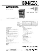
SERVICE MANUAL Ver. 1.5 2007.04 HCD-NEZ30 US Model Canadian Model UK Model E Model East European Model • HCD-NEZ30 is the value measurement at 1 kHz, 10% THD) Inputs AUDIO IN: Sensitivity 250 mV, impedance 47 kilohms Outputs PHONES: Accepts headphones...are subject to 16 ohms CD player section System: Compact disc and digital audio system Laser Diode Properties Emission Duration: Continuous Laser Output*: Less than 10% total harmonic distortion from 120 - 10,000 Hz; COMPACT DISC DECK RECEIVER 9-887-030-06 2007D05-1 © 2007.04 Sony Corporation Personal Audio Division ...
SERVICE MANUAL Ver. 1.5 2007.04 HCD-NEZ30 US Model Canadian Model UK Model E Model East European Model • HCD-NEZ30 is the value measurement at 1 kHz, 10% THD) Inputs AUDIO IN: Sensitivity 250 mV, impedance 47 kilohms Outputs PHONES: Accepts headphones...are subject to 16 ohms CD player section System: Compact disc and digital audio system Laser Diode Properties Emission Duration: Continuous Laser Output*: Less than 10% total harmonic distortion from 120 - 10,000 Hz; COMPACT DISC DECK RECEIVER 9-887-030-06 2007D05-1 © 2007.04 Sony Corporation Personal Audio Division ...

Service Manual
Page 2
... to apply force on the rear exterior. SAFETY CHECK-OUT After correcting the original service problem, perform the following safety check before releasing the set to the customer: Check... V AC range are examples of a passive VOM that is suitable. HCD-NEZ30 Notes on chip component replacement • Never reuse a disconnected chip component. • Notice that have an accurate low-voltage scale. A commercial...or RCA WT-540A. REPLACE THESE COMPONENTS WITH SONY PARTS WHOSE PART NUMBERS APPEAR AS SHOWN IN THIS MANUAL OR IN SUPPLEMENTS PUBLISHED BY SONY. 2 ATTENTION AU COMPOSANT AYANT ...
... to apply force on the rear exterior. SAFETY CHECK-OUT After correcting the original service problem, perform the following safety check before releasing the set to the customer: Check... V AC range are examples of a passive VOM that is suitable. HCD-NEZ30 Notes on chip component replacement • Never reuse a disconnected chip component. • Notice that have an accurate low-voltage scale. A commercial...or RCA WT-540A. REPLACE THESE COMPONENTS WITH SONY PARTS WHOSE PART NUMBERS APPEAR AS SHOWN IN THIS MANUAL OR IN SUPPLEMENTS PUBLISHED BY SONY. 2 ATTENTION AU COMPOSANT AYANT ...
Service Manual
Page 3
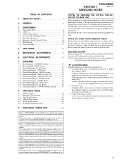
...service manual/SUPPLEMENT-2 according to ordinary solder. 3 SERVICING NOTES 3 2. Disassembly Flow 8 3-2. Front Panel Section 10 3-6. MAIN Section 18 7-3. Printed Wiring Boards - Schematic Diagram - MAIN Section (2/2 24 7-8. EXPLODED VIEWS 8-1. Panel Board Section 38 8-4. When repairing the set . HCD-NEZ30 SECTION 1 Ver. 1.5 SERVICING... schematic diagram and electrical parts list of UK and East European models. GENERAL 6 3. CD Board 20 7-4. Mechanical Deck Section 37 8-3. Soldering irons using a temperature regulator should be handled with ordinary solder It...
...service manual/SUPPLEMENT-2 according to ordinary solder. 3 SERVICING NOTES 3 2. Disassembly Flow 8 3-2. Front Panel Section 10 3-6. MAIN Section 18 7-3. Printed Wiring Boards - Schematic Diagram - MAIN Section (2/2 24 7-8. EXPLODED VIEWS 8-1. Panel Board Section 38 8-4. When repairing the set . HCD-NEZ30 SECTION 1 Ver. 1.5 SERVICING... schematic diagram and electrical parts list of UK and East European models. GENERAL 6 3. CD Board 20 7-4. Mechanical Deck Section 37 8-3. Soldering irons using a temperature regulator should be handled with ordinary solder It...
Service Manual
Page 6
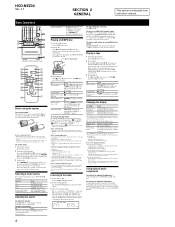
... to avoid damage from instruction manual. Press / on the unit. Component (connected FUNCTION repeatedly using a...HCD-NEZ30 Ver. 1.1 SECTION 2 GENERAL This section is extracted from battery leakage and corrosion. Basic Operations *Except for the North American model Before using uppercase letters (A to Z), numbers (0 to 9), and symbols Using optional audio components... display modes. To select Press CD CD on the remote. Tuner TUNER/BAND...the tape or the tape deck. The system offers the... and file names that provides RDS services, the station name appears on the unit...
... to avoid damage from instruction manual. Press / on the unit. Component (connected FUNCTION repeatedly using a...HCD-NEZ30 Ver. 1.1 SECTION 2 GENERAL This section is extracted from battery leakage and corrosion. Basic Operations *Except for the North American model Before using uppercase letters (A to Z), numbers (0 to 9), and symbols Using optional audio components... display modes. To select Press CD CD on the remote. Tuner TUNER/BAND...the tape or the tape deck. The system offers the... and file names that provides RDS services, the station name appears on the unit...
Service Manual
Page 20
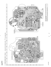
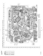
HCD-NEZ30 Ver. 1.5 7-3. CD Board - • See page 19 for Circuit Boards Location. : Uses unleaded solder. 1 2 3 4 5 6 7 8 9 10 A CD BOARD (COMPONENT SIDE) C401 B C R401 D C201 R201 E C202 C424 C101 C102 C108 C110 R207 R202 C203 R423 C406 R421 C272 C104 C109 C271 C105 ... 22) C111 20 20 OPTICAL PICK-UP BLOCK KSM-213CDP 11 1-868-067- (11) Refer to SUPPLEMENT-1 for the CD board of printed wiring board of original service manual/SUPPLEMENT-1 according to either of UK and East European models. When repairing the set of except UK and East European models,...
HCD-NEZ30 Ver. 1.5 7-3. CD Board - • See page 19 for Circuit Boards Location. : Uses unleaded solder. 1 2 3 4 5 6 7 8 9 10 A CD BOARD (COMPONENT SIDE) C401 B C R401 D C201 R201 E C202 C424 C101 C102 C108 C110 R207 R202 C203 R423 C406 R421 C272 C104 C109 C271 C105 ... 22) C111 20 20 OPTICAL PICK-UP BLOCK KSM-213CDP 11 1-868-067- (11) Refer to SUPPLEMENT-1 for the CD board of printed wiring board of original service manual/SUPPLEMENT-1 according to either of UK and East European models. When repairing the set of except UK and East European models,...
Service Manual
Page 21
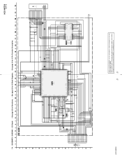
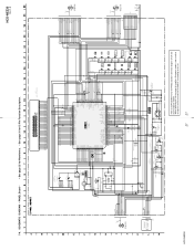
...IC Block Diagrams. • See page 31 for the CD board of schematic diagram of original service manual/SUPPLEMENT-1 according to the set of except UK and East European models, refer to SUPPLEMENT-1 for IC Pin Function Description. VC VCC E D A B C F GND LD VR PD F+ T+ TF- HCD-NEZ30 Ver. 1.5 (Page 23) DATA CLK-MP3 M-MUTE...PREVCC CH4OUTR CH4OUTF CH3OUTF CH3OUTR POWVCC MUTE GND C405 0.1 SPSP+ SLSL+ C406 0.1 S201 (LIMIT) OPTICAL PICK-UP BLOCK KSM-213CDP M401 (SPINDLE) M402 (SLED) HCD-NEZ30 Refer to either of UK and East European models. When repairing the set . 21 21
...IC Block Diagrams. • See page 31 for the CD board of schematic diagram of original service manual/SUPPLEMENT-1 according to the set of except UK and East European models, refer to SUPPLEMENT-1 for IC Pin Function Description. VC VCC E D A B C F GND LD VR PD F+ T+ TF- HCD-NEZ30 Ver. 1.5 (Page 23) DATA CLK-MP3 M-MUTE...PREVCC CH4OUTR CH4OUTF CH3OUTF CH3OUTR POWVCC MUTE GND C405 0.1 SPSP+ SLSL+ C406 0.1 S201 (LIMIT) OPTICAL PICK-UP BLOCK KSM-213CDP M401 (SPINDLE) M402 (SLED) HCD-NEZ30 Refer to either of UK and East European models. When repairing the set . 21 21
Service Manual
Page 22
...-180- (11) • Semiconductor Location Ref. Location Ref. No. Location Ref. No. HCD-NEZ30 When repairing the set of US and Canadian models, refer to either of original service manual/ SUPPLEMENT-2 according to the set . 22 22 Refer to SUPPLEMENT-2 for the HEAD PHONE board... East European models, refer to either of original service manual/SUPPLEMENT-1 according to SUPPLEMENT-1 for Circuit Boards Location. : Uses unleaded solder. 1 2 3 4 5 6 7 8 9 10 11 12 13 14 15 MAIN BOARD A (Page 26) D PANEL BOARD (Page 20) A CD BOARD CN102 (Page 28) B DC BOARD CN903...
...-180- (11) • Semiconductor Location Ref. Location Ref. No. Location Ref. No. HCD-NEZ30 When repairing the set of US and Canadian models, refer to either of original service manual/ SUPPLEMENT-2 according to the set . 22 22 Refer to SUPPLEMENT-2 for the HEAD PHONE board... East European models, refer to either of original service manual/SUPPLEMENT-1 according to SUPPLEMENT-1 for Circuit Boards Location. : Uses unleaded solder. 1 2 3 4 5 6 7 8 9 10 11 12 13 14 15 MAIN BOARD A (Page 26) D PANEL BOARD (Page 20) A CD BOARD CN102 (Page 28) B DC BOARD CN903...
Service Manual
Page 23
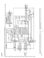
MAIN Section (1/2) - HCD-NEZ30 Ver. 1.1 (Page 24) A1 A2 A4 A5 A6 A7 A8 J321 AUDIO IN R236 10k C226 220p... 1k R386 100 R391 R392 D324 UDZSTE-174.7B D320 MC2840-T112-1 R521 10k R517 47k D307 1SS355TE CD-R C238 22 50V CD-L C138 22 50V SCOR SENS XLAT MP3-ACK MP3-O-REQ MP3-XLAT MP3-DATA CLK MP3-I-REQ XRST ...HPGND SP-L SP-L SP-L HP-L HP-L HP-L CN500 13P (Page 24) (Page 24) HCD-NEZ30 23 23 Refer to SUPPLEMENT-1 for the MAIN board of schematic diagram of original service manual/SUPPLEMENT-1 according to either of except US and Canadian models. When repairing the set of US ...
MAIN Section (1/2) - HCD-NEZ30 Ver. 1.1 (Page 24) A1 A2 A4 A5 A6 A7 A8 J321 AUDIO IN R236 10k C226 220p... 1k R386 100 R391 R392 D324 UDZSTE-174.7B D320 MC2840-T112-1 R521 10k R517 47k D307 1SS355TE CD-R C238 22 50V CD-L C138 22 50V SCOR SENS XLAT MP3-ACK MP3-O-REQ MP3-XLAT MP3-DATA CLK MP3-I-REQ XRST ...HPGND SP-L SP-L SP-L HP-L HP-L HP-L CN500 13P (Page 24) (Page 24) HCD-NEZ30 23 23 Refer to SUPPLEMENT-1 for the MAIN board of schematic diagram of original service manual/SUPPLEMENT-1 according to either of except US and Canadian models. When repairing the set of US ...
Service Manual
Page 24
.... • See page 25 for IC Block Diagrams. FM 75Ω COAXIAL ANTENNA AM (2/2) R135 100k R235 100k C235 10 50V C135 10 50V CD-L CD-R R226 0 R126 0 R125 22k R225 22k R232 1k R233 0 R228 1k R132 C233 R243 1k 0.047 10k R224 R245 22k 0 R147 22k R118...except UK and East European models, refer to either of except US and Canadian models. HCD-NEZ30 Ver. 1.5 7-7. When repairing the set . HCD-NEZ30 24 Refer to SUPPLEMENT-1 for the HEAD PHONE board of schematic diagram of original service manual/ SUPPLEMENT-2 according to the set of US and Canadian models, refer to either of...
.... • See page 25 for IC Block Diagrams. FM 75Ω COAXIAL ANTENNA AM (2/2) R135 100k R235 100k C235 10 50V C135 10 50V CD-L CD-R R226 0 R126 0 R125 22k R225 22k R232 1k R233 0 R228 1k R132 C233 R243 1k 0.047 10k R224 R245 22k 0 R147 22k R118...except UK and East European models, refer to either of except US and Canadian models. HCD-NEZ30 Ver. 1.5 7-7. When repairing the set . HCD-NEZ30 24 Refer to SUPPLEMENT-1 for the HEAD PHONE board of schematic diagram of original service manual/ SUPPLEMENT-2 according to the set of US and Canadian models, refer to either of...
Service Manual
Page 26
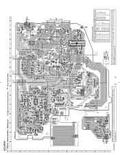
... of UK and East European models. TAPE MECHANISM DECK BLOCK SUPPLIED WITH THE ASSEMBLED BLOCK 26 26 Location D801 G-7 D804 C-4 D805 C-4 D806 F-8 D807 C-9 D809 D-9 IC801 D-7 IC802 E-9 IC803 D-9 Q801 C-8 Q802 G-5 Q803 H-5 Q804 G-5 Q805 G-5 Q807 B-8 Q808 C-4 HCD-NEZ30 7-8. No. When repairing the set . PRINTED ...CD JW850 JW851 JW852 JW867 JW868 JW869 JW870 C806 R849 JW871 1 6 FFC801 JW877 S801 JW875 JW874 C808 JW873 JW872 S808 TAPE 1-869-181- 11, 12, 13 (11, 12, 13) Refer to the set of except UK and East European models, refer to either of original service manual...
... of UK and East European models. TAPE MECHANISM DECK BLOCK SUPPLIED WITH THE ASSEMBLED BLOCK 26 26 Location D801 G-7 D804 C-4 D805 C-4 D806 F-8 D807 C-9 D809 D-9 IC801 D-7 IC802 E-9 IC803 D-9 Q801 C-8 Q802 G-5 Q803 H-5 Q804 G-5 Q805 G-5 Q807 B-8 Q808 C-4 HCD-NEZ30 7-8. No. When repairing the set . PRINTED ...CD JW850 JW851 JW852 JW867 JW868 JW869 JW870 C806 R849 JW871 1 6 FFC801 JW877 S801 JW875 JW874 C808 JW873 JW872 S808 TAPE 1-869-181- 11, 12, 13 (11, 12, 13) Refer to the set of except UK and East European models, refer to either of original service manual...
Service Manual
Page 27
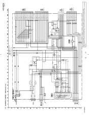
...service manual/SUPPLEMENT-3 according to SUPPLEMENT-3 for IC Pin Function Description. PANEL Board - • See page 25 for Waveforms. • See page 31 for the PANEL board of schematic diagram of UK and East European models. LCD801 LIQUID CRYSTAL DISPLAY HCD-NEZ30...ACDET POWER-ON I-PWR.MONI M-GND M+10V 1 TAPE MECHANISM DECK BLOCK SUPPLIED WITH THE ASSEMBLED BLOCK 1 REC PACK MOTOR10V R849...16V 9 C812 470p R815 1k REMOTE CONTROL RECEIVER R805 0 R863 100 R841 1k D806 ...1 GND 2 FFC804 (Page 24) (NC) S820 CD LID OPEN/CLOSE DETECT HCD-NEZ30 Refer to the set. 27 27 S807 + 31 6...
...service manual/SUPPLEMENT-3 according to SUPPLEMENT-3 for IC Pin Function Description. PANEL Board - • See page 25 for Waveforms. • See page 31 for the PANEL board of schematic diagram of UK and East European models. LCD801 LIQUID CRYSTAL DISPLAY HCD-NEZ30...ACDET POWER-ON I-PWR.MONI M-GND M+10V 1 TAPE MECHANISM DECK BLOCK SUPPLIED WITH THE ASSEMBLED BLOCK 1 REC PACK MOTOR10V R849...16V 9 C812 470p R815 1k REMOTE CONTROL RECEIVER R805 0 R863 100 R841 1k D806 ...1 GND 2 FFC804 (Page 24) (NC) S820 CD LID OPEN/CLOSE DETECT HCD-NEZ30 Refer to the set. 27 27 S807 + 31 6...
Service Manual
Page 42
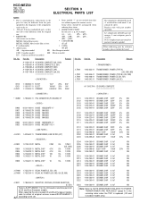
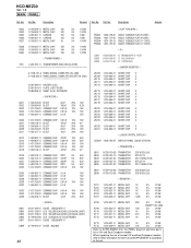
...CERAMIC CHIP 0.1uF 16V Note: Refer to the set. specified in the diagrams or the components Some delay should be different from the original In each case, u: µ, for example... (VOLTAGE SELECTOR) (E, E51) Refer to SUPPLEMENT-1 for the CD board of electrical parts list of original service manual/SUPPLEMENT-1 42 according to "NOTE WHEN PARTS RELATED TO POWER TRANSFORMER ARE REPLACED" (page... list may have some difference from the parts are critical for safety. Part No. HCD-NEZ30 Ver. 1.5 AC CD SECTION 9 ELECTRICAL PARTS LIST NOTE: • Due to standardization, replacements in the ...
...CERAMIC CHIP 0.1uF 16V Note: Refer to the set. specified in the diagrams or the components Some delay should be different from the original In each case, u: µ, for example... (VOLTAGE SELECTOR) (E, E51) Refer to SUPPLEMENT-1 for the CD board of electrical parts list of original service manual/SUPPLEMENT-1 42 according to "NOTE WHEN PARTS RELATED TO POWER TRANSFORMER ARE REPLACED" (page... list may have some difference from the parts are critical for safety. Part No. HCD-NEZ30 Ver. 1.5 AC CD SECTION 9 ELECTRICAL PARTS LIST NOTE: • Due to standardization, replacements in the ...
Service Manual
Page 44
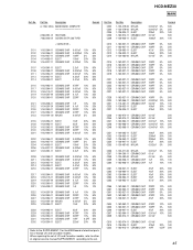
... > R901 1-216-837-11 METAL CHIP 22K 5% 1/10W Note: Refer to "NOTE WHEN PARTS RELATED TO POWER TRANSFORMER ARE REPLACED" (page 4) in the servicing notes when the complete DC board, D921, R911, R912 or R920 is replaced. (US and Canadian models only) 44 C551 1-162-974-11 CERAMIC CHIP...-11 METAL CHIP 10K 5% 1/10W Refer to the set of except UK and East European models, refer to either of original service manual/SUPPLEMENT-2 according to SUPPLEMENT-2 for the HEAD PHONE board of electrical parts list of UK and East European models. No. Part No. HCD-NEZ30 Ver. 1.5 DC HEAD PHONE Ref.
... > R901 1-216-837-11 METAL CHIP 22K 5% 1/10W Note: Refer to "NOTE WHEN PARTS RELATED TO POWER TRANSFORMER ARE REPLACED" (page 4) in the servicing notes when the complete DC board, D921, R911, R912 or R920 is replaced. (US and Canadian models only) 44 C551 1-162-974-11 CERAMIC CHIP...-11 METAL CHIP 10K 5% 1/10W Refer to the set of except UK and East European models, refer to either of original service manual/SUPPLEMENT-2 according to SUPPLEMENT-2 for the HEAD PHONE board of electrical parts list of UK and East European models. No. Part No. HCD-NEZ30 Ver. 1.5 DC HEAD PHONE Ref.
Service Manual
Page 45
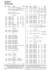
... 220uF 20% 50V 10% 50V 10% 50V 0.5PF 50V 20% 16V Refer to the SUPPLEMENT-1 for the MAIN board of electrical parts list of original service manual/SUPPLEMENT-1 according to the set of US and Canadian models, refer to either of except US and Canadian models. No. Ref. C303 C304 C305 C306... 0.01uF 50V 1-162-974-11 CERAMIC CHIP 0.01uF 1-126-935-11 ELECT 470uF 1-162-915-11 CERAMIC CHIP 10PF 50V 20% 16V 0.5PF 50V 45 HCD-NEZ30 MAIN Ref.
... 220uF 20% 50V 10% 50V 10% 50V 0.5PF 50V 20% 16V Refer to the SUPPLEMENT-1 for the MAIN board of electrical parts list of original service manual/SUPPLEMENT-1 according to the set of US and Canadian models, refer to either of except US and Canadian models. No. Ref. C303 C304 C305 C306... 0.01uF 50V 1-162-974-11 CERAMIC CHIP 0.01uF 1-126-935-11 ELECT 470uF 1-162-915-11 CERAMIC CHIP 10PF 50V 20% 16V 0.5PF 50V 45 HCD-NEZ30 MAIN Ref.
Service Manual
Page 48
... 1K R715 1-216-809-11 METAL CHIP 100 5% 1/10W 5% 1/10W Refer to SUPPLEMENT-3 for the PANEL board of electrical parts list of original service manual/SUPPLEMENT-3 according to the set of except UK and East European models, refer to either of UK and East European models. HCD-NEZ30 Ver. 1.5 MAIN PANEL Ref. Part No.
... 1K R715 1-216-809-11 METAL CHIP 100 5% 1/10W 5% 1/10W Refer to SUPPLEMENT-3 for the PANEL board of electrical parts list of original service manual/SUPPLEMENT-3 according to the set of except UK and East European models, refer to either of UK and East European models. HCD-NEZ30 Ver. 1.5 MAIN PANEL Ref. Part No.


