
Service Manual
Page 2
...to use these instruments. 2. REPLACE THESE COMPONENTS WITH SONY PARTS WHOSE PART NUMBERS APPEAR AS SHOWN IN THIS MANUAL OR IN SUPPLEMENTS PUBLISHED BY SONY. 2 ATTENTION AU COMPOSANT AYANT RAPPORT &#...A. This marking is located on chip component replacement • Never reuse a disconnected chip component. • Notice that is suitable for AC leakage. HCD-NEZ30 Notes on the rear exterior. SAFETY CHECK...ÉMENTS PUBLIÉS PAR SONY. Flexible Circuit Board Repairing • Keep the temperature of the soldering iron around 270 ˚C during repairing. • Do not touch the...
...to use these instruments. 2. REPLACE THESE COMPONENTS WITH SONY PARTS WHOSE PART NUMBERS APPEAR AS SHOWN IN THIS MANUAL OR IN SUPPLEMENTS PUBLISHED BY SONY. 2 ATTENTION AU COMPOSANT AYANT RAPPORT &#...A. This marking is located on chip component replacement • Never reuse a disconnected chip component. • Notice that is suitable for AC leakage. HCD-NEZ30 Notes on the rear exterior. SAFETY CHECK...ÉMENTS PUBLIÉS PAR SONY. Flexible Circuit Board Repairing • Keep the temperature of the soldering iron around 270 ˚C during repairing. • Do not touch the...
Service Manual
Page 3
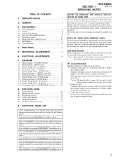
.... HCD-NEZ30 SECTION 1 Ver. 1.5 SERVICING NOTES NOTES ON HANDLING THE OPTICAL PICK-UP BLOCK OR BASE UNIT The laser diode in the optical pickup block. During repair, pay...of printed wiring board, schematic diagram and electrical parts list of original service manual/SUPPLEMENT-1 according to the solder joint for too long, so be added to... When repairing the set to ordinary solder. 3 TABLE OF CONTENTS 1. MAIN Section 18 7-3. CD Board 21 7-5. MAIN Section (2/2 24 7-8. AC Board 29 7-12. Mechanical Deck Section 37 8-3. Base Unit (BU-K8BD83S-WOD 9 3-5. CD SERVO Section...
.... HCD-NEZ30 SECTION 1 Ver. 1.5 SERVICING NOTES NOTES ON HANDLING THE OPTICAL PICK-UP BLOCK OR BASE UNIT The laser diode in the optical pickup block. During repair, pay...of printed wiring board, schematic diagram and electrical parts list of original service manual/SUPPLEMENT-1 according to the solder joint for too long, so be added to... When repairing the set to ordinary solder. 3 TABLE OF CONTENTS 1. MAIN Section 18 7-3. CD Board 21 7-5. MAIN Section (2/2 24 7-8. AC Board 29 7-12. Mechanical Deck Section 37 8-3. Base Unit (BU-K8BD83S-WOD 9 3-5. CD SERVO Section...
Service Manual
Page 20
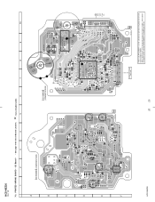
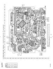
... - • See page 19 for Circuit Boards Location. : Uses unleaded solder. 1 2 3 4 5 6 7 8 9 10 A CD BOARD (COMPONENT SIDE) C401 B C R401 D C201 R201 E C202 C424 C101 C102 C108 C110 R207 R202 C203 R423 C406 R421 C272 C104 C109 C271 C105 C107 ...20 OPTICAL PICK-UP BLOCK KSM-213CDP 11 1-868-067- (11) Refer to SUPPLEMENT-1 for the CD board of printed wiring board of original service manual/SUPPLEMENT-1 according to either of UK and East European models. When repairing the set of except UK and East European models, refer to the set. HCD-NEZ30 Ver. 1.5 7-3.
... - • See page 19 for Circuit Boards Location. : Uses unleaded solder. 1 2 3 4 5 6 7 8 9 10 A CD BOARD (COMPONENT SIDE) C401 B C R401 D C201 R201 E C202 C424 C101 C102 C108 C110 R207 R202 C203 R423 C406 R421 C272 C104 C109 C271 C105 C107 ...20 OPTICAL PICK-UP BLOCK KSM-213CDP 11 1-868-067- (11) Refer to SUPPLEMENT-1 for the CD board of printed wiring board of original service manual/SUPPLEMENT-1 according to either of UK and East European models. When repairing the set of except UK and East European models, refer to the set. HCD-NEZ30 Ver. 1.5 7-3.
Service Manual
Page 21
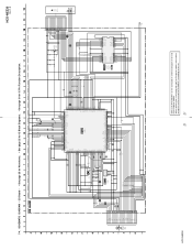
...POWVCC MUTE GND C405 0.1 SPSP+ SLSL+ C406 0.1 S201 (LIMIT) OPTICAL PICK-UP BLOCK KSM-213CDP M401 (SPINDLE) M402 (SLED) HCD-NEZ30 Refer to SUPPLEMENT-1 for IC Pin Function Description. HCD-NEZ30 Ver. 1.5 (Page 23) DATA CLK-MP3 M-MUTE DVDD(3.3V) D-OUT D-GND L-CH A-GND R-CH AVDD(3.3V) XTCN XRST ...• See page 25 for IC Block Diagrams. • See page 31 for the CD board of schematic diagram of original service manual/SUPPLEMENT-1 according to either of UK and East European models. When repairing the set of except UK and East European models, refer to the set. 21 21 7-4....
...POWVCC MUTE GND C405 0.1 SPSP+ SLSL+ C406 0.1 S201 (LIMIT) OPTICAL PICK-UP BLOCK KSM-213CDP M401 (SPINDLE) M402 (SLED) HCD-NEZ30 Refer to SUPPLEMENT-1 for IC Pin Function Description. HCD-NEZ30 Ver. 1.5 (Page 23) DATA CLK-MP3 M-MUTE DVDD(3.3V) D-OUT D-GND L-CH A-GND R-CH AVDD(3.3V) XTCN XRST ...• See page 25 for IC Block Diagrams. • See page 31 for the CD board of schematic diagram of original service manual/SUPPLEMENT-1 according to either of UK and East European models. When repairing the set of except UK and East European models, refer to the set. 21 21 7-4....
Service Manual
Page 22
...of printed wiring board of UK and East European models. Location Ref. HCD-NEZ30 When repairing the set of US and Canadian models, refer to either of original service manual/SUPPLEMENT-1 according to the set of except UK and East European models, ...refer to SUPPLEMENT-2 for Circuit Boards Location. : Uses unleaded solder. 1 2 3 4 5 6 7 8 9 10 11 12 13 14 15 MAIN BOARD A (Page 26) D PANEL BOARD (Page 20) A CD...
...of printed wiring board of UK and East European models. Location Ref. HCD-NEZ30 When repairing the set of US and Canadian models, refer to either of original service manual/SUPPLEMENT-1 according to the set of except UK and East European models, ...refer to SUPPLEMENT-2 for Circuit Boards Location. : Uses unleaded solder. 1 2 3 4 5 6 7 8 9 10 11 12 13 14 15 MAIN BOARD A (Page 26) D PANEL BOARD (Page 20) A CD...
Service Manual
Page 23
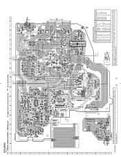
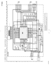
... 470p R505 47k R506 1k R385 1k R386 100 R391 R392 D324 UDZSTE-174.7B D320 MC2840-T112-1 R521 10k R517 47k D307 1SS355TE CD-R C238 22 50V CD-L C138 22 50V SCOR SENS XLAT MP3-ACK MP3-O-REQ MP3-XLAT MP3-DATA CLK MP3-I-REQ XRST XTACN C366 220p MP3-SSTB...-L SP-L SP-L HP-L HP-L HP-L CN500 13P (Page 24) (Page 24) HCD-NEZ30 23 23 Refer to SUPPLEMENT-1 for the MAIN board of schematic diagram of original service manual/SUPPLEMENT-1 according to either of except US and Canadian models. MAIN Section (1/2) - When repairing the set of US and Canadian models, refer to the set...
... 470p R505 47k R506 1k R385 1k R386 100 R391 R392 D324 UDZSTE-174.7B D320 MC2840-T112-1 R521 10k R517 47k D307 1SS355TE CD-R C238 22 50V CD-L C138 22 50V SCOR SENS XLAT MP3-ACK MP3-O-REQ MP3-XLAT MP3-DATA CLK MP3-I-REQ XRST XTACN C366 220p MP3-SSTB...-L SP-L SP-L HP-L HP-L HP-L CN500 13P (Page 24) (Page 24) HCD-NEZ30 23 23 Refer to SUPPLEMENT-1 for the MAIN board of schematic diagram of original service manual/SUPPLEMENT-1 according to either of except US and Canadian models. MAIN Section (1/2) - When repairing the set of US and Canadian models, refer to the set...
Service Manual
Page 24
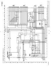
...-2 for the MAIN board of schematic diagram of original service manual/ SUPPLEMENT-2 according to the set of except UK and East European models, refer to either of except US and Canadian models. When repairing the set . When repairing the set . 24 HCD-NEZ30 Ver. 1.5 7-7. MAIN Section (2/2) - • See page...R122 470k JR215 0 INPUT SELECT, ELECTRICAL VOLUME IC302 BD3881FV BASS-R VEE OUT-R CONT BASS-L VDD OUT-L TRE-R AUX-L TRE-L AUX-R GND CD-L VOLI-R CD-R VOLI-L ST-L PBO-L ST-R PB0-R R211 22k C211 1000p RECO-R NF-R R138 2.2k R238 2.2k R214 4.7k R212 22k R114 4.7k...
...-2 for the MAIN board of schematic diagram of original service manual/ SUPPLEMENT-2 according to the set of except UK and East European models, refer to either of except US and Canadian models. When repairing the set . When repairing the set . 24 HCD-NEZ30 Ver. 1.5 7-7. MAIN Section (2/2) - • See page...R122 470k JR215 0 INPUT SELECT, ELECTRICAL VOLUME IC302 BD3881FV BASS-R VEE OUT-R CONT BASS-L VDD OUT-L TRE-R AUX-L TRE-L AUX-R GND CD-L VOLI-R CD-R VOLI-L ST-L PBO-L ST-R PB0-R R211 22k C211 1000p RECO-R NF-R R138 2.2k R238 2.2k R214 4.7k R212 22k R114 4.7k...
Service Manual
Page 26
...repairing... - PANEL Board - • See page 19 for the PANEL board of printed wiring board of original service manual/SUPPLEMENT-3 according to SUPPLEMENT-3 for Circuit Boards Location. : Uses unleaded solder. 1 2 3 4 5 6...R724 JR713 R824 R825 R826 LCD801 LIQUID CRYSTAL DISPLAY JW896 JW895 100 81 50 S820 CD LID C OPEN/CLOSE DETECT 17 1 CN804 2 1 (EXCEPT US, CND) ... Q802 G-5 Q803 H-5 Q804 G-5 Q805 G-5 Q807 B-8 Q808 C-4 HCD-NEZ30 7-8. TAPE MECHANISM DECK BLOCK SUPPLIED WITH THE ASSEMBLED BLOCK 26 26 HCD-NEZ30 Ver. 1.5 • Semiconductor Location Ref.
...repairing... - PANEL Board - • See page 19 for the PANEL board of printed wiring board of original service manual/SUPPLEMENT-3 according to SUPPLEMENT-3 for Circuit Boards Location. : Uses unleaded solder. 1 2 3 4 5 6...R724 JR713 R824 R825 R826 LCD801 LIQUID CRYSTAL DISPLAY JW896 JW895 100 81 50 S820 CD LID C OPEN/CLOSE DETECT 17 1 CN804 2 1 (EXCEPT US, CND) ... Q802 G-5 Q803 H-5 Q804 G-5 Q805 G-5 Q807 B-8 Q808 C-4 HCD-NEZ30 7-8. TAPE MECHANISM DECK BLOCK SUPPLIED WITH THE ASSEMBLED BLOCK 26 26 HCD-NEZ30 Ver. 1.5 • Semiconductor Location Ref.
Service Manual
Page 27
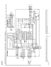
... POWER-ON I-PWR.MONI M-GND M+10V 1 TAPE MECHANISM DECK BLOCK SUPPLIED WITH THE ASSEMBLED BLOCK 1 REC PACK MOTOR10V R849... 9 C812 470p R815 1k REMOTE CONTROL RECEIVER R805 0 R863 100 R841 1k D806 ... 1 GND 2 FFC804 (Page 24) (NC) S820 CD LID OPEN/CLOSE DETECT HCD-NEZ30 Refer to SUPPLEMENT-3 for IC Pin Function Description. S807 ...R883 4.7k S811 S812 TUNING - SCHEMATIC DIAGRAM - When repairing the set of except UK and East European models, refer ...31 for the PANEL board of schematic diagram of original service manual/SUPPLEMENT-3 according to either of UK and East European models...
... POWER-ON I-PWR.MONI M-GND M+10V 1 TAPE MECHANISM DECK BLOCK SUPPLIED WITH THE ASSEMBLED BLOCK 1 REC PACK MOTOR10V R849... 9 C812 470p R815 1k REMOTE CONTROL RECEIVER R805 0 R863 100 R841 1k D806 ... 1 GND 2 FFC804 (Page 24) (NC) S820 CD LID OPEN/CLOSE DETECT HCD-NEZ30 Refer to SUPPLEMENT-3 for IC Pin Function Description. S807 ...R883 4.7k S811 S812 TUNING - SCHEMATIC DIAGRAM - When repairing the set of except UK and East European models, refer ...31 for the PANEL board of schematic diagram of original service manual/SUPPLEMENT-3 according to either of UK and East European models...
Service Manual
Page 42
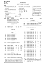
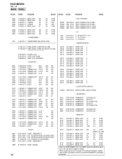
... The components identified by reference number, please include the board. Replace only with mark 0 are critical for the CD board of electrical parts list of original service manual/SUPPLEMENT...-1 42 according to the set . Les composants identifiés par une marque 0 sont critiquens pour la sécurité. When repairing... 10uF 20% 1000uF 20% 0.0047uF 20% Remark 50V 16V 250V Ref. No. HCD-NEZ30 Ver. 1.5 AC CD SECTION 9 ELECTRICAL PARTS LIST NOTE: • Due to standardization, replacements in the ...
... The components identified by reference number, please include the board. Replace only with mark 0 are critical for the CD board of electrical parts list of original service manual/SUPPLEMENT...-1 42 according to the set . Les composants identifiés par une marque 0 sont critiquens pour la sécurité. When repairing... 10uF 20% 1000uF 20% 0.0047uF 20% Remark 50V 16V 250V Ref. No. HCD-NEZ30 Ver. 1.5 AC CD SECTION 9 ELECTRICAL PARTS LIST NOTE: • Due to standardization, replacements in the ...
Service Manual
Page 44
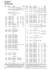
... 7P CN903 1-819-132-11 PIN, CONNECTOR 4P Ref. R902 R911 R911 R912 Part No. Part No. When repairing the set of except UK and East European models, refer to the set. No. HCD-NEZ30 Ver. 1.5 DC HEAD PHONE Ref. Description Remark 1-216-837-11 1-216-829-11 1-216-841-11 1-216-841... 10K 5% 1/10W R548 1-216-833-11 METAL CHIP 10K 5% 1/10W Refer to SUPPLEMENT-2 for the HEAD PHONE board of electrical parts list of original service manual/SUPPLEMENT-2 according to either of UK and East European models.
... 7P CN903 1-819-132-11 PIN, CONNECTOR 4P Ref. R902 R911 R911 R912 Part No. Part No. When repairing the set of except UK and East European models, refer to the set. No. HCD-NEZ30 Ver. 1.5 DC HEAD PHONE Ref. Description Remark 1-216-837-11 1-216-829-11 1-216-841-11 1-216-841... 10K 5% 1/10W R548 1-216-833-11 METAL CHIP 10K 5% 1/10W Refer to SUPPLEMENT-2 for the HEAD PHONE board of electrical parts list of original service manual/SUPPLEMENT-2 according to either of UK and East European models.
Service Manual
Page 45
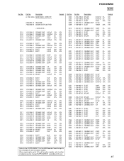
When repairing the set . HCD-NEZ30 MAIN Ref. Description A-1158-128-A MAIN BOARD, COMPLETE Remark 2-586-961-01 HEAT SINK 7-685-646-01 SCREW +BVTP 3X8 TYPE1 < CAPACITOR > C101 1-162-964-... 20% 50V 10% 50V 10% 50V 0.5PF 50V 20% 16V Refer to the SUPPLEMENT-1 for the MAIN board of electrical parts list of original service manual/SUPPLEMENT-1 according to the set of US and Canadian models, refer to either of except US and Canadian models. Ref. Description 1-130-479-00 1-130...
When repairing the set . HCD-NEZ30 MAIN Ref. Description A-1158-128-A MAIN BOARD, COMPLETE Remark 2-586-961-01 HEAT SINK 7-685-646-01 SCREW +BVTP 3X8 TYPE1 < CAPACITOR > C101 1-162-964-... 20% 50V 10% 50V 10% 50V 0.5PF 50V 20% 16V Refer to the SUPPLEMENT-1 for the MAIN board of electrical parts list of original service manual/SUPPLEMENT-1 according to the set of US and Canadian models, refer to either of except US and Canadian models. Ref. Description 1-130-479-00 1-130...
Service Manual
Page 48
Part No. When repairing the set of except UK and East European models, refer to either of original service manual/SUPPLEMENT-3 according to SUPPLEMENT-3 for the PANEL board of electrical parts list of UK and East European models. Part No. No. Description Remark R523 1-216-..., CND) 5% 1/10W 5% 1/10W 5% 1/10W 5% 1/10W R713 1-216-821-11 METAL CHIP 1K R715 1-216-809-11 METAL CHIP 100 5% 1/10W 5% 1/10W Refer to the set. HCD-NEZ30 Ver. 1.5 MAIN PANEL Ref. No. Description Remark Ref.
Part No. When repairing the set of except UK and East European models, refer to either of original service manual/SUPPLEMENT-3 according to SUPPLEMENT-3 for the PANEL board of electrical parts list of UK and East European models. Part No. No. Description Remark R523 1-216-..., CND) 5% 1/10W 5% 1/10W 5% 1/10W 5% 1/10W R713 1-216-821-11 METAL CHIP 1K R715 1-216-809-11 METAL CHIP 100 5% 1/10W 5% 1/10W Refer to the set. HCD-NEZ30 Ver. 1.5 MAIN PANEL Ref. No. Description Remark Ref.


