
Operating Instructions
Page 1
...is 8. • Compatibility with an adaptor). To tune in , and then "TUNED" and "STEREO" (for the customers in stop , press TUNING MODE repeatedly until "MONO" appears to... optical instruments with the SonicStage software. Model No Serial No CMT-HPR90 © 2006 Sony Corporation Printed in Power Saving Mode, the following are displayed when performing...-124-11(1) Micro HI-FI Component System Operating Instructions GB Owner's Record The model and serial numbers are used in the desired station. Reorient or relocate the receiving antenna. - Note on DualDiscs...
...is 8. • Compatibility with an adaptor). To tune in , and then "TUNED" and "STEREO" (for the customers in stop , press TUNING MODE repeatedly until "MONO" appears to... optical instruments with the SonicStage software. Model No Serial No CMT-HPR90 © 2006 Sony Corporation Printed in Power Saving Mode, the following are displayed when performing...-124-11(1) Micro HI-FI Component System Operating Instructions GB Owner's Record The model and serial numbers are used in the desired station. Reorient or relocate the receiving antenna. - Note on DualDiscs...

Operating Instructions
Page 2
...TV. Use buttons on the remote to control the Play Timer. Sleep Timer: You can be received. • Connect the antenna properly. • Find a location and an orientation that are unbalanced... repeatedly until both channels driven, from sources of 47 kilohms Outputs PHONES (stereo mini jack): accepts headphones with the Sleep Timer, the Sleep Timer has priority. On safety...stable stand). • Move the speakers away from the system, or place them in Power Saving Mode. Tip You can preset your nearest Sony dealer. Press SLEEP on the remote repeatedly....
...TV. Use buttons on the remote to control the Play Timer. Sleep Timer: You can be received. • Connect the antenna properly. • Find a location and an orientation that are unbalanced... repeatedly until both channels driven, from sources of 47 kilohms Outputs PHONES (stereo mini jack): accepts headphones with the Sleep Timer, the Sleep Timer has priority. On safety...stable stand). • Move the speakers away from the system, or place them in Power Saving Mode. Tip You can preset your nearest Sony dealer. Press SLEEP on the remote repeatedly....

Service Manual
Page 1
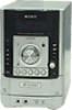
...70 W (4 ohms at 1 kHz, 10% THD) Inputs AUDIO IN: Sensitivity 250 mV, impedance of 47 kilohms Outputs PHONES (stereo mini jack): accepts headphones with an impedance of 8 ohms or more than 44.6 µW * This output is the amplifier, CD...HCD-HPR90 • HCD-HPR90 is the amplifier, CD player and tuner section in CMT-HPR99XM. COMPACT DISC RECEIVER 9-887-115-03 2007A05-1 © 2007.01 Sony Corporation Personal Audio Division Published by Sony Techno Create Corporation rated 85 watts per channel minimum RMS power, with no more SPEAKER: accepts impedance of 4 ohms CD player section System...
...70 W (4 ohms at 1 kHz, 10% THD) Inputs AUDIO IN: Sensitivity 250 mV, impedance of 47 kilohms Outputs PHONES (stereo mini jack): accepts headphones with an impedance of 8 ohms or more than 44.6 µW * This output is the amplifier, CD...HCD-HPR90 • HCD-HPR90 is the amplifier, CD player and tuner section in CMT-HPR99XM. COMPACT DISC RECEIVER 9-887-115-03 2007A05-1 © 2007.01 Sony Corporation Personal Audio Division Published by Sony Techno Create Corporation rated 85 watts per channel minimum RMS power, with no more SPEAKER: accepts impedance of 4 ohms CD player section System...
Service Manual
Page 5
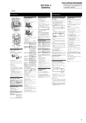
...are recorded onto the disc. • The system can wake up to select a disc. 4 Press / repeatedly or turn off stereo reception. Tip The Play Timer setting remains as... • The following functions are displayed; - to select the desired preset number. SECTION 2 GENERAL HCD-HPR90/HPR99XM This section is stopped. on the remote (or turn the jog dial on the unit and...TUNING MODE repeatedly until you can select normal play ) wj . To connect an optional component Connect additional audio component to the AUDIO IN jack on an MP3 disc Select a track or file Find...
...are recorded onto the disc. • The system can wake up to select a disc. 4 Press / repeatedly or turn off stereo reception. Tip The Play Timer setting remains as... • The following functions are displayed; - to select the desired preset number. SECTION 2 GENERAL HCD-HPR90/HPR99XM This section is stopped. on the remote (or turn the jog dial on the unit and...TUNING MODE repeatedly until you can select normal play ) wj . To connect an optional component Connect additional audio component to the AUDIO IN jack on an MP3 disc Select a track or file Find...

Service Manual
Page 6
...antenna. Prepare the sound source, and then press VOLUME +/- HCD-HPR90/HPR99XM - on for reference NOTE: The XM Radio ID does... stations and tune them in , and then "TUNED" and "STEREO" (for how to install and how to see the instructions at... ) . +/- (select folder) . Power Saving Mode2) The display is off to receive XM service (sold separately. Preset number 3 Press +/- Press TUNER/BAND repeatedly. 2 ... activation fee may need a major credit card. To select CD Tuner Component (connected using the system, connect the XM Connect-and-Play antenna to the XM satellite Radio...
...antenna. Prepare the sound source, and then press VOLUME +/- HCD-HPR90/HPR99XM - on for reference NOTE: The XM Radio ID does... stations and tune them in , and then "TUNED" and "STEREO" (for how to install and how to see the instructions at... ) . +/- (select folder) . Power Saving Mode2) The display is off to receive XM service (sold separately. Preset number 3 Press +/- Press TUNER/BAND repeatedly. 2 ... activation fee may need a major credit card. To select CD Tuner Component (connected using the system, connect the XM Connect-and-Play antenna to the XM satellite Radio...
Service Manual
Page 16
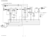
...J981 AUDIO IN R-CH (HPR99XM) J001 XM D+ 3 D- 2 VCC 1 XM RECEIVER IC001 18 COMM_RX_P 19 COMM_RX_N 23 COMM_TX_P 22 COMM_TX_N I2S_DA 37 I2S_CLK 39 I2S_LRCLK 41 I2S_OCLK... ELECTRICAL VOLUME, SURROUND/TONE CONTROL IC1501 A1 7 B1 5 C1 9 SEL1 4 VIN1 1 OUT1 17 14 13 (HPR90) MUTING IC1503 R-CH MUTING CONTROL SWITCH Q1501, 1502 HEADPHONE AMP IC1502 MUTING IC1504 R-CH R-CH MUTING CONTROL SWITCH Q1508...STEREO ST DIN ST CLK ST CE 56 ST DIN/STEREO 54 ST DOUT 55 ST CLK 53 ST CE FM ANT L-OUT R-OUT AM ANT TUNER (FM/AM) R-CH SYSTEM CONTROLLER IC1301 (2/4) HCD-HPR90/HPR99XM 16 16 HCD-HPR90/...
...J981 AUDIO IN R-CH (HPR99XM) J001 XM D+ 3 D- 2 VCC 1 XM RECEIVER IC001 18 COMM_RX_P 19 COMM_RX_N 23 COMM_TX_P 22 COMM_TX_N I2S_DA 37 I2S_CLK 39 I2S_LRCLK 41 I2S_OCLK... ELECTRICAL VOLUME, SURROUND/TONE CONTROL IC1501 A1 7 B1 5 C1 9 SEL1 4 VIN1 1 OUT1 17 14 13 (HPR90) MUTING IC1503 R-CH MUTING CONTROL SWITCH Q1501, 1502 HEADPHONE AMP IC1502 MUTING IC1504 R-CH R-CH MUTING CONTROL SWITCH Q1508...STEREO ST DIN ST CLK ST CE 56 ST DIN/STEREO 54 ST DOUT 55 ST CLK 53 ST CE FM ANT L-OUT R-OUT AM ANT TUNER (FM/AM) R-CH SYSTEM CONTROLLER IC1301 (2/4) HCD-HPR90/HPR99XM 16 16 HCD-HPR90/...

Service Manual
Page 23
...1000 6.3V C1401 0.1 R1306 100 R1307 100 C1310 22p SYSTEM CONTROLLER IC1301 M30622MEP-A39FPU0(HPR90) M30624MGP-A58FPU0(HPR99XM) R1320 47k R1319 100 R1417 10k R1316 0 C1316 0.1 R1313 0 R1311 220k R1309 10k (HPR90) X1301 32.768KHz R1418 0 C1311 22p X1302 5MHz ...VSS AMP SC VCC AMP SI LINE MUTE SEL B HP MUTE POWER ON/OFF ST DIN/STEREO ST CLK ST DOUT ST CE ST TUNED SEL A R1423 10k R1424 10k R1425 10k R1426...A1 A3 A5 A6 A4 (Page 24) A7 EP1202 (CHASSIS) (Page 25) C7 C5 C6 C9 C8 HCD-HPR90/HPR99XM 23 23 MAIN Section (1/3) - • See page 36 for Waveforms. • See page 37 ...
...1000 6.3V C1401 0.1 R1306 100 R1307 100 C1310 22p SYSTEM CONTROLLER IC1301 M30622MEP-A39FPU0(HPR90) M30624MGP-A58FPU0(HPR99XM) R1320 47k R1319 100 R1417 10k R1316 0 C1316 0.1 R1313 0 R1311 220k R1309 10k (HPR90) X1301 32.768KHz R1418 0 C1311 22p X1302 5MHz ...VSS AMP SC VCC AMP SI LINE MUTE SEL B HP MUTE POWER ON/OFF ST DIN/STEREO ST CLK ST DOUT ST CE ST TUNED SEL A R1423 10k R1424 10k R1425 10k R1426...A1 A3 A5 A6 A4 (Page 24) A7 EP1202 (CHASSIS) (Page 25) C7 C5 C6 C9 C8 HCD-HPR90/HPR99XM 23 23 MAIN Section (1/3) - • See page 36 for Waveforms. • See page 37 ...

Service Manual
Page 24
...C1213 0.01 C1 C1526 1 50V JR1501 0 R1523 100k C1507 100 16V R1514 2.2k R1513 R1516 2.2k 10k C1506 0.1 R1511 10k R1512 10k (HPR90) B A X3 X0 X X1 X2 VCC Y0 C1576 1 50V C2 JR1502 0 R1573 100k (HPR99XM) Y2 Y Y3 Y1 INH VEE GND ...INVERTER Q1505 RT1N141C INVERTER FM75Ω COAXIAL ANTENNA AM TUNER (FM/AM) SUPPLIED WITH THE ASSEMBLED BLOCK (Page 25) DO/STEREO ST CLK ST DIN ST CE NC AGND R OUT +9V L OUT CN1310 9P B1 B2 B3 B4 B5 56 55...7k C1212 470 10V +7V REGULATOR IC1205 TA7807S OG I R1557 C1567 R1555 47 220 10V 22k HCD-HPR90/HPR99XM 24 24 SCHEMATIC DIAGRAM...
...C1213 0.01 C1 C1526 1 50V JR1501 0 R1523 100k C1507 100 16V R1514 2.2k R1513 R1516 2.2k 10k C1506 0.1 R1511 10k R1512 10k (HPR90) B A X3 X0 X X1 X2 VCC Y0 C1576 1 50V C2 JR1502 0 R1573 100k (HPR99XM) Y2 Y Y3 Y1 INH VEE GND ...INVERTER Q1505 RT1N141C INVERTER FM75Ω COAXIAL ANTENNA AM TUNER (FM/AM) SUPPLIED WITH THE ASSEMBLED BLOCK (Page 25) DO/STEREO ST CLK ST DIN ST CE NC AGND R OUT +9V L OUT CN1310 9P B1 B2 B3 B4 B5 56 55...7k C1212 470 10V +7V REGULATOR IC1205 TA7807S OG I R1557 C1567 R1555 47 220 10V 22k HCD-HPR90/HPR99XM 24 24 SCHEMATIC DIAGRAM...
Service Manual
Page 48
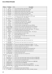
... transfer clock signal output to the tuner (FM/AM) Serial data and stereo detection signal input from the tuner (FM/AM) Sub power on/off...the stream processor Soft muting control signal output to the stream processor System reset signal output to the digital power amplifier "L": reset Shut down...receiver (HPR99XM) Serial data input from the EEPROM Serial data transfer clock signal input from the EEPROM LED drive signal output terminal for STANDBY indicator "H": LED on Not used Front panel key input terminal (A/D input) Jog dial pulse input from the rotary encoder (VOLUME) (A/D input) 48 HCD-HPR90...
... transfer clock signal output to the tuner (FM/AM) Serial data and stereo detection signal input from the tuner (FM/AM) Sub power on/off...the stream processor Soft muting control signal output to the stream processor System reset signal output to the digital power amplifier "L": reset Shut down...receiver (HPR99XM) Serial data input from the EEPROM Serial data transfer clock signal input from the EEPROM LED drive signal output terminal for STANDBY indicator "H": LED on Not used Front panel key input terminal (A/D input) Jog dial pulse input from the rotary encoder (VOLUME) (A/D input) 48 HCD-HPR90...

Service Manual
Page 72
... C1312 0.1 C1301 1000 6.3V C1401 0.1 R1306 100 R1307 100 C1310 22p SYSTEM CONTROLLER IC1301 M30622MEP-B10FPU0(HPR90) M30624MGP-A60FPU0(HPR99XM) R1320 47k R1319 100 R1417 10k R1316 0 C1316 0.1 R1313 0 R1311 220k R1309 10k (HPR90) X1301 32.768KHz R1418 0 C1311 22p X1302 5MHz R1421 0 R1318 100 ... MUTE SEL INH VSS AMP SC VCC AMP SI LINE MUTE SEL B HP MUTE POWER ON/OFF ST DIN/STEREO ST CLK ST DOUT ST CE ST TUNED SEL A R1423 10k R1424 10k R1425 10k R1426 10k R1427 10k ... A5 A6 A4 (Page 5) A7 EP1202 (CHASSIS) C7 C5 C6 C9 C8 (Page 6) HCD-HPR90/HPR99XM 4 4 HCD-HPR90/HPR99XM 2-2.
... C1312 0.1 C1301 1000 6.3V C1401 0.1 R1306 100 R1307 100 C1310 22p SYSTEM CONTROLLER IC1301 M30622MEP-B10FPU0(HPR90) M30624MGP-A60FPU0(HPR99XM) R1320 47k R1319 100 R1417 10k R1316 0 C1316 0.1 R1313 0 R1311 220k R1309 10k (HPR90) X1301 32.768KHz R1418 0 C1311 22p X1302 5MHz R1421 0 R1318 100 ... MUTE SEL INH VSS AMP SC VCC AMP SI LINE MUTE SEL B HP MUTE POWER ON/OFF ST DIN/STEREO ST CLK ST DOUT ST CE ST TUNED SEL A R1423 10k R1424 10k R1425 10k R1426 10k R1427 10k ... A5 A6 A4 (Page 5) A7 EP1202 (CHASSIS) C7 C5 C6 C9 C8 (Page 6) HCD-HPR90/HPR99XM 4 4 HCD-HPR90/HPR99XM 2-2.

Service Manual
Page 73
... MAIN Section (2/3) - • See page 37 for IC Block Diagrams. HCD-HPR90/HPR99XM FM75Ω COAXIAL ANTENNA AM HCD-HPR90/HPR99XM (2/3) TO XM REG BOARD (Refer to page 24 on original service ... 1 50V JR1501 0 R1523 100k C1507 100 16V R1514 2.2k R1513 R1516 2.2k 10k C1506 0.1 R1511 10k R1512 10k (HPR90) B A X3 X0 X X1 X2 VCC Y0 C1576 1 50V C2 JR1502 0 R1573 100k (HPR99XM) Y2 Y Y3...RT1N141C INVERTER Q1504 RT1N141C INVERTER Q1505 RT1N141C INVERTER TUNER (FM/AM) SUPPLIED WITH THE ASSEMBLED BLOCK DO/STEREO ST CLK ST DIN ST CE NC AGND R OUT +9V L OUT CN1310 9P B1 B2 B3...
... MAIN Section (2/3) - • See page 37 for IC Block Diagrams. HCD-HPR90/HPR99XM FM75Ω COAXIAL ANTENNA AM HCD-HPR90/HPR99XM (2/3) TO XM REG BOARD (Refer to page 24 on original service ... 1 50V JR1501 0 R1523 100k C1507 100 16V R1514 2.2k R1513 R1516 2.2k 10k C1506 0.1 R1511 10k R1512 10k (HPR90) B A X3 X0 X X1 X2 VCC Y0 C1576 1 50V C2 JR1502 0 R1573 100k (HPR99XM) Y2 Y Y3...RT1N141C INVERTER Q1504 RT1N141C INVERTER Q1505 RT1N141C INVERTER TUNER (FM/AM) SUPPLIED WITH THE ASSEMBLED BLOCK DO/STEREO ST CLK ST DIN ST CE NC AGND R OUT +9V L OUT CN1310 9P B1 B2 B3...


