
Operating Instructions
Page 6
... a Player in an Editing System Features 9 (GB) DVCAM Format 9 (GB) Other Features 11 (GB) Location and Function of Parts 12 (GB) Front Panel 12 (GB) Rear Panel 20 (GB) Supplied Remote Commander 25 (GB) Displaying Various Data 27 (GB) Notes on Video Cassettes 30 (GB) Inserting/Ejecting Cassettes 31 (GB) Notes on Playback/Recording 32 (GB) Playback 33 (GB) Connections for Playback 33 (GB) Settings for Playback 35 (GB) Playback Procedures 35 (GB) Playback Functions 36...
... a Player in an Editing System Features 9 (GB) DVCAM Format 9 (GB) Other Features 11 (GB) Location and Function of Parts 12 (GB) Front Panel 12 (GB) Rear Panel 20 (GB) Supplied Remote Commander 25 (GB) Displaying Various Data 27 (GB) Notes on Video Cassettes 30 (GB) Inserting/Ejecting Cassettes 31 (GB) Notes on Playback/Recording 32 (GB) Playback 33 (GB) Connections for Playback 33 (GB) Settings for Playback 35 (GB) Playback Procedures 35 (GB) Playback Functions 36...
Operating Instructions
Page 10
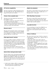
... output of digital video/audio signals in jog mode. Choice of interface connectors. • Analog video: component video, composite video, S- Internal time code generator/reader The unit contains a time code generator/reader that can all be monitored at playback speeds up to 14 times normal speed (DSR45) or up to 17 times normal speed (DSR-45P) in both standard-size and mini-size DVCAM/DV cassettes. • According to view color pictures at various playback...
... output of digital video/audio signals in jog mode. Choice of interface connectors. • Analog video: component video, composite video, S- Internal time code generator/reader The unit contains a time code generator/reader that can all be monitored at playback speeds up to 14 times normal speed (DSR45) or up to 17 times normal speed (DSR-45P) in both standard-size and mini-size DVCAM/DV cassettes. • According to view color pictures at various playback...

Operating Instructions
Page 19
... button Press this unit plays back a part of the tape where the recording format has been changed between PAL and NTSC, the displayed value may not advance correctly from that portion. - Even if the unit is in the DVCAM format. For details on the VTR SET menu, see "Recording Functions" on a ±12-hour cycle. You cannot make the counter operate on page 90 (GB). 5 Remote control detector 6 Time counter display Displays time data...
... button Press this unit plays back a part of the tape where the recording format has been changed between PAL and NTSC, the displayed value may not advance correctly from that portion. - Even if the unit is in the DVCAM format. For details on the VTR SET menu, see "Recording Functions" on a ±12-hour cycle. You cannot make the counter operate on page 90 (GB). 5 Remote control detector 6 Time counter display Displays time data...
Operating Instructions
Page 20
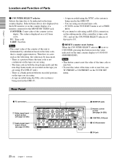
... display to 0:00:00:00 (0H00M00S00F). TC: Time code U-BIT: User bits Notes • The count value of the counter of this button resets the value indicated on the TC/UB SET menu is not continuous on the tape you are using the PAL color system is , simple approximation. A tape recorded using . - Rear Panel 1 TC connectors 1 Video signal input/ output section (see page 22 (GB)) 2 Audio signal input/ output section (see page 23 (GB)) 5 MONITOR jacks 3 Remote control...
... display to 0:00:00:00 (0H00M00S00F). TC: Time code U-BIT: User bits Notes • The count value of the counter of this button resets the value indicated on the TC/UB SET menu is not continuous on the tape you are using the PAL color system is , simple approximation. A tape recorded using . - Rear Panel 1 TC connectors 1 Video signal input/ output section (see page 22 (GB)) 2 Audio signal input/ output section (see page 23 (GB)) 5 MONITOR jacks 3 Remote control...
Operating Instructions
Page 21
... operating state as a time code generator or a VCR. Recording: Either the time code generated by means of digital signal processing. For details, see "Displaying Various Data" on the OTHERS menu to CONTROL S. • If the REMOTE/LOCAL switch is set to the Remote Control Unit (DSRM-20, not supplied) for monitoring. If you intend to disconnect or reconnect the DV cable, turn the unit off the device and pull out the plug of its power cord...
... operating state as a time code generator or a VCR. Recording: Either the time code generated by means of digital signal processing. For details, see "Displaying Various Data" on the OTHERS menu to CONTROL S. • If the REMOTE/LOCAL switch is set to the Remote Control Unit (DSRM-20, not supplied) for monitoring. If you intend to disconnect or reconnect the DV cable, turn the unit off the device and pull out the plug of its power cord...
Operating Instructions
Page 22
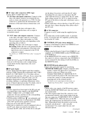
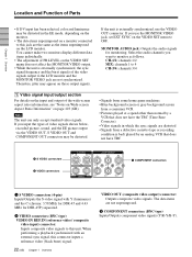
...-type) Inputs/Outputs component video signals (Y/R-Y/B-Y). Select the audio channels you use the VIDEO OUT connector. You cannot make two monitors display different data items individually. • The adjustment of PB LEVEL on those output signals. Chapter 1 Overview Location and Function of Parts • If DV input has been selected, color and luminance may be distorted. • Signals from some home game machines • Blue background screen or gray background screen from a consumer VCR • Pictures played at...
...-type) Inputs/Outputs component video signals (Y/R-Y/B-Y). Select the audio channels you use the VIDEO OUT connector. You cannot make two monitors display different data items individually. • The adjustment of PB LEVEL on those output signals. Chapter 1 Overview Location and Function of Parts • If DV input has been selected, color and luminance may be distorted. • Signals from some home game machines • Blue background screen or gray background screen from a consumer VCR • Pictures played at...

Operating Instructions
Page 27
... tape has been rewound to DATA. To display various data items on the menu, see "Searching using the Remote Commander or the DSRM-20 (not supplied). For details on the LCD monitor, set the CHARACTER DISPLAY (MONITOR OUT) switch to the MONITOR VIDEO jack. qa qs 1 Cassette memory indicator This item is negative, "-" appears as time code or remaining tape time, on the cassette memory, the indicator flashes. 2 Tape transport mode indicator Displays the tape transport mode. 3 Time counter (time code/user...
... tape has been rewound to DATA. To display various data items on the menu, see "Searching using the Remote Commander or the DSRM-20 (not supplied). For details on the LCD monitor, set the CHARACTER DISPLAY (MONITOR OUT) switch to the MONITOR VIDEO jack. qa qs 1 Cassette memory indicator This item is negative, "-" appears as time code or remaining tape time, on the cassette memory, the indicator flashes. 2 Tape transport mode indicator Displays the tape transport mode. 3 Time counter (time code/user...
Operating Instructions
Page 32
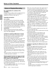
... signal has been input. Simple playback function for a tape recorded using a device connected to copy it onto other color system (i.e., PAL for the DSR-45, or NTSC for the DSR-45P), the image, sound and time code may be distorted for a while at the point where the recording format changes on the tape. • The tape transport control buttons may be disabled until the tape speed is that of the signals recorded on the tape played back. DSR-45P: PAL system). The tape transport control buttons...
... signal has been input. Simple playback function for a tape recorded using a device connected to copy it onto other color system (i.e., PAL for the DSR-45, or NTSC for the DSR-45P), the image, sound and time code may be distorted for a while at the point where the recording format changes on the tape. • The tape transport control buttons may be disabled until the tape speed is that of the signals recorded on the tape played back. DSR-45P: PAL system). The tape transport control buttons...

Operating Instructions
Page 35
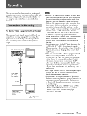
... recording format has been changed between the DVCAM format and the DV format, the picture and sound may be distorted. • The unit can play back only tapes recorded in the DVCAM format or in synchronization with the reference video (black burst) signal, set the monitor's input switch according to ON. Disconnect the cables. • Text data (time code, warnings, menus, etc.) are superimposed only on the VIDEO SET menu to the signals input. 2 Set up the recorder. Settings...
... recording format has been changed between the DVCAM format and the DV format, the picture and sound may be distorted. • The unit can play back only tapes recorded in the DVCAM format or in synchronization with the reference video (black burst) signal, set the monitor's input switch according to ON. Disconnect the cables. • Text data (time code, warnings, menus, etc.) are superimposed only on the VIDEO SET menu to the signals input. 2 Set up the recorder. Settings...
Operating Instructions
Page 41
... displayed on the VTR SET menu to make separate connections for input and output. If you are sent with a 6pin DV jack, when you do not need to OFF. - Set the INPUT SELECT selector to this unit. Connections for dubbing or as that has a 6-pin DV jack to a position where a signal is recorded in a different audio recording mode from the AC outlet beforehand. Monitor DSR-45/45P (rear panel) i.LINK cable (DV cable...
... displayed on the VTR SET menu to make separate connections for input and output. If you are sent with a 6pin DV jack, when you do not need to OFF. - Set the INPUT SELECT selector to this unit. Connections for dubbing or as that has a 6-pin DV jack to a position where a signal is recorded in a different audio recording mode from the AC outlet beforehand. Monitor DSR-45/45P (rear panel) i.LINK cable (DV cable...
Operating Instructions
Page 59
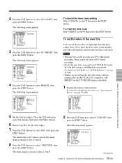
... V TC MAKE A TC RUN VTR TC FORMAT ETC JOG TC OUT Chapter 4 Setting the Time Code and Adjusting the Video Signals 5 Set the first two digits. The initial time code value is disabled. 1 Display the menu on the monitor. The following menu appears. The following menu appears. For details on TC/UB IN, see "Operating the Menus" on the TC/UB SET menu to select SET, then press the EXEC button. The menu display returns...
... V TC MAKE A TC RUN VTR TC FORMAT ETC JOG TC OUT Chapter 4 Setting the Time Code and Adjusting the Video Signals 5 Set the first two digits. The initial time code value is disabled. 1 Display the menu on the monitor. The following menu appears. The following menu appears. For details on TC/UB IN, see "Operating the Menus" on the TC/UB SET menu to select SET, then press the EXEC button. The menu display returns...
Operating Instructions
Page 61
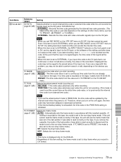
... unit power again, play back a tape, or set the INPUT SELECT selector to DV. • If the internal backup battery charge is exhausted, the time code of the FREE RUN setting will be recorded. • When this item is set to EXTERNAL, if you input time code to the DV jack that signal will be recorded when recording starts. AUTO: Automatically sets the mode in accordance with this problem, you may not be updated...
... unit power again, play back a tape, or set the INPUT SELECT selector to DV. • If the internal backup battery charge is exhausted, the time code of the FREE RUN setting will be recorded. • When this item is set to EXTERNAL, if you input time code to the DV jack that signal will be recorded when recording starts. AUTO: Automatically sets the mode in accordance with this problem, you may not be updated...

Operating Instructions
Page 72
... recording mode. t Clean the terminals on the LCD monitor and the MONITOR VIDEO output screen. The player rejects control. t If the cassette memory is displayed, check this unit). Moisture condensation has occurred in the DVCAM format. The player is not recorded in the player. Duplication (generating a work tape with cassette memory. STOP/ CAUTION No. 00 Warning Message RECORDER: [DV IN] NOT SELECTED 01 i.LINK CABLE: DISCONNECTED 02 i.LINK CABLE: MULTI CONNECTION 03 i.LINK CABLE: BUS RESET 10 PLAYER: RECORDING 11 PLAYER...
... recording mode. t Clean the terminals on the LCD monitor and the MONITOR VIDEO output screen. The player rejects control. t If the cassette memory is displayed, check this unit). Moisture condensation has occurred in the DVCAM format. The player is not recorded in the player. Duplication (generating a work tape with cassette memory. STOP/ CAUTION No. 00 Warning Message RECORDER: [DV IN] NOT SELECTED 01 i.LINK CABLE: DISCONNECTED 02 i.LINK CABLE: MULTI CONNECTION 03 i.LINK CABLE: BUS RESET 10 PLAYER: RECORDING 11 PLAYER...
Operating Instructions
Page 79
... : Records the time code generated by the internal clock when the power is set to the non-drop frame mode. If TC MAKE is set to PRESET, the mode is exhausted, the time code of the editing controller does not output a time code, if you use a tape with video and audio signals input via the DV jack. Even if this item is set to EXTERNAL, the INPUT SELECT selector on the TC/UB SET menu. PRESET: The time code starts...
... : Records the time code generated by the internal clock when the power is set to the non-drop frame mode. If TC MAKE is set to PRESET, the mode is exhausted, the time code of the editing controller does not output a time code, if you use a tape with video and audio signals input via the DV jack. Even if this item is set to EXTERNAL, the INPUT SELECT selector on the TC/UB SET menu. PRESET: The time code starts...

Operating Instructions
Page 85
..., or AUDIO DUB buttons separately when the unit is set to DV. • The color bars are delayed from the unit will also be recorded on the LCD monitor or MONITOR VIDEO output. • If you operate the unit to display the data codes on the VIDEO SET menu is set to the DV jack (See page 63 (GB)) EE sound of the input sound No button Mute screen is set the INPUT SELECT selector...
..., or AUDIO DUB buttons separately when the unit is set to DV. • The color bars are delayed from the unit will also be recorded on the LCD monitor or MONITOR VIDEO output. • If you operate the unit to display the data codes on the VIDEO SET menu is set to the DV jack (See page 63 (GB)) EE sound of the input sound No button Mute screen is set the INPUT SELECT selector...

Operating Instructions
Page 87
.../Menu V VIDEO SET Submenu (page) Setting PB LEVEL (page 68 (GB)) Adjusts the output video signal levels. (This is available only when the mode is playback, playback pause, slow playback, cue, or review.) SETUP: Switches the luminance signal setup level (0% or 7.5%). (This item is fixed to select. (The triangle under the bars are displayed in green when the settings are their center values. • The output video signals can be played at 7.5%. (You cannot play...
.../Menu V VIDEO SET Submenu (page) Setting PB LEVEL (page 68 (GB)) Adjusts the output video signal levels. (This is available only when the mode is playback, playback pause, slow playback, cue, or review.) SETUP: Switches the luminance signal setup level (0% or 7.5%). (This item is fixed to select. (The triangle under the bars are displayed in green when the settings are their center values. • The output video signals can be played at 7.5%. (You cannot play...

Operating Instructions
Page 90
...) Chapter 6 Adjusting and Setting Through Menus Set REC MODE to DV recording depending on both models. FRAME: Displays a frame image. Operating the Menus VTR SET menu Icon/Menu VTR VTR SET Submenu (page) REC MODE Setting Switches the recording mode between DVCAM and DV (SP mode only). When you intend to edit using an RS-422A connection, set to DVCAM, a tape with respect to DV SP. As a result, at maximum speed without displaying the picture.
...) Chapter 6 Adjusting and Setting Through Menus Set REC MODE to DV recording depending on both models. FRAME: Displays a frame image. Operating the Menus VTR SET menu Icon/Menu VTR VTR SET Submenu (page) REC MODE Setting Switches the recording mode between DVCAM and DV (SP mode only). When you intend to edit using an RS-422A connection, set to DVCAM, a tape with respect to DV SP. As a result, at maximum speed without displaying the picture.

Operating Instructions
Page 94
... the LCD monitor. On the Remote Control Unit, press the PLAY button while holding the REC button down. t Change the setting of the LCD monitor. The audio is noisy. • A damaged tape is interrupted. and the warning messages displayed on the OTHERS menu is set to WIRELESS and a Sony Remote Commander whose command mode is set to PB. t Set REC MODE to REC. Chapter 7 Maintenance Troubleshooting Symptom Cause/Remedy EE pictures and EE sound are not output...
... the LCD monitor. On the Remote Control Unit, press the PLAY button while holding the REC button down. t Change the setting of the LCD monitor. The audio is noisy. • A damaged tape is interrupted. and the warning messages displayed on the OTHERS menu is set to WIRELESS and a Sony Remote Commander whose command mode is set to PB. t Set REC MODE to REC. Chapter 7 Maintenance Troubleshooting Symptom Cause/Remedy EE pictures and EE sound are not output...

Operating Instructions
Page 96
... you use a PAL formatted tape in the DSR-45 (or use for playback. t Set the remote selector according to -10. • If the player is distorted. The CHARACTER DISPLAY (LCD) selector has been set the INPUT LEVEL selector to the lower step (+4 or -2) or turn the AUDIO REC LEVEL control knobs to that are using the time code. According to adjust the recording level. The unit does not function as to +4 or -2. 2 Set the AUDIO INPUT switch...
... you use a PAL formatted tape in the DSR-45 (or use for playback. t Set the remote selector according to -10. • If the player is distorted. The CHARACTER DISPLAY (LCD) selector has been set the INPUT LEVEL selector to the lower step (+4 or -2) or turn the AUDIO REC LEVEL control knobs to that are using the time code. According to adjust the recording level. The unit does not function as to +4 or -2. 2 Set the AUDIO INPUT switch...

Operating Instructions
Page 106
... scan the tape in the stop mode. EBU European Broadcasting Union. This is wrapped round the drum. Non-drop frame mode A mode of moisture on the head drum, the tape adheres to -Noise (ratio). PCM audio PCM stands for specific scenes, by viewing the video output or time code values while playing back the tape at the cassette entrance of Motion Picture and Television Engineers. Search mode A VCR operating mode used as 30. Servo lock...
... scan the tape in the stop mode. EBU European Broadcasting Union. This is wrapped round the drum. Non-drop frame mode A mode of moisture on the head drum, the tape adheres to -Noise (ratio). PCM audio PCM stands for specific scenes, by viewing the video output or time code values while playing back the tape at the cassette entrance of Motion Picture and Television Engineers. Search mode A VCR operating mode used as 30. Servo lock...

