Operating Instructions
Page 1
3-854-212-17 (1) 3CCD Color Video Camera Operating Instructions BRC-300/300P © 2004 Sony Corporation
3-854-212-17 (1) 3CCD Color Video Camera Operating Instructions BRC-300/300P © 2004 Sony Corporation

Operating Instructions
Page 3
... Feature ...40 Table of Parts ...15 Camera ...15 Remote Commander (supplied) ...17 RM-BR300 Remote Control Unit (not supplied) ...18 BRU-300/300P Optical Multiplex Unit (not supplied) ...BRC-300/300P Camera Using the Supplied Remote Commander ...10 Operating a BRC-300/300P Camera Using the RM-BR300 Remote Control Unit ...10 Operating Multiple BRC-300/300P Cameras Using the RM-BR300 Remote Control Unit ...11 Operating a BRC-300/300P Camera from a Long Distance ...12 Operating Multiple BRC-300/300P Cameras from a Long Distance ...13 Using BRC-300/300P Cameras and VISCA-controllable Cameras...
... Feature ...40 Table of Parts ...15 Camera ...15 Remote Commander (supplied) ...17 RM-BR300 Remote Control Unit (not supplied) ...18 BRU-300/300P Optical Multiplex Unit (not supplied) ...BRC-300/300P Camera Using the Supplied Remote Commander ...10 Operating a BRC-300/300P Camera Using the RM-BR300 Remote Control Unit ...10 Operating Multiple BRC-300/300P Cameras Using the RM-BR300 Remote Control Unit ...11 Operating a BRC-300/300P Camera from a Long Distance ...12 Operating Multiple BRC-300/300P Cameras from a Long Distance ...13 Using BRC-300/300P Cameras and VISCA-controllable Cameras...
Operating Instructions
Page 5
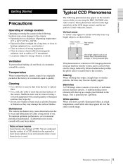
...period of the CCD image sensors, and do not block air circulation around the camera. You are using a soft cloth dampened with your Sony dealer. These phenomena stem from very bright subjects, as a single pixel blemish in... is used. Video monitor screen Pale vertical smear Getting Started Precautions Operating or storage location Operating or storing the camera in the following phenomena may appear on laser beams Laser beams may damage a CCD. Precautions / Typical CCD ... cautioned that the surface of a CCD should not be removed using the BRC-300/300P color video camera.
...period of the CCD image sensors, and do not block air circulation around the camera. You are using a soft cloth dampened with your Sony dealer. These phenomena stem from very bright subjects, as a single pixel blemish in... is used. Video monitor screen Pale vertical smear Getting Started Precautions Operating or storage location Operating or storing the camera in the following phenomena may appear on laser beams Laser beams may damage a CCD. Precautions / Typical CCD ... cautioned that the surface of a CCD should not be removed using the BRC-300/300P color video camera.
Operating Instructions
Page 10
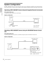
... the required components and the main usage of the Remote Control Unit System configuration Video monitor, VTR, etc. Operating a BRC-300/300P Camera Using the Supplied Remote Commander This system allows you : To perform pan/tilt and zoom operations comfortably using optional products. ... (supplied) Video signal Signal flow Operating a BRC-300/300P Camera Using the RM-BR300 Remote Control Unit This system allows you : To operate the camera readily from a short distance System configuration BRC-300/300P Video monitor, VTR, etc. BRC-300/300P RM-BR300 Remote Control Unit Video signal ...
... the required components and the main usage of the Remote Control Unit System configuration Video monitor, VTR, etc. Operating a BRC-300/300P Camera Using the Supplied Remote Commander This system allows you : To perform pan/tilt and zoom operations comfortably using optional products. ... (supplied) Video signal Signal flow Operating a BRC-300/300P Camera Using the RM-BR300 Remote Control Unit This system allows you : To operate the camera readily from a short distance System configuration BRC-300/300P Video monitor, VTR, etc. BRC-300/300P RM-BR300 Remote Control Unit Video signal ...

Operating Instructions
Page 11
Operating Multiple BRC-300/300P Cameras Using the RM-BR300 Remote Control Unit This system allows you: • To operate up to seven cameras remotely using a single Remote Control Unit • To perform pan/tilt and zoom operations comfortably using the joystick System configuration BRC-300/300P Video monitor, VTR, etc. Overview BRC-300/300P Video switcher BRC-300/300P RM-BR300 Remote Control Unit Video signal Remote control (VISCA) signal Tally/contact signal , Signal flow System Configuration 11
Operating Multiple BRC-300/300P Cameras Using the RM-BR300 Remote Control Unit This system allows you: • To operate up to seven cameras remotely using a single Remote Control Unit • To perform pan/tilt and zoom operations comfortably using the joystick System configuration BRC-300/300P Video monitor, VTR, etc. Overview BRC-300/300P Video switcher BRC-300/300P RM-BR300 Remote Control Unit Video signal Remote control (VISCA) signal Tally/contact signal , Signal flow System Configuration 11

Operating Instructions
Page 12
...VISCA RS-422 connector on the rear of the camera and the BOTTOM switches on the rear of the BRU-300/300P Optical Multiplex Unit instead. 12 System Configuration Overview BRC-300/300P CCFC-M100 Optical Fiber Cable BRU-300/300P Optical Multiplex Unit BRBK-303 Optical Multiplex ... RM-BR300 Remote Control Unit , Notes Signal flow • The BRC-300/300P camera does not operate if nothing is inserted into the camera. Use the connectors and switches on the bottom of the camera are disabled. Operating a BRC-300/300P Camera from a Long Distance This system allows you: • To operate...
...VISCA RS-422 connector on the rear of the camera and the BOTTOM switches on the rear of the BRU-300/300P Optical Multiplex Unit instead. 12 System Configuration Overview BRC-300/300P CCFC-M100 Optical Fiber Cable BRU-300/300P Optical Multiplex Unit BRBK-303 Optical Multiplex ... RM-BR300 Remote Control Unit , Notes Signal flow • The BRC-300/300P camera does not operate if nothing is inserted into the camera. Use the connectors and switches on the bottom of the camera are disabled. Operating a BRC-300/300P Camera from a Long Distance This system allows you: • To operate...

Operating Instructions
Page 13
... Control Unit Video signal Remote control (VISCA) signal Tally/contact signal , Signal flow System Configuration 13 Operating Multiple BRC-300/300P Cameras from a Long Distance This system allows you: • To operate up to seven cameras remotely from a distance up to 500 m (1,640 feet) • To perform pan/tilt and zoom operations comfortably using...
... Control Unit Video signal Remote control (VISCA) signal Tally/contact signal , Signal flow System Configuration 13 Operating Multiple BRC-300/300P Cameras from a Long Distance This system allows you: • To operate up to seven cameras remotely from a distance up to 500 m (1,640 feet) • To perform pan/tilt and zoom operations comfortably using...

Operating Instructions
Page 14
...single RM-BR300 Remote Control Unit • To perform pan/tilt and zoom operations comfortably using the joystick • To control the BRC-300/300P cameras remotely from a distance up to 500 m (1,640 feet) by transmitting the video signal and control signal using the Optical Fiber ...Cable Overview System configuration VISCA-controllable camera Video monitor, VTR, etc. VISCA-controllable camera BRC-300/300P BRU-300/ 300P CCFC-M100 Video switcher BRBK-303 BRC-300/300P CCFC-M100 Optical Fiber Cable BRBK-303 Optical Multiplex Card BRU-300/300P Optical Multiplex Unit RM-BR300 Remote ...
...single RM-BR300 Remote Control Unit • To perform pan/tilt and zoom operations comfortably using the joystick • To control the BRC-300/300P cameras remotely from a distance up to 500 m (1,640 feet) by transmitting the video signal and control signal using the Optical Fiber ...Cable Overview System configuration VISCA-controllable camera Video monitor, VTR, etc. VISCA-controllable camera BRC-300/300P BRU-300/ 300P CCFC-M100 Video switcher BRBK-303 BRC-300/300P CCFC-M100 Optical Fiber Cable BRBK-303 Optical Multiplex Card BRU-300/300P Optical Multiplex Unit RM-BR300 Remote ...
Operating Instructions
Page 18
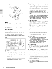
... of the brightness of the VALUE and BRIGHT controls" on page 39. G ONE PUSH AF button Press this button to focus on a far subject. B + L/R DIRECTION CAMERA AUTO FOCUS AUTO MANUAL POWER 1 2 3 4 5 6 7 NEAR FAR ONE PUSH AF qhqjqk ql w; D MODE button Press this control adjusts the R. When AUTO is... the VALUE and BRIGHT indicators are disabled. F AUTO/MANUAL button and AUTO indicator Press this button to the Operating Instructions supplied with BRC-300/ 300P cameras. R BRIGHT + PRESET MODE POSITION SHIFT 1 9 STD 2 10 REV 3 11 4 12 5 13 6 14 7 15 8 16 -
... of the brightness of the VALUE and BRIGHT controls" on page 39. G ONE PUSH AF button Press this button to focus on a far subject. B + L/R DIRECTION CAMERA AUTO FOCUS AUTO MANUAL POWER 1 2 3 4 5 6 7 NEAR FAR ONE PUSH AF qhqjqk ql w; D MODE button Press this control adjusts the R. When AUTO is... the VALUE and BRIGHT indicators are disabled. F AUTO/MANUAL button and AUTO indicator Press this button to the Operating Instructions supplied with BRC-300/ 300P cameras. R BRIGHT + PRESET MODE POSITION SHIFT 1 9 STD 2 10 REV 3 11 4 12 5 13 6 14 7 15 8 16 -
Operating Instructions
Page 20
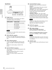
...Remote Control Unit is not effective. Otherwise, the setting is attached at the factory. Switch position 0 1 2 3 4 Note Camera mode Automatically selected (default) BRC-300/300P EVI-D70/D70P EVI-D100/D100P EVI-D30/D30P Y TALLY/CONTACT selector Select the function of Parts An RS-422 connector plug... is not effective. CONTACT: The contact output corresponding to the camera address selected with the Remote Control Unit is...
...Remote Control Unit is not effective. Otherwise, the setting is attached at the factory. Switch position 0 1 2 3 4 Note Camera mode Automatically selected (default) BRC-300/300P EVI-D70/D70P EVI-D100/D100P EVI-D30/D30P Y TALLY/CONTACT selector Select the function of Parts An RS-422 connector plug... is not effective. CONTACT: The contact output corresponding to the camera address selected with the Remote Control Unit is...
Operating Instructions
Page 22
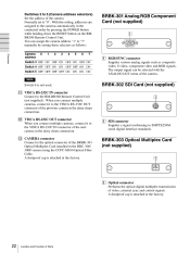
... BRBK-303 Optical Multiplex Card (not supplied) 1 A Optical connector Performs the optical digital multiplex transmission of Parts When you connect multiple cameras, connect it to the VISCA RS-232C OUT connector of the BRBK-303 Optical Multiplex Card installed in the daisy chain connection. With...the RMBR300 Remote Control Unit. Normally set to the VISCA RS-232C IN connector of the camera. Switches 3 to 5 (Camera address selectors) Set the address of the next camera in the BRC-300/ 300P camera using the CCFC-M100 Optical Fiber Cable. L VISCA RS-232C OUT connector When you ...
... BRBK-303 Optical Multiplex Card (not supplied) 1 A Optical connector Performs the optical digital multiplex transmission of Parts When you connect multiple cameras, connect it to the VISCA RS-232C OUT connector of the BRBK-303 Optical Multiplex Card installed in the daisy chain connection. With...the RMBR300 Remote Control Unit. Normally set to the VISCA RS-232C IN connector of the camera. Switches 3 to 5 (Camera address selectors) Set the address of the next camera in the BRC-300/ 300P camera using the CCFC-M100 Optical Fiber Cable. L VISCA RS-232C OUT connector When you ...
Operating Instructions
Page 40
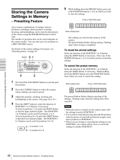
...settings in another POSITION. B + L/R DIRECTION To cancel the preset memory Select the function of the POSITION 1 to six positions on a BRC-300/300P camera. The POSITION 1 to 8 buttons can be stored in Memory - Flashing stops when the settings have stored the settings. 5 1 PANEL ... - The pressed button flashes during canceling of the POSITION buttons, 1 to 8, in one POSITION, you have been canceled. Press any of the settings. CAMERA AUTO FOCUS AUTO MANUAL POWER 1 2 3 4 5 6 7 NEAR FAR ONE PUSH AF Operation Using the RM-BR300 Remote Control Unit 4 2 1 ...
...settings in another POSITION. B + L/R DIRECTION To cancel the preset memory Select the function of the POSITION 1 to six positions on a BRC-300/300P camera. The POSITION 1 to 8 buttons can be stored in Memory - Flashing stops when the settings have stored the settings. 5 1 PANEL ... - The pressed button flashes during canceling of the POSITION buttons, 1 to 8, in one POSITION, you have been canceled. Press any of the settings. CAMERA AUTO FOCUS AUTO MANUAL POWER 1 2 3 4 5 6 7 NEAR FAR ONE PUSH AF Operation Using the RM-BR300 Remote Control Unit 4 2 1 ...
Operating Instructions
Page 49
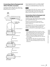
...SYNC IN VIDEO S VIDEO IN VISCA RS-232C OUT to Seventh BRC-300/300P Connections 49 Connecting a Device Equipped with VISCA RS-232C Connector Connections with the VISCA RS-232C cables (cross type) enable control of multiple cameras with VISCA RS-422 Connector Connection via the VISCA RS-422 ...; When the connections using the VISCA RS-422 connectors are connected simultaneously, the camera may malfunction. DC IN 12V EXT SYNC IN VIDEO S VIDEO IN VISCA RS-232C OUT to AC outlet Third to AC outlet Second BRC-300/300P VISCA RS-232C OUT RS-232C cable VISCA RS-232C IN 1 2...
...SYNC IN VIDEO S VIDEO IN VISCA RS-232C OUT to Seventh BRC-300/300P Connections 49 Connecting a Device Equipped with VISCA RS-232C Connector Connections with the VISCA RS-232C cables (cross type) enable control of multiple cameras with VISCA RS-422 Connector Connection via the VISCA RS-422 ...; When the connections using the VISCA RS-422 connectors are connected simultaneously, the camera may malfunction. DC IN 12V EXT SYNC IN VIDEO S VIDEO IN VISCA RS-232C OUT to AC outlet Third to AC outlet Second BRC-300/300P VISCA RS-232C OUT RS-232C cable VISCA RS-232C IN 1 2...
Operating Instructions
Page 50
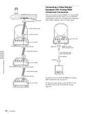
...301 Analog RGB Component Card, see page 42. DC IN 12V For details on how to Seventh BRC-300/300P To select the output signal, use the OUTPUT1 and OUTPUT2 items in the ANALOG OUT menu ... VISCA RS-422 cable to AC outlet Installation and Connections EXT SYNC IN VIDEO S VIDEO IN VISCA RS-232C OUT Second BRC-300/300P VISCA RS-422 VISCA RS-422 cable Video monitor, etc. DC IN 12V to RGB IN to VISCA RS-422 ...an optional BRBK-301 Analog RGB Component Card into the camera, you can output the signal from the camera by converting it into component video, RGB, composite video or S-video signal.
...301 Analog RGB Component Card, see page 42. DC IN 12V For details on how to Seventh BRC-300/300P To select the output signal, use the OUTPUT1 and OUTPUT2 items in the ANALOG OUT menu ... VISCA RS-422 cable to AC outlet Installation and Connections EXT SYNC IN VIDEO S VIDEO IN VISCA RS-232C OUT Second BRC-300/300P VISCA RS-422 VISCA RS-422 cable Video monitor, etc. DC IN 12V to RGB IN to VISCA RS-422 ...an optional BRBK-301 Analog RGB Component Card into the camera, you can output the signal from the camera by converting it into component video, RGB, composite video or S-video signal.
Operating Instructions
Page 52
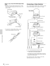
...S VIDEO IN VISCA RS-232C OUT Keep more than 40 mm (1 5/8 inches) radius. T VIDEO to Seventh BRC-300/300P CCFC-M100 1 2 3 OFF ON R 123456789 75 IR SELECT VISCA RS-422 ! First BRC-300/300P 1 2 3 OFF ON R VISCA RS-232C OUT ! DC IN 12V 123456789 75 IR SELECT VISCA RS... loss, fix the bend in the cable keeping more than 40 mm (1 5/8 inches) radius. BRC-300/300P Connecting a Video Switcher Use a commercially available video switcher to switch between the multiple camera signals to composite video input A 75-ohm coaxial cable* VISCA RS-232C MODE RS-232C VISCA ...
...S VIDEO IN VISCA RS-232C OUT Keep more than 40 mm (1 5/8 inches) radius. T VIDEO to Seventh BRC-300/300P CCFC-M100 1 2 3 OFF ON R 123456789 75 IR SELECT VISCA RS-422 ! First BRC-300/300P 1 2 3 OFF ON R VISCA RS-232C OUT ! DC IN 12V 123456789 75 IR SELECT VISCA RS... loss, fix the bend in the cable keeping more than 40 mm (1 5/8 inches) radius. BRC-300/300P Connecting a Video Switcher Use a commercially available video switcher to switch between the multiple camera signals to composite video input A 75-ohm coaxial cable* VISCA RS-232C MODE RS-232C VISCA ...

Operating Instructions
Page 53
...RS-422 EXT SYNC IN VIDEO S VIDEO IN VISCA RS-232C OUT to AC outlet EXT SYNC IN to Seventh BRC-300/300P 1 2 3 OFF ON R 123456789 75 IR SELECT VISCA RS-422 ! DC IN 12V 75 IR SELECT...T-type signal separator 75-ohm termination switch: OFF 1 2 3 OFF ON R 75-ohm coaxial cable 123456789 Second BRC-300/300P ! DC IN 12V 75-ohm termination switch: ON to SYNC OUT Sync signal generator Connections 53 DC IN ...ON R 123456789 75-ohm termination switch: ON ! Connecting a Sync Signal Generator To connect a single camera To connect multiple cameras You can connect up to seven...
...RS-422 EXT SYNC IN VIDEO S VIDEO IN VISCA RS-232C OUT to AC outlet EXT SYNC IN to Seventh BRC-300/300P 1 2 3 OFF ON R 123456789 75 IR SELECT VISCA RS-422 ! DC IN 12V 75 IR SELECT...T-type signal separator 75-ohm termination switch: OFF 1 2 3 OFF ON R 75-ohm coaxial cable 123456789 Second BRC-300/300P ! DC IN 12V 75-ohm termination switch: ON to SYNC OUT Sync signal generator Connections 53 DC IN ...ON R 123456789 75-ohm termination switch: ON ! Connecting a Sync Signal Generator To connect a single camera To connect multiple cameras You can connect up to seven...
Operating Instructions
Page 54
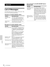
...IMG-FLIP" in the SYSTEM menu or "D-ZOOM" in the PAN TILT ZOOM menu. Indicators on the Optical Multiplex Unit. Messages for the BRC-300/300P camera Message Meaning/remedies Please restart system You are inserted into the memory (POSITION 1-6), the message will appear for 2 seconds. White balance active ... the Optical Multiplex Unit. Turn off the power of the Optical Multiplex Unit and remove either of the camera, and consult with your Sony dealer. White balance active While the white balance adjustment is complete, it on . Take the necessary measures shown below. The tally ...
...IMG-FLIP" in the SYSTEM menu or "D-ZOOM" in the PAN TILT ZOOM menu. Indicators on the Optical Multiplex Unit. Messages for the BRC-300/300P camera Message Meaning/remedies Please restart system You are inserted into the memory (POSITION 1-6), the message will appear for 2 seconds. White balance active ... the Optical Multiplex Unit. Turn off the power of the Optical Multiplex Unit and remove either of the camera, and consult with your Sony dealer. White balance active While the white balance adjustment is complete, it on . Take the necessary measures shown below. The tally ...

Operating Instructions
Page 57
The initial settings of the camera are in bold. Menu Configuration The menus of each item are configured as described below. EXPOSURE MODE FULL AUTO MANUAL SHUTTER Pri IRIS Pri BRIGHT -3, 0, 3, 6, 9, 12, 15, 18 dB BRC-300: 1/4, 1/8, 1/15, 1/30, 1/60, 1/90, 1/100, 1/125, 1/180, 1/250, ...1/350, 1/500, 1/725, 1/1000, 1/1500, 1/2000, 1/3000, 1/4000, 1/6000, 1/10000 (sec.) BRC-300P: 1/3, 1/6, 1/12, 1/25, 1/50, 1/75, 1/100, 1/120, 1/150, 1/215, 1/300, 1/425, 1/600, 1/1000, 1/1250, 1/1750,...
The initial settings of the camera are in bold. Menu Configuration The menus of each item are configured as described below. EXPOSURE MODE FULL AUTO MANUAL SHUTTER Pri IRIS Pri BRIGHT -3, 0, 3, 6, 9, 12, 15, 18 dB BRC-300: 1/4, 1/8, 1/15, 1/30, 1/60, 1/90, 1/100, 1/125, 1/180, 1/250, ...1/350, 1/500, 1/725, 1/1000, 1/1500, 1/2000, 1/3000, 1/4000, 1/6000, 1/10000 (sec.) BRC-300P: 1/3, 1/6, 1/12, 1/25, 1/50, 1/75, 1/100, 1/120, 1/150, 1/215, 1/300, 1/425, 1/600, 1/1000, 1/1250, 1/1750,...
Operating Instructions
Page 60
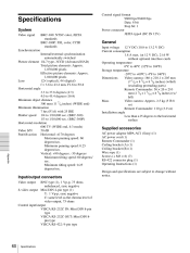
...degrees/ sec. Minimum panning speed: 0.25 degrees/sec. Supplied accessories AC power adaptor MPA-AC1 (Sony) (1) AC power cord (1) Remote Commander (1) Ceiling bracket (A) (1) Ceiling bracket (B) (1) Wire rope... Maximum panning speed: 60 degrees/sec. Specifications System Video signal BRC-300: NTSC color, JEITA standards BRC-300P: PAL color, CCIR standards Control signal format 9600 bps/...: 56 × 26 × 210 mm (2 1/4 × 1 1/16 × 8 3/8 inches) (w/ h/d) Mass Video camera: Approx. 2.5 kg (5 lb 8 oz) Remote Commander: 110 g (3.9 oz) Installation angle Less than ±15 degrees to the...
...degrees/ sec. Minimum panning speed: 0.25 degrees/sec. Supplied accessories AC power adaptor MPA-AC1 (Sony) (1) AC power cord (1) Remote Commander (1) Ceiling bracket (A) (1) Ceiling bracket (B) (1) Wire rope... Maximum panning speed: 60 degrees/sec. Specifications System Video signal BRC-300: NTSC color, JEITA standards BRC-300P: PAL color, CCIR standards Control signal format 9600 bps/...: 56 × 26 × 210 mm (2 1/4 × 1 1/16 × 8 3/8 inches) (w/ h/d) Mass Video camera: Approx. 2.5 kg (5 lb 8 oz) Remote Commander: 110 g (3.9 oz) Installation angle Less than ±15 degrees to the...

Operating Instructions
Page 64
Pin Assignments BRC-300/300P Video Camera VISCA RS-422 connector (connector plug 9-pin) 1 2 3 4 5 6 7 8 9 VISCA RS-232C OUT connector (mini DIN 8-pin, female) VISCA RS-232C OUT VISCA RS-422 Pin No. 1 2 3 4 5 6 7 8 9 ... TXD IN GND RXD IN GND No Connection No Connection * The SIRCS OUT function is selectable with the BOTTOM switch on the bottom of the camera. 64 Specifications
Pin Assignments BRC-300/300P Video Camera VISCA RS-422 connector (connector plug 9-pin) 1 2 3 4 5 6 7 8 9 VISCA RS-232C OUT connector (mini DIN 8-pin, female) VISCA RS-232C OUT VISCA RS-422 Pin No. 1 2 3 4 5 6 7 8 9 ... TXD IN GND RXD IN GND No Connection No Connection * The SIRCS OUT function is selectable with the BOTTOM switch on the bottom of the camera. 64 Specifications


