
Operating Instructions
Page 2
... instruction manual, may result in hazards such as a power supply source. For the customers in Canada This Class A digital apparatus complies with this manual must be easily accessible. This equipment generates, uses, and can radiate radio frequency energy and, if not installed and used with Canadian ICES-003. Record these numbers whenever you call upon your authority to qualified personnel only. Owner's Record The model...
... instruction manual, may result in hazards such as a power supply source. For the customers in Canada This Class A digital apparatus complies with this manual must be easily accessible. This equipment generates, uses, and can radiate radio frequency energy and, if not installed and used with Canadian ICES-003. Record these numbers whenever you call upon your authority to qualified personnel only. Owner's Record The model...

Operating Instructions
Page 3
... CCD Phenomena ...5 Adjusting and Setting With Menus About On-Screen Menus ...23 Main Menu ...23 Setting Menus ...23 Operation Through Menus ...24 Menu Operation Using the Supplied Remote Commander ...24 Menu Operation Using the RM-BR300 Remote Control Unit ...25 EXPOSURE Menu ...26 FOCUS Menu ...27 WHITE BALANCE Menu ...27 PAN TILT ZOOM Menu ...28 PICTURE Menu ...29 SYSTEM Menu ...29 ANALOG OUT Menu ...30 Overview Features ...6 System Components ...7 Supplied Components and Accessories ...7 Optional Products ...8 System Configuration ...10 Operating a BRC-300/300P Camera Using the Supplied...
... CCD Phenomena ...5 Adjusting and Setting With Menus About On-Screen Menus ...23 Main Menu ...23 Setting Menus ...23 Operation Through Menus ...24 Menu Operation Using the Supplied Remote Commander ...24 Menu Operation Using the RM-BR300 Remote Control Unit ...25 EXPOSURE Menu ...26 FOCUS Menu ...27 WHITE BALANCE Menu ...27 PAN TILT ZOOM Menu ...28 PICTURE Menu ...29 SYSTEM Menu ...29 ANALOG OUT Menu ...30 Overview Features ...6 System Components ...7 Supplied Components and Accessories ...7 Optional Products ...8 System Configuration ...10 Operating a BRC-300/300P Camera Using the Supplied...

Operating Instructions
Page 4
... ...46 Connecting the RM-BR300 Remote Control Unit ...47 Connecting a Video Monitor, VTR, etc. Equipped with SDI Input Connector ...51 Connecting the BRU-300/300P Optical Multiplex Unit ...51 Connecting a Video Switcher ...52 Connecting a Sync Signal Generator ...53 Appendix List of Messages ...54 Troubleshooting ...55 Menu Configuration ...57 Presetting Items ...59 Specifications ...60 Dimensions ...61 Pin Assignments ...64 Wiring Diagram of VISCA RS-422 Connection ...67 Using the VISCA RS-422 Connector Plug ...68...
... ...46 Connecting the RM-BR300 Remote Control Unit ...47 Connecting a Video Monitor, VTR, etc. Equipped with SDI Input Connector ...51 Connecting the BRU-300/300P Optical Multiplex Unit ...51 Connecting a Video Switcher ...52 Connecting a Sync Signal Generator ...53 Appendix List of Messages ...54 Troubleshooting ...55 Menu Configuration ...57 Presetting Items ...59 Specifications ...60 Dimensions ...61 Pin Assignments ...64 Wiring Diagram of VISCA RS-422 Connection ...67 Using the VISCA RS-422 Connector Plug ...68...

Operating Instructions
Page 6
... Optical Multiplex Card. As the camera supports the industry-standard VISCA camera protocol, up to the camera, allowing use of a primary-color optical prism enables shooting with superior color reproduction. • A fine image is remarkably quiet, even at low speed realizes a minimum pan/ tilt speed of the optical fiber cable enables an economical and easy system configuration for signal processing. Overview Built-in interface card slot The camera is equipped...
... Optical Multiplex Card. As the camera supports the industry-standard VISCA camera protocol, up to the camera, allowing use of a primary-color optical prism enables shooting with superior color reproduction. • A fine image is remarkably quiet, even at low speed realizes a minimum pan/ tilt speed of the optical fiber cable enables an economical and easy system configuration for signal processing. Overview Built-in interface card slot The camera is equipped...

Operating Instructions
Page 17
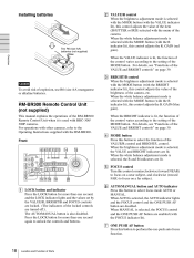
...Parts 17 For the camera number setting, see "Operating Multiple Cameras with the Remote Commander. Location and Function of the camera. I PAN-TILT RESET button Press this button to display the main menu. Press the T (telephoto) side of the button to zoom in the memory of the B/b buttons. F POWER switch Press this button to enable the backlight compensation. Remote Commander (supplied) POWER C DATA SCREEN button Press this button to reset the pan/tilt position. Note 6 CAMERA SELECT 1 2 3 STD AUTO 1 FOCUS 2 3 MANUAL FAR NEAR DATA SCREEN BACK LIGHT 7 Pan/tilt and zoom...
...Parts 17 For the camera number setting, see "Operating Multiple Cameras with the Remote Commander. Location and Function of the camera. I PAN-TILT RESET button Press this button to display the main menu. Press the T (telephoto) side of the button to zoom in the memory of the B/b buttons. F POWER switch Press this button to enable the backlight compensation. Remote Commander (supplied) POWER C DATA SCREEN button Press this button to reset the pan/tilt position. Note 6 CAMERA SELECT 1 2 3 STD AUTO 1 FOCUS 2 3 MANUAL FAR NEAR DATA SCREEN BACK LIGHT 7 Pan/tilt and zoom...
Operating Instructions
Page 18
... camera, etc. The AUTO/MANUAL button is used with BRC-300/ 300P cameras. When the VALUE indicator is selected with the MODE button (with the BRIGHT indicator lit), this control adjusts the value of the brightness of the RM-BR300 Remote Control Unit when it is also disabled. GAIN (blue gain). Front 890qaqsqd 1 2 3 4 5 6 7 VALUE LOCK PANEL LIGHT RESET BLACK LIGHT PAN-TILT RESET ONE PUSH AWB qf MENU qg - R BRIGHT + PRESET MODE POSITION...
... camera, etc. The AUTO/MANUAL button is used with BRC-300/ 300P cameras. When the VALUE indicator is selected with the MODE button (with the BRIGHT indicator lit), this control adjusts the value of the brightness of the RM-BR300 Remote Control Unit when it is also disabled. GAIN (blue gain). Front 890qaqsqd 1 2 3 4 5 6 7 VALUE LOCK PANEL LIGHT RESET BLACK LIGHT PAN-TILT RESET ONE PUSH AWB qf MENU qg - R BRIGHT + PRESET MODE POSITION...

Operating Instructions
Page 19
... turn off the power of the buttons to 16. Press it forward or backward, the camera tilts. L PAN-TILT RESET button Press this button to perform the one of the camera corresponding to the pressed POSITION button. When you turn on the top of the camera corresponding to the pressed button. When the menu of the camera is displayed The joystick is used for one or two seconds with the WHITE BALANCE menu...
... turn off the power of the buttons to 16. Press it forward or backward, the camera tilts. L PAN-TILT RESET button Press this button to perform the one of the camera corresponding to the pressed POSITION button. When you turn on the top of the camera corresponding to the pressed button. When the menu of the camera is displayed The joystick is used for one or two seconds with the WHITE BALANCE menu...

Operating Instructions
Page 23
... zoom operations while the menu is displayed. Adjusting and Setting With Menus Setting Menus The setting menu selected on the main menu is displayed. Main Menu To display the main menu, press the DATA SCREEN button on the supplied Remote Commander or the MENU button on the RM-BR300 Remote Control Unit. 1 Setting menu The name of the camera, while observing menus displayed on -screen menus before starting menu operations. Analog-Card >EXPOSURE FOCUS WHITE BALANCE PAN TILT ZOOM PICTURE SYSTEM ANALOG OUT 1 Cursor Selects a setting menu. To change...
... zoom operations while the menu is displayed. Adjusting and Setting With Menus Setting Menus The setting menu selected on the main menu is displayed. Main Menu To display the main menu, press the DATA SCREEN button on the supplied Remote Commander or the MENU button on the RM-BR300 Remote Control Unit. 1 Setting menu The name of the camera, while observing menus displayed on -screen menus before starting menu operations. Analog-Card >EXPOSURE FOCUS WHITE BALANCE PAN TILT ZOOM PICTURE SYSTEM ANALOG OUT 1 Cursor Selects a setting menu. To change...

Operating Instructions
Page 25
...-RECEIVE IMG-FLIP PAN REVERSE TILT REVERSE DISPLAY INFO 1 2,4,5 VALUE LOCK PANEL LIGHT RESET BLACK LIGHT PAN-TILT RESET ONE PUSH AWB MENU - Analog-Card >EXPOSURE FOCUS WHITE BALANCE PAN TILT ZOOM PICTURE SYSTEM ANALOG OUT To return to the normal display Pres the MENU button when the main menu is displayed. 2 3 Move the cursor to the menu item to the main menu Press the MENU button. The main menu appears. Operation Through Menus 25 Menu Operation Using the RMBR300 Remote Control Unit 5 Change the...
...-RECEIVE IMG-FLIP PAN REVERSE TILT REVERSE DISPLAY INFO 1 2,4,5 VALUE LOCK PANEL LIGHT RESET BLACK LIGHT PAN-TILT RESET ONE PUSH AWB MENU - Analog-Card >EXPOSURE FOCUS WHITE BALANCE PAN TILT ZOOM PICTURE SYSTEM ANALOG OUT To return to the normal display Pres the MENU button when the main menu is displayed. 2 3 Move the cursor to the menu item to the main menu Press the MENU button. The main menu appears. Operation Through Menus 25 Menu Operation Using the RMBR300 Remote Control Unit 5 Change the...

Operating Instructions
Page 28
... period and output from the VIDEO and S VIDEO connectors of the camera and the connector on the optional interface card inserted into the card slot. +35359 STEP LEFT END (170°) -35241 STEP RIGHT END (170°) 28 PAN TILT ZOOM Menu Note Regardless of the D-ZOOM ON/OFF setting, images shot by LIMIT. When you set TILT to ON, UP and DOWN appear and you change IM...
... period and output from the VIDEO and S VIDEO connectors of the camera and the connector on the optional interface card inserted into the card slot. +35359 STEP LEFT END (170°) -35241 STEP RIGHT END (170°) 28 PAN TILT ZOOM Menu Note Regardless of the D-ZOOM ON/OFF setting, images shot by LIMIT. When you set TILT to ON, UP and DOWN appear and you change IM...

Operating Instructions
Page 31
... turn the camera on the screen. POWER CAMERA SELECT 1 FOCUS AUTO FAR NEAR MANUAL 2 3 DATA SCREEN BACK LIGHT POWER STANDBY lights. To move the camera with the POWER switch on the Remote Commander. To reset the setting, press the 1 (STD) button while holding down the B or b button. 1 2 Connect the camera to an AC outlet using the Remote Commander As long as the camera is pressed. For details, see "Installation" (page 42) and "Connections" (page 46). Pan/Tilt and Zoom Operation Panning and Tilting...
... turn the camera on the screen. POWER CAMERA SELECT 1 FOCUS AUTO FAR NEAR MANUAL 2 3 DATA SCREEN BACK LIGHT POWER STANDBY lights. To move the camera with the POWER switch on the Remote Commander. To reset the setting, press the 1 (STD) button while holding down the B or b button. 1 2 Connect the camera to an AC outlet using the Remote Commander As long as the camera is pressed. For details, see "Installation" (page 42) and "Connections" (page 46). Pan/Tilt and Zoom Operation Panning and Tilting...

Operating Instructions
Page 35
... connected cameras and the RM-BR300 Remote Control Unit. R BRIGHT + PRESET MODE POSITION SHIFT 1 9 STD 2 10 REV 3 11 4 12 5 13 6 14 7 15 8 16 - The camera will automatically pan and tilt and be controlled simply by default.) Turn on the power of the camera before the power of the Remote Control Unit Operation Using the RM-BR300 Remote Control Unit PAN-TILT RESET ONE PUSH AWB MENU - Turning on the Remote Control Unit. To turn on/off with the POWER button on the Power STANDBY lights. 1 2 RESET VALUE LOCK PANEL LIGHT RESET...
... connected cameras and the RM-BR300 Remote Control Unit. R BRIGHT + PRESET MODE POSITION SHIFT 1 9 STD 2 10 REV 3 11 4 12 5 13 6 14 7 15 8 16 - The camera will automatically pan and tilt and be controlled simply by default.) Turn on the power of the camera before the power of the Remote Control Unit Operation Using the RM-BR300 Remote Control Unit PAN-TILT RESET ONE PUSH AWB MENU - Turning on the Remote Control Unit. To turn on/off with the POWER button on the Power STANDBY lights. 1 2 RESET VALUE LOCK PANEL LIGHT RESET...

Operating Instructions
Page 36
... CAMERA AUTO FOCUS AUTO MANUAL POWER 1 2 3 4 5 6 7 NEAR FAR ONE PUSH AF POWER 2 3 1 Turn on the screen, incline the joystick in the connected order. While checking the picture on the power of the camera and the RMBR300 Remote Control Unit. The number of the lit CAMERA buttons indicates how many cameras have the addresses assigned. Pan/Tilt and Zoom Operation Panning and Tilting L/R DIRECTION REV PAN-TILT RESET 4 1 STD VALUE LOCK PANEL LIGHT RESET BLACK LIGHT PAN-TILT RESET ONE PUSH AWB MENU - R BRIGHT + PRESET MODE POSITION To assign camera addresses manually Set...
... CAMERA AUTO FOCUS AUTO MANUAL POWER 1 2 3 4 5 6 7 NEAR FAR ONE PUSH AF POWER 2 3 1 Turn on the screen, incline the joystick in the connected order. While checking the picture on the power of the camera and the RMBR300 Remote Control Unit. The number of the lit CAMERA buttons indicates how many cameras have the addresses assigned. Pan/Tilt and Zoom Operation Panning and Tilting L/R DIRECTION REV PAN-TILT RESET 4 1 STD VALUE LOCK PANEL LIGHT RESET BLACK LIGHT PAN-TILT RESET ONE PUSH AWB MENU - R BRIGHT + PRESET MODE POSITION To assign camera addresses manually Set...

Operating Instructions
Page 38
... menu of the camera. Adjusting the Camera MODE VALUE/R VALUE LOCK Shooting with a light source behind it in on the screen. (You can use a white wall, etc., instead of the object.) To adjust the white balance automatically Operation Using the RM-BR300 Remote Control Unit 1 Set MODE to ONE PUSH in the WHITE BALANCE menu of the camera. The camera focuses on the subject in the center of the screen automatically. Focusing on the subject. B + L/R DIRECTION CAMERA AUTO FOCUS AUTO MANUAL POWER...
... menu of the camera. Adjusting the Camera MODE VALUE/R VALUE LOCK Shooting with a light source behind it in on the screen. (You can use a white wall, etc., instead of the object.) To adjust the white balance automatically Operation Using the RM-BR300 Remote Control Unit 1 Set MODE to ONE PUSH in the WHITE BALANCE menu of the camera. The camera focuses on the subject in the center of the screen automatically. Focusing on the subject. B + L/R DIRECTION CAMERA AUTO FOCUS AUTO MANUAL POWER...

Operating Instructions
Page 39
... speed control Iris control IRIS Pri Adjusting the Brightness BRIGHT MANUAL Not used Shutter speed control 1 Set MODE to the MODE setting in the EXPOSURE menu, as follows: MODE setting FULL AUTO Function of VALUE control Not used Function of BRIGHT control Exposure compensation level control* Exposure compensation level control* Exposure compensation level control* Brightness level control Iris control Turn toward + for emphasizing red. VALUE Turn toward - MODE BRIGHT Turn toward + for a lower shutter speed or F-number. for weakening blue. - R + Turn...
... speed control Iris control IRIS Pri Adjusting the Brightness BRIGHT MANUAL Not used Shutter speed control 1 Set MODE to the MODE setting in the EXPOSURE menu, as follows: MODE setting FULL AUTO Function of VALUE control Not used Function of BRIGHT control Exposure compensation level control* Exposure compensation level control* Exposure compensation level control* Brightness level control Iris control Turn toward + for emphasizing red. VALUE Turn toward - MODE BRIGHT Turn toward + for a lower shutter speed or F-number. for weakening blue. - R + Turn...

Operating Instructions
Page 43
... ceiling bracket (A). If conditions warrant, make this task an experienced contractor or installer to ensure the wide conversion lens does not come loose and fall and cause serious injury. • Be sure to attach the supplied wire rope to prevent the camera from falling, note the following specifications. 1/4 • Be sure that the connection has not loosened. Use a tripod...
... ceiling bracket (A). If conditions warrant, make this task an experienced contractor or installer to ensure the wide conversion lens does not come loose and fall and cause serious injury. • Be sure to attach the supplied wire rope to prevent the camera from falling, note the following specifications. 1/4 • Be sure that the connection has not loosened. Use a tripod...
Operating Instructions
Page 52
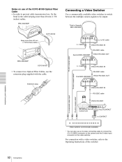
... DC IN 12V RM-BR300 Remote Control Unit TALLY/CONTACT to connect the S VIDEO connector on the camera and the S-video input connector on use of the switcher. 52 Connections Notes on the video switcher. BRC-300/300P Connecting a Video Switcher Use a commercially available video switcher to switch between the multiple camera signals to composite video input A 75-ohm coaxial cable* VISCA RS-232C MODE RS-232C VISCA RS-422 TALLY...
... DC IN 12V RM-BR300 Remote Control Unit TALLY/CONTACT to connect the S VIDEO connector on the camera and the S-video input connector on use of the switcher. 52 Connections Notes on the video switcher. BRC-300/300P Connecting a Video Switcher Use a commercially available video switcher to switch between the multiple camera signals to composite video input A 75-ohm coaxial cable* VISCA RS-232C MODE RS-232C VISCA RS-422 TALLY...
Operating Instructions
Page 54
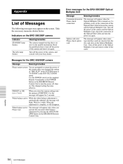
... the Optical Fiber Cable between the camera and the Optical Multiplex Unit. Meaning/remedies The camera stopped moving due to turn the power on the screen. Use the POWER switch on the supplied Remote Commander or the POWER button on the RM-BR300 Remote Control Unit to an error in the PAN TILT ZOOM menu. White balance active The message will appear only when you changed setting becomes effective. Indicators on , if a connection problem occurs in the...
... the Optical Fiber Cable between the camera and the Optical Multiplex Unit. Meaning/remedies The camera stopped moving due to turn the power on the screen. Use the POWER switch on the supplied Remote Commander or the POWER button on the RM-BR300 Remote Control Unit to an error in the PAN TILT ZOOM menu. White balance active The message will appear only when you changed setting becomes effective. Indicators on , if a connection problem occurs in the...

Operating Instructions
Page 55
... the PAN TILT ZOOM menu (page 28). The exposure is not set correctly on the RM-BR300 Remote Control Unit to the same address. The Remote Commander does not work. Appendix The communication baud rate setting of the camera is set the MODE selector on the rear of the camera (page 16) and the DIP switch on the bottom of the Remote Control Unit to turn off the menu from the card slot. Troubleshooting...
... the PAN TILT ZOOM menu (page 28). The exposure is not set correctly on the RM-BR300 Remote Control Unit to the same address. The Remote Commander does not work. Appendix The communication baud rate setting of the camera is set the MODE selector on the rear of the camera (page 16) and the DIP switch on the bottom of the Remote Control Unit to turn off the menu from the card slot. Troubleshooting...

Operating Instructions
Page 59
... cannot reset the setting using the RESET button. ** The default setting is obtained by resetting Position 1. ON NORMAL** WB. a × : Setting items retained in memory when the power is turned off Aperture level a a a a a a a a a a a a a a a a Presetting position number 2 a a a a a a a a a a a a a a a a 3 a a a a a a a a a a a a a a a a 4 a a a a a a a a a a a a a a a a 5 a a a a a a a a a a a a a a a a 6 a a a a a a a a a a a a a a a a Presetting menu items Menu item 1 EXPOSURE MODE EX-COMP SPOT AE FOCUS AUTO/MANUAL NORMAL, INTERVAL, ZOOM Trg WHITE BALANCE MODE WHITE BALANCE MANUAL...
... cannot reset the setting using the RESET button. ** The default setting is obtained by resetting Position 1. ON NORMAL** WB. a × : Setting items retained in memory when the power is turned off Aperture level a a a a a a a a a a a a a a a a Presetting position number 2 a a a a a a a a a a a a a a a a 3 a a a a a a a a a a a a a a a a 4 a a a a a a a a a a a a a a a a 5 a a a a a a a a a a a a a a a a 6 a a a a a a a a a a a a a a a a Presetting menu items Menu item 1 EXPOSURE MODE EX-COMP SPOT AE FOCUS AUTO/MANUAL NORMAL, INTERVAL, ZOOM Trg WHITE BALANCE MODE WHITE BALANCE MANUAL...


