Operating Instructions
Page 1
Sony Corporation Printed in Japan BRC-Z700 © 2007 Sony Corporation 3287510110 3-287-510-11 (1) HD 3CMOS Color Video Camera Operating Instructions Printed on recycled paper.
Sony Corporation Printed in Japan BRC-Z700 © 2007 Sony Corporation 3287510110 3-287-510-11 (1) HD 3CMOS Color Video Camera Operating Instructions Printed on recycled paper.

Operating Instructions
Page 3
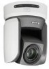
... of Parts 18 Camera 18 Remote Commander (supplied 20 RM-BR300 Remote Control Unit (not supplied 21 BRU-H700 HD Optical Multiplex Unit (not supplied 24 BRBK-MF1 HD Optical Multiplex Card (not supplied) (available with the BRC-Z700 only 25 BRBK-HSD1 HD/SD-SDI Output Card (not supplied) (available with the BRC-Z700 only 25 HFBK...
... of Parts 18 Camera 18 Remote Commander (supplied 20 RM-BR300 Remote Control Unit (not supplied 21 BRU-H700 HD Optical Multiplex Unit (not supplied 24 BRBK-MF1 HD Optical Multiplex Card (not supplied) (available with the BRC-Z700 only 25 BRBK-HSD1 HD/SD-SDI Output Card (not supplied) (available with the BRC-Z700 only 25 HFBK...

Operating Instructions
Page 4
...the Analog Component (YPbPr) Input Connector 63 Connecting a Device Equipped with VISCA RS232C Connector 63 Connecting a Device Equipped with HD-SDI Input Connectors 66 Connecting the BRU-H700 HD Optical Multiplex Unit 66 Connecting a Video Switcher 67 Connecting a Sync Signal Generator 68 Appendix List of Messages 70 Troubleshooting 71 ...Pin Assignments 86 Wiring Diagram of VISCA RS-422 Connection 89 Using the VISCA RS-422 Connector Plug ...... 90 4 Table of the Camera Moving to an AC Outlet 61 Connecting the RM-BR300 Remote Control Unit 62 Connecting a Monitor, etc. Adjusting the...
...the Analog Component (YPbPr) Input Connector 63 Connecting a Device Equipped with VISCA RS232C Connector 63 Connecting a Device Equipped with HD-SDI Input Connectors 66 Connecting the BRU-H700 HD Optical Multiplex Unit 66 Connecting a Video Switcher 67 Connecting a Sync Signal Generator 68 Appendix List of Messages 70 Troubleshooting 71 ...Pin Assignments 86 Wiring Diagram of VISCA RS-422 Connection 89 Using the VISCA RS-422 Connector Plug ...... 90 4 Table of the Camera Moving to an AC Outlet 61 Connecting the RM-BR300 Remote Control Unit 62 Connecting a Monitor, etc. Adjusting the...
Operating Instructions
Page 6
...card slot for SD output at the moment and use of the BRBK-MF1 HD Optical Multiplex Card, CCFC-M100HG Optical Fiber Cable and BRU-H700 Optical Multiplex Unit, and Sony's unique camera connection technology and optical digital multiplex transmission technology allows a long distance transmission ...of camera images up to a 35-mm camera). You can use the connectors for the optional BRBK-HSD1 HD/SD-SDI Output Card and BRBK-MF1 HD Optical Multiplex Card...
...card slot for SD output at the moment and use of the BRBK-MF1 HD Optical Multiplex Card, CCFC-M100HG Optical Fiber Cable and BRU-H700 Optical Multiplex Unit, and Sony's unique camera connection technology and optical digital multiplex transmission technology allows a long distance transmission ...of camera images up to a 35-mm camera). You can use the connectors for the optional BRBK-HSD1 HD/SD-SDI Output Card and BRBK-MF1 HD Optical Multiplex Card...

Operating Instructions
Page 7
... MPA-AC1 (Sony) (1) AC power cord (1) USA and Canadian model 7 System Components The camera also has an analog component/ RGB output connector as the accessories supplied with an external video sync function to support multiple system configurations, a variety of the camera allows you to... equipment. External video sync function The camera is selected at a glance. System Components In order to synchronize the camera images on multiple cameras. Supplied Components and Accessories Before using the camera, make sure it is equipped with the camera. Tally lamp The tally lamp of ...
... MPA-AC1 (Sony) (1) AC power cord (1) USA and Canadian model 7 System Components The camera also has an analog component/ RGB output connector as the accessories supplied with an external video sync function to support multiple system configurations, a variety of the camera allows you to... equipment. External video sync function The camera is selected at a glance. System Components In order to synchronize the camera images on multiple cameras. Supplied Components and Accessories Before using the camera, make sure it is equipped with the camera. Tally lamp The tally lamp of ...

Operating Instructions
Page 8
... zoom operations. Supplied accessories: AC power adaptor (1), AC power cord (1), RS-232C connecting cable (3 m) (1), RS-422 connector plug (2) BRBK-MF1 HD Optical Multiplex Card Insert the card into the camera to seven cameras. Overview European model Screw 3M3 × 8 (7)/Stainless screw 3M4 × 8 (1) Remote commander (1) RS-422 connector plug (1) Two R6 (size AA...
... zoom operations. Supplied accessories: AC power adaptor (1), AC power cord (1), RS-232C connecting cable (3 m) (1), RS-422 connector plug (2) BRBK-MF1 HD Optical Multiplex Card Insert the card into the camera to seven cameras. Overview European model Screw 3M3 × 8 (7)/Stainless screw 3M4 × 8 (1) Remote commander (1) RS-422 connector plug (1) Two R6 (size AA...

Operating Instructions
Page 9
...-SDI Output Card Video Switcher (commercially available) Overview Insert the card into the BRC-Z700 camera. VCL-HG0862K Wide Conversion Lens The HD Optical Multiplex Unit allows a connection up to of an SD-SDI signal conforming to SMPTE292M serial digital interface standards, or output of 1,000 m (3,281 feet) ...
...-SDI Output Card Video Switcher (commercially available) Overview Insert the card into the BRC-Z700 camera. VCL-HG0862K Wide Conversion Lens The HD Optical Multiplex Unit allows a connection up to of an SD-SDI signal conforming to SMPTE292M serial digital interface standards, or output of 1,000 m (3,281 feet) ...

Operating Instructions
Page 10
An audio signal of the video signal from the board. HFBK-XG1 XGA Interface Board The board allows output of an analog video signal (component/RGB). HFBK-TS1 HDV Interface Board The board allows conversion of the HD-SDI signal is not output from the camera and the input audio signal into the signal conforming to the VESA standards (VGA, XGA or WXGA). Overview HFBK-HD1 HD Interface Board The board allows output of an HD-SDI signal conforming to SMPTE292M serial digital interface standards, or output of a signal conforming to the HDV standards. 10 System Components
An audio signal of the video signal from the board. HFBK-XG1 XGA Interface Board The board allows output of an analog video signal (component/RGB). HFBK-TS1 HDV Interface Board The board allows conversion of the HD-SDI signal is not output from the camera and the input audio signal into the signal conforming to the VESA standards (VGA, XGA or WXGA). Overview HFBK-HD1 HD Interface Board The board allows output of an HD-SDI signal conforming to SMPTE292M serial digital interface standards, or output of a signal conforming to the HDV standards. 10 System Components
Operating Instructions
Page 11
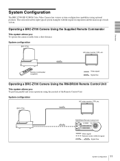
...Remote Commander (supplied) Video signal Signal flow Operating a BRC-Z700 Camera Using the RM-BR300 Remote Control Unit This system allows you : To operate the camera readily from a short distance System configuration BRC-Z700 HD video monitor, VTR, etc. This section describes eight ...(VISCA) signal , Signal flow 11 System Configuration System Configuration The BRC-Z700 HD 3CMOS Color Video Camera has various system configuration capabilities using the joystick of each system. Operating a BRC-Z700 Camera Using the Supplied Remote Commander This system allows you : To perform...
...Remote Commander (supplied) Video signal Signal flow Operating a BRC-Z700 Camera Using the RM-BR300 Remote Control Unit This system allows you : To operate the camera readily from a short distance System configuration BRC-Z700 HD video monitor, VTR, etc. This section describes eight ...(VISCA) signal , Signal flow 11 System Configuration System Configuration The BRC-Z700 HD 3CMOS Color Video Camera has various system configuration capabilities using the joystick of each system. Operating a BRC-Z700 Camera Using the Supplied Remote Commander This system allows you : To perform...

Operating Instructions
Page 12
Overview Operating Multiple BRC-Z700 Cameras Using the RM-BR300 Remote Control Unit This system allows you: • To operate up to seven cameras remotely using a single Remote Control Unit • To perform pan/tilt and zoom operations using the joystick System configuration BRC-Z700 HD video monitor, VTR, etc. BRC-Z700 BRC-Z700 Video switcher RM-BR300 Remote Control Unit Video signal Remote control (VISCA) signal Tally/contact signal , Signal flow 12 System Configuration
Overview Operating Multiple BRC-Z700 Cameras Using the RM-BR300 Remote Control Unit This system allows you: • To operate up to seven cameras remotely using a single Remote Control Unit • To perform pan/tilt and zoom operations using the joystick System configuration BRC-Z700 HD video monitor, VTR, etc. BRC-Z700 BRC-Z700 Video switcher RM-BR300 Remote Control Unit Video signal Remote control (VISCA) signal Tally/contact signal , Signal flow 12 System Configuration

Operating Instructions
Page 13
... place using the CCFC-M100HG Optical Fiber Cable and turn on the power of the BRU-H700 HD Optical Multiplex Unit. • The BRC-Z700 camera does not operate if nothing is inserted into the camera. Use the connectors and switches on the rear of the BRUH700 Optical Multiplex Unit instead. •...Optical Fiber Cable cannot be used with this system. 13 System Configuration To operate the camera, connect the BRU-H700 Optical Multiplex Unit to the BRBK-MF1 HD Optical Multiplex Card inserted into the BRC-Z700 camera, the EXT SYNC IN connector, VISCA RS-232C IN/OUT connectors and VISCA RS...
... place using the CCFC-M100HG Optical Fiber Cable and turn on the power of the BRU-H700 HD Optical Multiplex Unit. • The BRC-Z700 camera does not operate if nothing is inserted into the camera. Use the connectors and switches on the rear of the BRUH700 Optical Multiplex Unit instead. •...Optical Fiber Cable cannot be used with this system. 13 System Configuration To operate the camera, connect the BRU-H700 Optical Multiplex Unit to the BRBK-MF1 HD Optical Multiplex Card inserted into the BRC-Z700 camera, the EXT SYNC IN connector, VISCA RS-232C IN/OUT connectors and VISCA RS...

Operating Instructions
Page 14
...; To transmit the video signal and control signal of the cameras to a distant place using the Optical Fiber Cable System configuration BRC-Z700 BRU-H700 Optical CCFC-M100HG Multiplex Unit Optical Fiber Cable HD video monitor, VTR, etc. BRC-Z700 BRBK-MF1 HD Optical Multiplex Card BRC-Z700 CCFC-M100HG BRBK-MF1 BRU-H700 Video switcher CCFC-M100HG BRBK...
...; To transmit the video signal and control signal of the cameras to a distant place using the Optical Fiber Cable System configuration BRC-Z700 BRU-H700 Optical CCFC-M100HG Multiplex Unit Optical Fiber Cable HD video monitor, VTR, etc. BRC-Z700 BRBK-MF1 HD Optical Multiplex Card BRC-Z700 CCFC-M100HG BRBK-MF1 BRU-H700 Video switcher CCFC-M100HG BRBK...

Operating Instructions
Page 15
VISCA-controllable camera BRC-Z700 CCFC-M100HG BRU-H700 BRC-Z700 BRBK-MF1 CCFC-M100HG Optical Fiber Cable BRBK-MF1 HD Optical Multiplex Card Video signal Remote control (VISCA) signal Tally/contact signal , Signal flow BRU-H700 HD Optical Multiplex Unit Video switcher RM-BR300 Remote Control Unit 15 System Configuration Overview Using BRC-Z700 Cameras and VISCA-controllable Cameras in the...
VISCA-controllable camera BRC-Z700 CCFC-M100HG BRU-H700 BRC-Z700 BRBK-MF1 CCFC-M100HG Optical Fiber Cable BRBK-MF1 HD Optical Multiplex Card Video signal Remote control (VISCA) signal Tally/contact signal , Signal flow BRU-H700 HD Optical Multiplex Unit Video switcher RM-BR300 Remote Control Unit 15 System Configuration Overview Using BRC-Z700 Cameras and VISCA-controllable Cameras in the...

Operating Instructions
Page 16
... signal of the camera, and the audio signal input to the BRBK-MF1 Optical Multiplex Card to a distant place using the Optical Fiber Cable System configuration BRC-Z700 Microphone Microphone amplifier HD video monitor Speakers Audio amplifier BRBK-MF1 HD Optical Multiplex Card ...CCFC-M100HG Optical Fiber Cable BRU-H700 HD Optical Multiplex Unit Video signal Audio line signal Remote control (...
... signal of the camera, and the audio signal input to the BRBK-MF1 Optical Multiplex Card to a distant place using the Optical Fiber Cable System configuration BRC-Z700 Microphone Microphone amplifier HD video monitor Speakers Audio amplifier BRBK-MF1 HD Optical Multiplex Card ...CCFC-M100HG Optical Fiber Cable BRU-H700 HD Optical Multiplex Unit Video signal Audio line signal Remote control (...

Operating Instructions
Page 17
... allows you insert the HFBK-TS1 HDV Interface Board into the BRU-H700 • To input the video signal of the camera and the audio signal via the Optical Fiber Cable as an audio signal conforming to HDV standards from the HFBK-TS1 through ...camera, and the audio signal input to the BRBK-MF1 Optical Multiplex Card to a distant place using the Optical Fiber Cable • To output the audio signal transmitted via the HFBK-TS1 HDV Interface Board simultaneously to the HDV video equipment System configuration BRC-Z700 Microphone BRBK-MF1 HD Optical Multiplex Card Microphone amplifier HD...
... allows you insert the HFBK-TS1 HDV Interface Board into the BRU-H700 • To input the video signal of the camera and the audio signal via the Optical Fiber Cable as an audio signal conforming to HDV standards from the HFBK-TS1 through ...camera, and the audio signal input to the BRBK-MF1 Optical Multiplex Card to a distant place using the Optical Fiber Cable • To output the audio signal transmitted via the HFBK-TS1 HDV Interface Board simultaneously to the HDV video equipment System configuration BRC-Z700 Microphone BRBK-MF1 HD Optical Multiplex Card Microphone amplifier HD...

Operating Instructions
Page 18
...motor is lowered or the motor has stopped regardless of the camera does not function. Overview Location and Function of Parts Camera Front 12 3 F STANDBY lamp Lights when the camera is turned off of the tally lamp. D SONY and HD nameplates Pull them out to the RM-BR300 Remote Control Unit ...(not supplied). M VISCA RS-232C IN connector Connect to turn them over and attach upside down if necessary. When you connect multiple cameras, connect it...
...motor is lowered or the motor has stopped regardless of the camera does not function. Overview Location and Function of Parts Camera Front 12 3 F STANDBY lamp Lights when the camera is turned off of the tally lamp. D SONY and HD nameplates Pull them out to the RM-BR300 Remote Control Unit ...(not supplied). M VISCA RS-232C IN connector Connect to turn them over and attach upside down if necessary. When you connect multiple cameras, connect it...
Operating Instructions
Page 23
.../300P EVI-D70/D70P EVI-D100/D100P EVI-D30/D30P SNC-RZ30N BRC-H700 BRC-Z700 Note Set the selector to position 0. For other connections, set the selector to position 7 when all the connected cameras are BRC-Z700s. X TALLY/CONTACT connector This connector is short-circuited against the connected switcher and the tally .../OFF wa ws wd wf wg wh wj wk U MODE selector Select the position corresponding to the VISCAcontrollable camera to the VISCA RS-422 connector of the camera or the BRU-H700 HD Optical Multiplex Unit. An RS-422 connector plug is not effective. TALLY: The tally lamp of the...
.../300P EVI-D70/D70P EVI-D100/D100P EVI-D30/D30P SNC-RZ30N BRC-H700 BRC-Z700 Note Set the selector to position 0. For other connections, set the selector to position 7 when all the connected cameras are BRC-Z700s. X TALLY/CONTACT connector This connector is short-circuited against the connected switcher and the tally .../OFF wa ws wd wf wg wh wj wk U MODE selector Select the position corresponding to the VISCAcontrollable camera to the VISCA RS-422 connector of the camera or the BRU-H700 HD Optical Multiplex Unit. An RS-422 connector plug is not effective. TALLY: The tally lamp of the...

Operating Instructions
Page 24
...Connect to overlap the menu. When you connect multiple cameras, connect it on the monitor and check the error message. Flashing in red: Abnormal operation of the BRBKH700 HD Optical Multiplex Card installed in the BRC-H700 camera using the CCFC-M100HG Optical Fiber Cable. Check also...the daisy chain connection. For the error message, see "List of the BRC-H700 camera before you turn on the HD Optical Multiplex Unit. Set it to the optical connector of the HD Optical Multiplex Unit. Overview BRU-H700 HD Optical Multiplex Unit (not supplied) Front 12 3 A Power switch Turns...
...Connect to overlap the menu. When you connect multiple cameras, connect it on the monitor and check the error message. Flashing in red: Abnormal operation of the BRBKH700 HD Optical Multiplex Card installed in the BRC-H700 camera using the CCFC-M100HG Optical Fiber Cable. Check also...the daisy chain connection. For the error message, see "List of the BRC-H700 camera before you turn on the HD Optical Multiplex Unit. Set it to the optical connector of the HD Optical Multiplex Unit. Overview BRU-H700 HD Optical Multiplex Unit (not supplied) Front 12 3 A Power switch Turns...
Operating Instructions
Page 25
...communication settings. You can be input. B HD/SD select switch Set the switch to SD to supply SD-SDI signals and HD to "0". When you turn on the camera. • Do not push the switch forcibly with the BRC-Z700 only) BRBK-HSD1 1 SDI OUTPUT 2 SD HD A SDI OUTPUT connectors (BNC type) ...Supplies down the RESET button on the BRU-H700 HD Optical Multiplex Unit via the ...
...communication settings. You can be input. B HD/SD select switch Set the switch to SD to supply SD-SDI signals and HD to "0". When you turn on the camera. • Do not push the switch forcibly with the BRC-Z700 only) BRBK-HSD1 1 SDI OUTPUT 2 SD HD A SDI OUTPUT connectors (BNC type) ...Supplies down the RESET button on the BRU-H700 HD Optical Multiplex Unit via the ...

Operating Instructions
Page 26
...Supplies analog video signals (component or RGB). The aspect ratio can be selected in the HDSDI menu of the camera. The input audio signals are converted into the BRUH700 HD Optical Multiplex Unit, the DIP switches cannot be used . B DIP switches (inside the cap) When this ...LINK (HDV) OUT A AUDIO L/R jacks (phono type) Input audio signals (stereo). The output signal can be specified in the DOWN CONVERTER menu of the camera. D SD-SDI connector (BNC type) Supplies down-converted SD-SDI signals that comply with the BRU-H700 only) 1 MONITOR HFBK-XG1 2 A MONITOR connector...
...Supplies analog video signals (component or RGB). The aspect ratio can be selected in the HDSDI menu of the camera. The input audio signals are converted into the BRUH700 HD Optical Multiplex Unit, the DIP switches cannot be used . B DIP switches (inside the cap) When this ...LINK (HDV) OUT A AUDIO L/R jacks (phono type) Input audio signals (stereo). The output signal can be specified in the DOWN CONVERTER menu of the camera. D SD-SDI connector (BNC type) Supplies down-converted SD-SDI signals that comply with the BRU-H700 only) 1 MONITOR HFBK-XG1 2 A MONITOR connector...


