
Operating Instructions
Page 2
... into account. 2 This product has no power switch. Disconnect device of this product is likely to comply with the cable. Please ensure that interference should be required to Subpart B of Part 15 of this equipment is capable of supporting four times the weight of the AC adapter. WARNING (For Installers only) Instruction for a digital device pursuant to take adequate measures...
... into account. 2 This product has no power switch. Disconnect device of this product is likely to comply with the cable. Please ensure that interference should be required to Subpart B of Part 15 of this equipment is capable of supporting four times the weight of the AC adapter. WARNING (For Installers only) Instruction for a digital device pursuant to take adequate measures...

Operating Instructions
Page 3
...-OUTPUT Menu 41 HDV Menu 41 Operation Using the Supplied Remote Commander Turning on the Power 42 Pan/Tilt and Zoom Operation 42 Panning and Tilting 42 Zooming 43 Operating Multiple Cameras with the Remote Commander 43 Adjusting the Camera 44 Focusing on the Power 46 Operating Multiple Cameras 46 Pan/Tilt and Zoom Operation 47 Panning and Tilting 47 Zooming 49 3 Table of Contents controllable Cameras in the Same System ..... 15 Transmitting Audio Signals Using the BRU-H700 16 Using the BRBK-MF1 HD Optical Multiplex Card...
...-OUTPUT Menu 41 HDV Menu 41 Operation Using the Supplied Remote Commander Turning on the Power 42 Pan/Tilt and Zoom Operation 42 Panning and Tilting 42 Zooming 43 Operating Multiple Cameras with the Remote Commander 43 Adjusting the Camera 44 Focusing on the Power 46 Operating Multiple Cameras 46 Pan/Tilt and Zoom Operation 47 Panning and Tilting 47 Zooming 49 3 Table of Contents controllable Cameras in the Same System ..... 15 Transmitting Audio Signals Using the BRU-H700 16 Using the BRBK-MF1 HD Optical Multiplex Card...

Operating Instructions
Page 4
... 70 Troubleshooting 71 Menu Configuration 73 Presetting Items 78 Specifications 81 Dimensions 83 Pin Assignments 86 Wiring Diagram of VISCA RS-422 Connection 89 Using the VISCA RS-422 Connector Plug ...... 90 4 Table of the Camera Moving to a Preset Position 52 Installation and Connections Installation 53 Attaching an Interface Board 53 Installing the Camera 53 Installing the Camera in Memory - Adjusting the Camera 49 Focusing on a Subject 49 Shooting with VISCA RS422 Connector 64 Connecting a Video Monitor, VTR...
... 70 Troubleshooting 71 Menu Configuration 73 Presetting Items 78 Specifications 81 Dimensions 83 Pin Assignments 86 Wiring Diagram of VISCA RS-422 Connection 89 Using the VISCA RS-422 Connector Plug ...... 90 4 Table of the Camera Moving to a Preset Position 52 Installation and Connections Installation 53 Attaching an Interface Board 53 Installing the Camera 53 Installing the Camera in Memory - Adjusting the Camera 49 Focusing on a Subject 49 Shooting with VISCA RS422 Connector 64 Connecting a Video Monitor, VTR...
Operating Instructions
Page 6
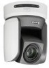
... cable enables an economical and easy system configuration for HD output in 16:9 aspect ratio provides a theater-like wide screen picture. Long-distance image transmission and pan/tilt/zoom control • Combined use them for long distance. • The supplied ceiling brackets allow the camera versatile usage. • The camera is provided with the switch at the moment and use of the BRBK-MF1 HD Optical Multiplex Card...
... cable enables an economical and easy system configuration for HD output in 16:9 aspect ratio provides a theater-like wide screen picture. Long-distance image transmission and pan/tilt/zoom control • Combined use them for long distance. • The supplied ceiling brackets allow the camera versatile usage. • The camera is provided with the switch at the moment and use of the BRBK-MF1 HD Optical Multiplex Card...

Operating Instructions
Page 13
... using the Optical Fiber Cable System configuration HD video monitor, VTR, etc. Use the connectors and switches on the bottom of the camera are disabled. BRC-Z700 CCFC-M100HG Optical Fiber Cable BRBK-MF1 HD Optical Multiplex Card BRU-H700 Optical Multiplex Unit Video signal Remote control (VISCA) signal , Signal flow RM-BR300 Remote Control Unit Notes • Be sure to turn on the power of the BRC-Z700 camera before you : • To operate the camera remotely...
... using the Optical Fiber Cable System configuration HD video monitor, VTR, etc. Use the connectors and switches on the bottom of the camera are disabled. BRC-Z700 CCFC-M100HG Optical Fiber Cable BRBK-MF1 HD Optical Multiplex Card BRU-H700 Optical Multiplex Unit Video signal Remote control (VISCA) signal , Signal flow RM-BR300 Remote Control Unit Notes • Be sure to turn on the power of the BRC-Z700 camera before you : • To operate the camera remotely...

Operating Instructions
Page 17
... RM-BR300 Remote Control Unit Notes • The video signal delay in this system is adjustable by signal processing in the HDV menu of the camera to compensate for the delay between the video signal of the camera, and the audio signal input to the BRBK-MF1 Optical Multiplex Card to a distant place using the Optical Fiber Cable • To output the audio signal transmitted...
... RM-BR300 Remote Control Unit Notes • The video signal delay in this system is adjustable by signal processing in the HDV menu of the camera to compensate for the delay between the video signal of the camera, and the audio signal input to the BRBK-MF1 Optical Multiplex Card to a distant place using the Optical Fiber Cable • To output the audio signal transmitted...

Operating Instructions
Page 20
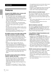
...E L/R DIRECTION SET button Hold down the RESET button and press button 1 to perform panning and tilting. Press it with the same Remote Commander. Press the T (telephoto) side of the button to zoom in the memory of the main menu. B FOCUS buttons Used for focus adjustment. The camera number can be set different camera numbers. Overview Remote Commander (supplied) 1 2 3 4 5 POWER CAMERA SELECT 1 2 3 AUTO FOCUS MANUAL FAR NEAR DATA SCREEN BACK LIGHT STD REV 123 456 PRESET RESET POSITION PAN-TILT HOME PAN-TILT RESET SLOW ZOOM FAST TT W L/R DIRECTION SET W RM...
...E L/R DIRECTION SET button Hold down the RESET button and press button 1 to perform panning and tilting. Press it with the same Remote Commander. Press the T (telephoto) side of the button to zoom in the memory of the main menu. B FOCUS buttons Used for focus adjustment. The camera number can be set different camera numbers. Overview Remote Commander (supplied) 1 2 3 4 5 POWER CAMERA SELECT 1 2 3 AUTO FOCUS MANUAL FAR NEAR DATA SCREEN BACK LIGHT STD REV 123 456 PRESET RESET POSITION PAN-TILT HOME PAN-TILT RESET SLOW ZOOM FAST TT W L/R DIRECTION SET W RM...
Operating Instructions
Page 21
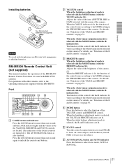
... the control with BRC-Z700 cameras. When the BRIGHT indicator is selected, the R and B indicators are lit. For details, see "Functions of the R and B controls" on page 50. When the white balance adjustment mode is lit, the function of the camera. Front 890qaqsqd qf 1 2 3 4 5 6 7 VALUE LOCK - + R BRIGHT MODE - + B FOCUS AUTO AUTO MANUAL NEAR FAR ONE PUSH AF RESET PRESET SHIFT L/R DIRECTION POWER PANEL LIGHT BLACK PAN-TILT ONE PUSH LIGHT RESET AWB MENU POSITION...
... the control with BRC-Z700 cameras. When the BRIGHT indicator is selected, the R and B indicators are lit. For details, see "Functions of the R and B controls" on page 50. When the white balance adjustment mode is lit, the function of the camera. Front 890qaqsqd qf 1 2 3 4 5 6 7 VALUE LOCK - + R BRIGHT MODE - + B FOCUS AUTO AUTO MANUAL NEAR FAR ONE PUSH AF RESET PRESET SHIFT L/R DIRECTION POWER PANEL LIGHT BLACK PAN-TILT ONE PUSH LIGHT RESET AWB MENU POSITION...

Operating Instructions
Page 22
... pan/tilt speed changes according to the angle of the camera is displayed The joystick is cleared to perform the one of the POSITION buttons. When the menu of the inclination. H RESET button Hold down this button to reset the pan/tilt position of the camera corresponding to ON in standby mode. L PAN-TILT RESET button Press this button and press one -push auto focus function. P SHIFT button and indicators Hold down this button and press the POWER button...
... pan/tilt speed changes according to the angle of the camera is displayed The joystick is cleared to perform the one of the POSITION buttons. When the menu of the inclination. H RESET button Hold down this button to reset the pan/tilt position of the camera corresponding to ON in standby mode. L PAN-TILT RESET button Press this button and press one -push auto focus function. P SHIFT button and indicators Hold down this button and press the POWER button...
Operating Instructions
Page 23
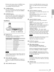
... down this switch to turn on/off the power of the camera corresponding to the pressed button. The selected CAMERA button lights in the memory. T POSITION buttons You can store the various camera settings such as the pan, tilt and zoom positions to the memory of the camera corresponding to the camera address selected with the connected switcher lights. Rear/Bottom MODE RS-232C VISCA RS-422 TALLY/CONTACT ! Switch position 0 1 2 3 4 5 6 7 Camera mode Automatically selected (default) BRC-300...
... down this switch to turn on/off the power of the camera corresponding to the pressed button. The selected CAMERA button lights in the memory. T POSITION buttons You can store the various camera settings such as the pan, tilt and zoom positions to the memory of the camera corresponding to the camera address selected with the connected switcher lights. Rear/Bottom MODE RS-232C VISCA RS-422 TALLY/CONTACT ! Switch position 0 1 2 3 4 5 6 7 Camera mode Automatically selected (default) BRC-300...

Operating Instructions
Page 28
... You can change various settings, such as shooting conditions and system setup of the camera, while observing menus displayed on the RM- 28 About On-Screen Menus Note You cannot perform pan/tilt and zoom operations while the menu is inserted.) PAGE1 >EXPOSURE COLOR PICTURE FOCUS PAN TILT ZOOM SYSTEM VIDEO OUT SD-SDI 1 Cursor Selects a setting menu. Pressing the DATA SCREEN button on the Remote Commander or the MENU button on a connected monitor. This section...
... You can change various settings, such as shooting conditions and system setup of the camera, while observing menus displayed on the RM- 28 About On-Screen Menus Note You cannot perform pan/tilt and zoom operations while the menu is inserted.) PAGE1 >EXPOSURE COLOR PICTURE FOCUS PAN TILT ZOOM SYSTEM VIDEO OUT SD-SDI 1 Cursor Selects a setting menu. Pressing the DATA SCREEN button on the Remote Commander or the MENU button on a connected monitor. This section...

Operating Instructions
Page 29
... set value, select the setting item using the RM-BR300 Remote Control Unit (not supplied). To change a set values are displayed. PAGE1 >EXPOSURE COLOR PICTURE FOCUS PAN TILT ZOOM SYSTEM VIDEO OUT SD-SDI To display PAGE2 of the main menu appears. For details on page 73. 1 POWER CAMERA SELECT 2 1 FOCUS 3 MANUAL NEAR BACK LIGHT FAR AUTO DATA SCREEN 3 REV 2 6 STD RESET 1 4 5 PRESET POSITIOPNAN-TILT HOME 2,4 SLOW 5 ZOOM PARNE-TSIELTT FAST T T W DIREL/CRTION SET 3 W RM-EV100 1 Press the DATA SCREEN button. For the default...
... set value, select the setting item using the RM-BR300 Remote Control Unit (not supplied). To change a set values are displayed. PAGE1 >EXPOSURE COLOR PICTURE FOCUS PAN TILT ZOOM SYSTEM VIDEO OUT SD-SDI To display PAGE2 of the main menu appears. For details on page 73. 1 POWER CAMERA SELECT 2 1 FOCUS 3 MANUAL NEAR BACK LIGHT FAR AUTO DATA SCREEN 3 REV 2 6 STD RESET 1 4 5 PRESET POSITIOPNAN-TILT HOME 2,4 SLOW 5 ZOOM PARNE-TSIELTT FAST T T W DIREL/CRTION SET 3 W RM-EV100 1 Press the DATA SCREEN button. For the default...

Operating Instructions
Page 30
... are operating the menu using the supplied Remote Commander, you cannot set IR-RECEIVE to be changed by pressing the V or v button. 5 Change the value by pressing the B or b button. Menu Operation Using the RMBR300 Remote Control Unit 1 2,4,5 VALUE LOCK - + R BRIGHT MODE - + B FOCUS AUTO AUTO MANUAL NEAR FAR ONE PUSH AF RESET PRESET SHIFT L/R DIRECTION POWER PANEL LIGHT BLACK PAN-TILT ONE PUSH LIGHT RESET AWB MENU POSITION 12345678 9 10 11 12 13 14 15 16 STD REV CAMERA 1234567 3 1 Press the MENU button for...
... are operating the menu using the supplied Remote Commander, you cannot set IR-RECEIVE to be changed by pressing the V or v button. 5 Change the value by pressing the B or b button. Menu Operation Using the RMBR300 Remote Control Unit 1 2,4,5 VALUE LOCK - + R BRIGHT MODE - + B FOCUS AUTO AUTO MANUAL NEAR FAR ONE PUSH AF RESET PRESET SHIFT L/R DIRECTION POWER PANEL LIGHT BLACK PAN-TILT ONE PUSH LIGHT RESET AWB MENU POSITION 12345678 9 10 11 12 13 14 15 16 STD REV CAMERA 1234567 3 1 Press the MENU button for...

Operating Instructions
Page 38
... menu consists of the BRC-Z700 and BRU-H700 (if connected). 38 STATUS Menu PAGE2: Shows the settings selected with the SYSTEM and FOCUS menus. Adjusting and Setting With Menus Note The SETUP item does not appear when an HD signal of 50i format is used to PAGE6. PAGE4: Shows the settings selected with the COLOR menu. You can switch the pages with the VIDEO OUT menu...
... menu consists of the BRC-Z700 and BRU-H700 (if connected). 38 STATUS Menu PAGE2: Shows the settings selected with the SYSTEM and FOCUS menus. Adjusting and Setting With Menus Note The SETUP item does not appear when an HD signal of 50i format is used to PAGE6. PAGE4: Shows the settings selected with the COLOR menu. You can switch the pages with the VIDEO OUT menu...

Operating Instructions
Page 42
... "Installation" (page 53) and "Connections" (page 61). The power is turned on the screen, press the desired arrow button. POWER CAMERA SELECT 1 2 3 AUTO FOCUS MANUAL FAR NEAR DATA SCREEN BACK LIGHT POWER STANDBY lights Pan/Tilt and Zoom Operation Panning and Tilting STD POWER 1 CAMERA SELECT 2 1 FOCUS 3 MANUAL NEAR BACK LIGHT CAMERA SELECT FAR AUTO DATA SCREEN 3 REV 2 6 STD RESET 1 4 5 PRESET POSITIOPNAN-TILT HOME REV 2 PARNE-TSIELTT PAN-TILT RESET FAST ZOOM T HOME T SLOW W W RM-EV100 DIREL/CRTION SET L/R DIRECTION SET 1 Press the POWER switch...
... "Installation" (page 53) and "Connections" (page 61). The power is turned on the screen, press the desired arrow button. POWER CAMERA SELECT 1 2 3 AUTO FOCUS MANUAL FAR NEAR DATA SCREEN BACK LIGHT POWER STANDBY lights Pan/Tilt and Zoom Operation Panning and Tilting STD POWER 1 CAMERA SELECT 2 1 FOCUS 3 MANUAL NEAR BACK LIGHT CAMERA SELECT FAR AUTO DATA SCREEN 3 REV 2 6 STD RESET 1 4 5 PRESET POSITIOPNAN-TILT HOME REV 2 PARNE-TSIELTT PAN-TILT RESET FAST ZOOM T HOME T SLOW W W RM-EV100 DIREL/CRTION SET L/R DIRECTION SET 1 Press the POWER switch...

Operating Instructions
Page 46
... to the connected cameras as the camera is turned on the Power Operation Using the RM-BR300 Remote Control Unit 1 2 RESET PANEL LIGHT VALUE LOCK - + R BRIGHT MODE - + B FOCUS AUTO AUTO MANUAL NEAR ONE PUSH FAR AF RESET PRESET SHIFT L/R DIRECTION POWER PANEL LIGHT BLACK PAN-TILT ONE PUSH LIGHT RESET AWB MENU POSITION 12345678 9 10 11 12 13 14 15 16 STD REV CAMERA 1234567 POWER CAMERA STANDBY lights. All the POSITION buttons and CAMERA buttons light. The CAMERA button representing the camera whose power you can switch the camera to "0." Otherwise...
... to the connected cameras as the camera is turned on the Power Operation Using the RM-BR300 Remote Control Unit 1 2 RESET PANEL LIGHT VALUE LOCK - + R BRIGHT MODE - + B FOCUS AUTO AUTO MANUAL NEAR ONE PUSH FAR AF RESET PRESET SHIFT L/R DIRECTION POWER PANEL LIGHT BLACK PAN-TILT ONE PUSH LIGHT RESET AWB MENU POSITION 12345678 9 10 11 12 13 14 15 16 STD REV CAMERA 1234567 POWER CAMERA STANDBY lights. All the POSITION buttons and CAMERA buttons light. The CAMERA button representing the camera whose power you can switch the camera to "0." Otherwise...

Operating Instructions
Page 47
...The camera will turn on, performing the pan/tilt reset action automatically. 2 Press the CAMERA button corresponding to the camera you want to operate. 3 Operate the joystick to 7, using the camera address selectors on the Remote Control Unit and check that the CAMERA buttons light. Pan/Tilt and Zoom Operation Panning and Tilting L/R DIRECTION REV 1 STD PAN-TILT RESET VALUE LOCK - + R BRIGHT MODE - + B FOCUS AUTO AUTO MANUAL NEAR FAR ONE PUSH AF RESET PRESET SHIFT L/R DIRECTION POWER PANEL LIGHT BLACK LIGHT PAN-TILT ONE PUSH RESET AWB MENU POSITION 12345678...
...The camera will turn on, performing the pan/tilt reset action automatically. 2 Press the CAMERA button corresponding to the camera you want to operate. 3 Operate the joystick to 7, using the camera address selectors on the Remote Control Unit and check that the CAMERA buttons light. Pan/Tilt and Zoom Operation Panning and Tilting L/R DIRECTION REV 1 STD PAN-TILT RESET VALUE LOCK - + R BRIGHT MODE - + B FOCUS AUTO AUTO MANUAL NEAR FAR ONE PUSH AF RESET PRESET SHIFT L/R DIRECTION POWER PANEL LIGHT BLACK LIGHT PAN-TILT ONE PUSH RESET AWB MENU POSITION 12345678...

Operating Instructions
Page 51
... MODE - + B FOCUS AUTO AUTO MANUAL NEAR FAR ONE PUSH AF RESET PRESET SHIFT L/R DIRECTION POWER PANEL LIGHT BLACK LIGHT PAN-TILT ONE PUSH RESET AWB MENU POSITION 12345678 9 10 11 12 13 14 15 16 STD REV CAMERA 1234567 4 2 1 Press the PAN-TILT RESET button to reset the pan/ tilt position. 2 Press the CAMERA button to select the camera whose settings you release the SHIFT button, the upper indicator lights and the POSITION 1 to 8 buttons can be used SHUTTER Pri IRIS Pri Shutter speed control F-number control...
... MODE - + B FOCUS AUTO AUTO MANUAL NEAR FAR ONE PUSH AF RESET PRESET SHIFT L/R DIRECTION POWER PANEL LIGHT BLACK LIGHT PAN-TILT ONE PUSH RESET AWB MENU POSITION 12345678 9 10 11 12 13 14 15 16 STD REV CAMERA 1234567 4 2 1 Press the PAN-TILT RESET button to reset the pan/ tilt position. 2 Press the CAMERA button to select the camera whose settings you release the SHIFT button, the upper indicator lights and the POSITION 1 to 8 buttons can be used SHUTTER Pri IRIS Pri Shutter speed control F-number control...

Operating Instructions
Page 55
...bracket (A) to the bottom of the camera. Installation on a ceiling (example) 1 Set IMG-FLIP to ON in the SYSTEM menu. 2 Remove the four screws on a shelf, etc. This is required in a high position, entrust the installation to an experienced contractor or installer. • Attach the camera... Notes • The connecting cables cannot be distorted. in a High Position Using the supplied ceiling brackets, wire rope and screws, and the attachment materials (not supplied), you have to ensure that the pan/tilt performance is not strong enough, the camera may be passed through the...
...bracket (A) to the bottom of the camera. Installation on a ceiling (example) 1 Set IMG-FLIP to ON in the SYSTEM menu. 2 Remove the four screws on a shelf, etc. This is required in a high position, entrust the installation to an experienced contractor or installer. • Attach the camera... Notes • The connecting cables cannot be distorted. in a High Position Using the supplied ceiling brackets, wire rope and screws, and the attachment materials (not supplied), you have to ensure that the pan/tilt performance is not strong enough, the camera may be passed through the...

Operating Instructions
Page 71
... turned The supplied AC power adaptor is set to OFF (page 19). Press the CAMERA SELECT button corresponding to the camera. Set camera address selector switch 4 of the BOTTOM switches on the camera (page 43). OFF. Pan, tilt or zoom cannot be operated with the BOTTOM switch on the bottom of the camera is not on the Remote Control Unit (page 23). The communication baud rate setting of the camera to ON. Appendix 71 Troubleshooting monitor connected...
... turned The supplied AC power adaptor is set to OFF (page 19). Press the CAMERA SELECT button corresponding to the camera. Set camera address selector switch 4 of the BOTTOM switches on the camera (page 43). OFF. Pan, tilt or zoom cannot be operated with the BOTTOM switch on the bottom of the camera is not on the Remote Control Unit (page 23). The communication baud rate setting of the camera to ON. Appendix 71 Troubleshooting monitor connected...


