Operating Instructions
Page 1
3-287-510-11 (1) HD 3CMOS Color Video Camera Operating Instructions Printed on recycled paper. Sony Corporation Printed in Japan BRC-Z700 © 2007 Sony Corporation 3287510110
3-287-510-11 (1) HD 3CMOS Color Video Camera Operating Instructions Printed on recycled paper. Sony Corporation Printed in Japan BRC-Z700 © 2007 Sony Corporation 3287510110

Operating Instructions
Page 3
... Simultaneouly to CMOS Image Sensors .... 5 Overview Features 6 System Components 7 Supplied Components and Accessories 7 Optional Products 8 System Configuration 11 Operating a BRC-Z700 Camera Using the Supplied Remote Commander 11 Operating a BRC-Z700 Camera Using the RM- controllable Cameras in Memory - Table of Contents Getting Started Precautions 5 Phenomena Specific to the HDV Video Equipment 17 Location and Function of...
... Simultaneouly to CMOS Image Sensors .... 5 Overview Features 6 System Components 7 Supplied Components and Accessories 7 Optional Products 8 System Configuration 11 Operating a BRC-Z700 Camera Using the Supplied Remote Commander 11 Operating a BRC-Z700 Camera Using the RM- controllable Cameras in Memory - Table of Contents Getting Started Precautions 5 Phenomena Specific to the HDV Video Equipment 17 Location and Function of...

Operating Instructions
Page 4
...with VISCA RS232C Connector 63 Connecting a Device Equipped with Back Lighting 50 Adjusting the White Balance 50 Adjusting the Brightness 50 Storing the Camera Settings in a High Position ........ 55 Connections 61 Connecting to an AC Outlet 61 Connecting the RM-BR300 Remote Control Unit 62 ...Connecting a Monitor, etc. Presetting Feature 51 Storing Camera Settings 51 Setting the Speed of Contents Adjusting the Camera 49 Focusing on a Subject 49 Shooting with VISCA RS422 Connector 64 Connecting a Video Monitor, VTR, etc...
...with VISCA RS232C Connector 63 Connecting a Device Equipped with Back Lighting 50 Adjusting the White Balance 50 Adjusting the Brightness 50 Storing the Camera Settings in a High Position ........ 55 Connections 61 Connecting to an AC Outlet 61 Connecting the RM-BR300 Remote Control Unit 62 ...Connecting a Monitor, etc. Presetting Feature 51 Storing Camera Settings 51 Setting the Speed of Contents Adjusting the Camera 49 Focusing on a Subject 49 Shooting with VISCA RS422 Connector 64 Connecting a Video Monitor, VTR, etc...

Operating Instructions
Page 5
...as originally packed at a high environmental temperature • when you have raised the gain (sensitivity) This symptom may be improved by turning the camera off any mobile phone near heaters) - If abnormal noise occurs, consult with the FLICKER CANCEL function. You are cautioned that may appear in.... In such cases, turn off and then on again. In some cases, such phenomena may not be improved with your Sony dealer. Transportation When transporting the camera, repack it as they may appear jagged or flicker. Note on laser beams Laser beams may be generated on (see page...
...as originally packed at a high environmental temperature • when you have raised the gain (sensitivity) This symptom may be improved by turning the camera off any mobile phone near heaters) - If abnormal noise occurs, consult with the FLICKER CANCEL function. You are cautioned that may appear in.... In such cases, turn off and then on again. In some cases, such phenomena may not be improved with your Sony dealer. Transportation When transporting the camera, repack it as they may appear jagged or flicker. Note on laser beams Laser beams may be generated on (see page...
Operating Instructions
Page 6
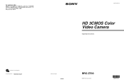
...with the switch at low speed realizes a minimum pan/ tilt speed of 0.22º per second. in down-converted output The camera is enabled. Using the optional 0.8-magnification wide conversion lens allows remote shooting of high-definition images for various shooting situations. • Adoption... use of the BRBK-MF1 HD Optical Multiplex Card, CCFC-M100HG Optical Fiber Cable and BRU-H700 Optical Multiplex Unit, and Sony's unique camera connection technology and optical digital multiplex transmission technology allows a long distance transmission of 38,400 bps. • The optional RM...
...with the switch at low speed realizes a minimum pan/ tilt speed of 0.22º per second. in down-converted output The camera is enabled. Using the optional 0.8-magnification wide conversion lens allows remote shooting of high-definition images for various shooting situations. • Adoption... use of the BRBK-MF1 HD Optical Multiplex Card, CCFC-M100HG Optical Fiber Cable and BRU-H700 Optical Multiplex Unit, and Sony's unique camera connection technology and optical digital multiplex transmission technology allows a long distance transmission of 38,400 bps. • The optional RM...

Operating Instructions
Page 7
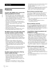
...accessories supplied with an external video sync function to synchronize the camera images on multiple cameras. Tally lamp The tally lamp of optional products are available for the BRCZ700 HD 3CMOS Color Video Camera. This section introduces these optional products as well as standard... equipment. External video sync function The camera is selected at a glance. Camera (1) Overview AC power adaptor MPA-AC1 (Sony) (1) AC power cord (1) USA and Canadian model...
...accessories supplied with an external video sync function to synchronize the camera images on multiple cameras. Tally lamp The tally lamp of optional products are available for the BRCZ700 HD 3CMOS Color Video Camera. This section introduces these optional products as well as standard... equipment. External video sync function The camera is selected at a glance. Camera (1) Overview AC power adaptor MPA-AC1 (Sony) (1) AC power cord (1) USA and Canadian model...

Operating Instructions
Page 8
... power adaptor (1), AC power cord (1), RS-232C connecting cable (3 m) (1), RS-422 connector plug (2) BRBK-MF1 HD Optical Multiplex Card Insert the card into the camera to seven cameras. Ceiling bracket (A) (1) Operating Instructions (1) Optional Products RM-BR300 Remote Control Unit Ceiling bracket (B) (1) Wire rope (1) 8 System Components The joystick of up to allow high...
... power adaptor (1), AC power cord (1), RS-232C connecting cable (3 m) (1), RS-422 connector plug (2) BRBK-MF1 HD Optical Multiplex Card Insert the card into the camera to seven cameras. Ceiling bracket (A) (1) Operating Instructions (1) Optional Products RM-BR300 Remote Control Unit Ceiling bracket (B) (1) Wire rope (1) 8 System Components The joystick of up to allow high...

Operating Instructions
Page 9
... signal of 100 m (328 feet) long. BRBK-HSD1 HD/SD-SDI Output Card Video Switcher (commercially available) Overview Insert the card into the BRC-Z700 camera. Supplied accessories: AC power cord (1), RS-232C connecting cable (3 m) (1), RS-422 connector plug (1) CCFC-M100HG Optical Fiber Cable The lens is... not output from the card. Supplied accessories: extension plug The board allows output of multiple cameras. They cannot be used with the BRU-H700 HD Optical Multiplex Unit. BRU-H700 HD Optical Multiplex Unit It switches the video ...
... signal of 100 m (328 feet) long. BRBK-HSD1 HD/SD-SDI Output Card Video Switcher (commercially available) Overview Insert the card into the BRC-Z700 camera. Supplied accessories: AC power cord (1), RS-232C connecting cable (3 m) (1), RS-422 connector plug (1) CCFC-M100HG Optical Fiber Cable The lens is... not output from the card. Supplied accessories: extension plug The board allows output of multiple cameras. They cannot be used with the BRU-H700 HD Optical Multiplex Unit. BRU-H700 HD Optical Multiplex Unit It switches the video ...

Operating Instructions
Page 10
HFBK-XG1 XGA Interface Board The board allows output of a signal conforming to SMPTE292M serial digital interface standards, or output of an analog video signal (component/RGB). HFBK-TS1 HDV Interface Board The board allows conversion of the video signal from the board. Overview HFBK-HD1 HD Interface Board The board allows output of an HD-SDI signal conforming to the VESA standards (VGA, XGA or WXGA). An audio signal of the HD-SDI signal is not output from the camera and the input audio signal into the signal conforming to the HDV standards. 10 System Components
HFBK-XG1 XGA Interface Board The board allows output of a signal conforming to SMPTE292M serial digital interface standards, or output of an analog video signal (component/RGB). HFBK-TS1 HDV Interface Board The board allows conversion of the video signal from the board. Overview HFBK-HD1 HD Interface Board The board allows output of an HD-SDI signal conforming to the VESA standards (VGA, XGA or WXGA). An audio signal of the HD-SDI signal is not output from the camera and the input audio signal into the signal conforming to the HDV standards. 10 System Components
Operating Instructions
Page 11
Overview Remote Commander (supplied) Video signal Signal flow Operating a BRC-Z700 Camera Using the RM-BR300 Remote Control Unit This system allows you : To operate the camera readily from a short distance System configuration BRC-Z700 HD video monitor, VTR, etc. Operating a BRC-Z700 Camera Using the Supplied Remote Commander This system allows you : To perform pan/tilt and zoom operations...
Overview Remote Commander (supplied) Video signal Signal flow Operating a BRC-Z700 Camera Using the RM-BR300 Remote Control Unit This system allows you : To operate the camera readily from a short distance System configuration BRC-Z700 HD video monitor, VTR, etc. Operating a BRC-Z700 Camera Using the Supplied Remote Commander This system allows you : To perform pan/tilt and zoom operations...

Operating Instructions
Page 12
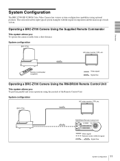
Overview Operating Multiple BRC-Z700 Cameras Using the RM-BR300 Remote Control Unit This system allows you: • To operate up to seven cameras remotely using a single Remote Control Unit • To perform pan/tilt and zoom operations using the joystick System configuration BRC-Z700 HD video monitor, VTR, etc. BRC-Z700 BRC-Z700 Video switcher RM-BR300 Remote Control Unit Video signal Remote control (VISCA) signal Tally/contact signal , Signal flow 12 System Configuration
Overview Operating Multiple BRC-Z700 Cameras Using the RM-BR300 Remote Control Unit This system allows you: • To operate up to seven cameras remotely using a single Remote Control Unit • To perform pan/tilt and zoom operations using the joystick System configuration BRC-Z700 HD video monitor, VTR, etc. BRC-Z700 BRC-Z700 Video switcher RM-BR300 Remote Control Unit Video signal Remote control (VISCA) signal Tally/contact signal , Signal flow 12 System Configuration

Operating Instructions
Page 13
...the BRU-H700. • When the BRBK-MF1 HD Optical Multiplex Card is connected to the BRBK-MF1 HD Optical Multiplex Card inserted into the BRC-Z700 camera, the EXT SYNC IN connector, VISCA RS-232C IN/OUT connectors and VISCA RS-422 connector on the rear of the... disabled. Use the connectors and switches on the bottom of the BRU-H700 HD Optical Multiplex Unit. • The BRC-Z700 camera does not operate if nothing is inserted into the camera. BRC-Z700 CCFC-M100HG Optical Fiber Cable BRBK-MF1 HD Optical Multiplex Card BRU-H700 Optical Multiplex Unit Video signal Remote control (VISCA) ...
...the BRU-H700. • When the BRBK-MF1 HD Optical Multiplex Card is connected to the BRBK-MF1 HD Optical Multiplex Card inserted into the BRC-Z700 camera, the EXT SYNC IN connector, VISCA RS-232C IN/OUT connectors and VISCA RS-422 connector on the rear of the... disabled. Use the connectors and switches on the bottom of the BRU-H700 HD Optical Multiplex Unit. • The BRC-Z700 camera does not operate if nothing is inserted into the camera. BRC-Z700 CCFC-M100HG Optical Fiber Cable BRBK-MF1 HD Optical Multiplex Card BRU-H700 Optical Multiplex Unit Video signal Remote control (VISCA) ...

Operating Instructions
Page 14
... transmit the video signal and control signal of the cameras to a distant place using the Optical Fiber Cable System configuration BRC-Z700 BRU-H700 Optical CCFC-M100HG Multiplex Unit Optical Fiber Cable HD video monitor, VTR, etc. BRC-Z700 BRBK-MF1 HD Optical Multiplex Card BRC-Z700 CCFC-M100HG BRBK-MF1 BRU-H700 Video switcher CCFC-M100HG...
... transmit the video signal and control signal of the cameras to a distant place using the Optical Fiber Cable System configuration BRC-Z700 BRU-H700 Optical CCFC-M100HG Multiplex Unit Optical Fiber Cable HD video monitor, VTR, etc. BRC-Z700 BRBK-MF1 HD Optical Multiplex Card BRC-Z700 CCFC-M100HG BRBK-MF1 BRU-H700 Video switcher CCFC-M100HG...

Operating Instructions
Page 15
... Optical Multiplex Unit Video switcher RM-BR300 Remote Control Unit 15 System Configuration Overview Using BRC-Z700 Cameras and VISCA-controllable Cameras in the Same System This system allows you: • To operate up to seven cameras supporting the VISCA protocol such as EVI-D30/D30P, EVI-D70/D70P, EVI-D100.../ D100P, EVI-HD1, BRC-H700 and BRC-300/300P remotely using a single RM-BR300 Remote Control Unit • To perform pan/tilt and zoom operations using the joystick • To control the BRC-Z700 cameras remotely from a distance up to 1,000 m (3,281 feet) ...
... Optical Multiplex Unit Video switcher RM-BR300 Remote Control Unit 15 System Configuration Overview Using BRC-Z700 Cameras and VISCA-controllable Cameras in the Same System This system allows you: • To operate up to seven cameras supporting the VISCA protocol such as EVI-D30/D30P, EVI-D70/D70P, EVI-D100.../ D100P, EVI-HD1, BRC-H700 and BRC-300/300P remotely using a single RM-BR300 Remote Control Unit • To perform pan/tilt and zoom operations using the joystick • To control the BRC-Z700 cameras remotely from a distance up to 1,000 m (3,281 feet) ...

Operating Instructions
Page 16
... using the joystick • To transmit the video signal and control signal of the camera, and the audio signal input to the BRBK-MF1 Optical Multiplex Card to a distant place using the Optical Fiber Cable System configuration BRC-Z700 Microphone Microphone amplifier HD video monitor Speakers Audio amplifier BRBK-MF1 HD Optical Multiplex...
... using the joystick • To transmit the video signal and control signal of the camera, and the audio signal input to the BRBK-MF1 Optical Multiplex Card to a distant place using the Optical Fiber Cable System configuration BRC-Z700 Microphone Microphone amplifier HD video monitor Speakers Audio amplifier BRBK-MF1 HD Optical Multiplex...

Operating Instructions
Page 17
...TS1 HDV Interface Board to Input Audio and Video Signals Simultaneouly to the HDV Video Equipment This system allows you: • To operate the camera remotely from a distance up to 1,000m (3,281 feet) • To perform pan/tilt and zoom operations using the joystick • To...uncomfortable with the delay, output the video signal via the HFBK-TS1 HDV Interface Board simultaneously to the HDV video equipment System configuration BRC-Z700 Microphone BRBK-MF1 HD Optical Multiplex Card Microphone amplifier HD video monitor HDV VTR equipped with HDV video equipment connected to the i.LINK...
...TS1 HDV Interface Board to Input Audio and Video Signals Simultaneouly to the HDV Video Equipment This system allows you: • To operate the camera remotely from a distance up to 1,000m (3,281 feet) • To perform pan/tilt and zoom operations using the joystick • To...uncomfortable with the delay, output the video signal via the HFBK-TS1 HDV Interface Board simultaneously to the HDV video equipment System configuration BRC-Z700 Microphone BRBK-MF1 HD Optical Multiplex Card Microphone amplifier HD video monitor HDV VTR equipped with HDV video equipment connected to the i.LINK...

Operating Instructions
Page 18
... connection to the VISCA RS-422 connector, see "Using the VISCA RS-422 Connector Plug" on the camera. M VISCA RS-232C IN connector Connect to turn them over and attach upside down if necessary. D SONY and HD nameplates Pull them out to the RM-BR300 Remote Control Unit (not supplied). B Tally lamp... Lights in red when a VISCA tally command is received or the camera is connected to the EXT SYNC IN connector on page 90...
... connection to the VISCA RS-422 connector, see "Using the VISCA RS-422 Connector Plug" on the camera. M VISCA RS-232C IN connector Connect to turn them over and attach upside down if necessary. D SONY and HD nameplates Pull them out to the RM-BR300 Remote Control Unit (not supplied). B Tally lamp... Lights in red when a VISCA tally command is received or the camera is connected to the EXT SYNC IN connector on page 90...

Operating Instructions
Page 19
..., RS232C/RS-422 selection, baud rate selection, remote control signal output on the RMBR300 Remote Control Unit. U Tripod screw holes (1/4-20UNC) When you install the camera to a tripod, secure the tripod to "0". Setting of the BOTTOM switches 1 O 2 N 3 4 1 O 2 N 3 4 1 2 3 4 5 1 ...Switch 1 (59.94i/50i signal format selector) Set to ON for output of 50i signal format, or OFF for output of the next camera in a High Position" on a shelf, etc. Bottom w; V BOTTOM switches Used for 9600bps. 4 Switch 4 (Infrared signal output switch) Set to ON to enable an ...
..., RS232C/RS-422 selection, baud rate selection, remote control signal output on the RMBR300 Remote Control Unit. U Tripod screw holes (1/4-20UNC) When you install the camera to a tripod, secure the tripod to "0". Setting of the BOTTOM switches 1 O 2 N 3 4 1 O 2 N 3 4 1 2 3 4 5 1 ...Switch 1 (59.94i/50i signal format selector) Set to ON for output of 50i signal format, or OFF for output of the next camera in a High Position" on a shelf, etc. Bottom w; V BOTTOM switches Used for 9600bps. 4 Switch 4 (Infrared signal output switch) Set to ON to enable an ...

Operating Instructions
Page 20
... on the rear of the pressed number button. J ZOOM buttons Use the SLOW button to zoom slowly, and the FAST button to store the current camera direction, zooming, focus adjustment and backlight compensation in , and the W (wide angle) side to reset the pan/tilt position. E L/R DIRECTION SET button Hold...to zoom quickly. F POWER switch Press this button to zoom out. 20 Location and Function of the button to zoom in the memory of the camera. To erase the memory contents, hold down this button once to display PAGE1 and twice to perform panning and tilting. I PAN-TILT RESET button ...
... on the rear of the pressed number button. J ZOOM buttons Use the SLOW button to zoom slowly, and the FAST button to store the current camera direction, zooming, focus adjustment and backlight compensation in , and the W (wide angle) side to reset the pan/tilt position. E L/R DIRECTION SET button Hold...to zoom quickly. F POWER switch Press this button to zoom out. 20 Location and Function of the button to zoom in the memory of the camera. To erase the memory contents, hold down this button once to display PAGE1 and twice to perform panning and tilting. I PAN-TILT RESET button ...
Operating Instructions
Page 21
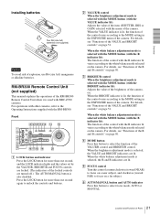
... page 50. When the white balance adjustment mode is lit, the function of the control varies according to the white balance mode selected on the camera. Overview Installing batteries Two R6 (size AA) batteries (not supplied) Caution To avoid risk of the R and B controls" on page 50. Front 890qaqsqd qf 1... and BRIGHT/B control. When the VALUE indicator is used with the menu of the item (SHUTTER, IRIS or GAIN) selected with BRC-Z700 cameras. When the white balance adjustment mode is selected, the VALUE and BRIGHT indicators are turned off.) The AUTO/MANUAL button is selected ...
... page 50. When the white balance adjustment mode is lit, the function of the control varies according to the white balance mode selected on the camera. Overview Installing batteries Two R6 (size AA) batteries (not supplied) Caution To avoid risk of the R and B controls" on page 50. Front 890qaqsqd qf 1... and BRIGHT/B control. When the VALUE indicator is used with the menu of the item (SHUTTER, IRIS or GAIN) selected with BRC-Z700 cameras. When the white balance adjustment mode is selected, the VALUE and BRIGHT indicators are turned off.) The AUTO/MANUAL button is selected ...


