
Service Manual
Page 2
... Since the melting point of lead-free solder is about 220°C, which may corrode easily. Turn ON/OFF the soldering iron power frequently. XE-A203U/XE-A203A LEAD-FREE SOLDER Example: 5mm Lead-Free Solder composition code (Refer to separate the soldering iron from the PWB when completion of soldering is discolored...
... Since the melting point of lead-free solder is about 220°C, which may corrode easily. Turn ON/OFF the soldering iron power frequently. XE-A203U/XE-A203A LEAD-FREE SOLDER Example: 5mm Lead-Free Solder composition code (Refer to separate the soldering iron from the PWB when completion of soldering is discolored...
Service Manual
Page 3
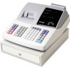
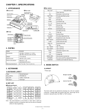
... spool Print roller arm Print roller release lever Inner cover Rear view Customer display (Pop-up type) Power cord Mode switch SD card slot USB port Paper roll cradle Paper positioning guides 2. MODE SWITCH 3. XE-A203U/XE-A203A SPECIFICATIONS - 1 - RATING Model Dimensions Weight Power source Power consumption Working temperature XE-A203 13.8...Tax 2 SHIFT AUTO CHK CH MDSE SBTL #/TM/SBTL CA/AT/NS DESCRIPTION Paper feed key Received-on account key Receipt print/Paid-out key Void key Escape key Conversion key Percent 1and 2 key Refund key Discount key Multiplication key Decimal point key...
... spool Print roller arm Print roller release lever Inner cover Rear view Customer display (Pop-up type) Power cord Mode switch SD card slot USB port Paper roll cradle Paper positioning guides 2. MODE SWITCH 3. XE-A203U/XE-A203A SPECIFICATIONS - 1 - RATING Model Dimensions Weight Power source Power consumption Working temperature XE-A203 13.8...Tax 2 SHIFT AUTO CHK CH MDSE SBTL #/TM/SBTL CA/AT/NS DESCRIPTION Paper feed key Received-on account key Receipt print/Paid-out key Void key Escape key Conversion key Percent 1and 2 key Refund key Discount key Multiplication key Decimal point key...
Service Manual
Page 4
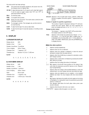
... new ones immediately. : May appear right below the tenth place when power save mode is effective. : Appears when the print roller arm is not locked. : Appears when the paper is under the required level. PGM: To program various items. ... When you have registered ten times, the display will show "0." (2 3 3 ..... 9 3 0 3 1 3 2 ... ) Receipt function status: The indicator "_" appears in the RCPT OFF position when the receipt function is nearly full. MGR: For manager's entries. Number of repeats for an override entry. " " or hour-minute - XE-A203U/XE-A203A SPECIFICATIONS - 2...
... new ones immediately. : May appear right below the tenth place when power save mode is effective. : Appears when the print roller arm is not locked. : Appears when the paper is under the required level. PGM: To program various items. ... When you have registered ten times, the display will show "0." (2 3 3 ..... 9 3 0 3 1 3 2 ... ) Receipt function status: The indicator "_" appears in the RCPT OFF position when the receipt function is nearly full. MGR: For manager's entries. Number of repeats for an override entry. " " or hour-minute - XE-A203U/XE-A203A SPECIFICATIONS - 2...
Service Manual
Page 5
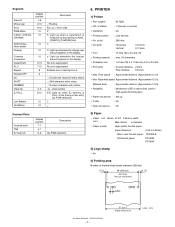
...million lines used to 0.08mm Nihon seisi thermal paper : TF50KS-E Oil thermal paper: PD150R, PD160R 3) Logo stamp • No 4) Printing area Number of key entry (by PGM selection) 6. Segment Amount Minus sign Error PGM Mode CASH, CHECK, CHARGE SUB TOTAL/ short ... 10 dots (W) x 24 dots (H) • Printing capacity : max. 24 characters • Character size : 1.67mm (W) x 4.17mm (H) at the timing of thermal head heater elements 288 dots (4.75) 48 (288 dots) print area (max.24 characters) (4.75) 0.167 XE-A203U/XE-A203A SPECIFICATIONS - 3 - 57.5±0.5 (Paper dimension)...
...million lines used to 0.08mm Nihon seisi thermal paper : TF50KS-E Oil thermal paper: PD150R, PD160R 3) Logo stamp • No 4) Printing area Number of key entry (by PGM selection) 6. Segment Amount Minus sign Error PGM Mode CASH, CHECK, CHARGE SUB TOTAL/ short ... 10 dots (W) x 24 dots (H) • Printing capacity : max. 24 characters • Character size : 1.67mm (W) x 4.17mm (H) at the timing of thermal head heater elements 288 dots (4.75) 48 (288 dots) print area (max.24 characters) (4.75) 0.167 XE-A203U/XE-A203A SPECIFICATIONS - 3 - 57.5±0.5 (Paper dimension)...

Service Manual
Page 6
... SEC SECL Disallowed Allowed - 4B/5C 5B/6C Layout: 4B/5C (U version) 5B/6C (A version) 3) Drawer Lock Key This key locks and unlocks the drawer. XE-A203U/XE-A203A SPECIFICATIONS - 4 - Memory holding time: Approximate 1 year after finalization. And the indicator will not appear.
... SEC SECL Disallowed Allowed - 4B/5C 5B/6C Layout: 4B/5C (U version) 5B/6C (A version) 3) Drawer Lock Key This key locks and unlocks the drawer. XE-A203U/XE-A203A SPECIFICATIONS - 4 - Memory holding time: Approximate 1 year after finalization. And the indicator will not appear.
Service Manual
Page 7
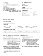
...of "F".) "L 12.34": No battery. ("L" indicate instead of "POWER ON" after the "POWER OFF". 10. OPTIONS 1. SUPPLIES NO NAME 1 Thermal roll paper 4. PROGRAM RESETTING (INITIALIZATION) This resetting resumes the initial program without the memory back up battery. 3) Wait over 1 muinite for discharging.... TOOLS NO NAME 1 USB Cable PARTS CODE TPAPR6656RC05 PARTS CODE PRICERANK BA DESCRIPTION 5 ROLLS/PACK PRICE RANK DESCRIPTION CHAPTER 3. XE-A203U/XE-A203A OPTIONS - 5 - SERVICE OPTIONS (NONE) 3. Note: In case power failure occurs when the machine has no battery attached...
...of "F".) "L 12.34": No battery. ("L" indicate instead of "POWER ON" after the "POWER OFF". 10. OPTIONS 1. SUPPLIES NO NAME 1 Thermal roll paper 4. PROGRAM RESETTING (INITIALIZATION) This resetting resumes the initial program without the memory back up battery. 3) Wait over 1 muinite for discharging.... TOOLS NO NAME 1 USB Cable PARTS CODE TPAPR6656RC05 PARTS CODE PRICERANK BA DESCRIPTION 5 ROLLS/PACK PRICE RANK DESCRIPTION CHAPTER 3. XE-A203U/XE-A203A OPTIONS - 5 - SERVICE OPTIONS (NONE) 3. Note: In case power failure occurs when the machine has no battery attached...
Service Manual
Page 8
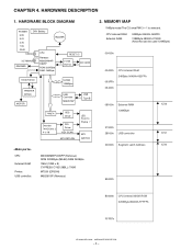
... 08000h External RAM 128KByte /CS2 27000h 28000h USB controller 30000h Segment Latch Address /CS1 /CS0 80000h B0000h CPU internal MASK ROM 320KByte B0000h-FFFFFh FFFFFh XE-A203U/XE-A203A HARDWARE DESCRIPTION - 6 - CHAPTER 4. HARDWARE DESCRIPTION 1. MEMORY MAP 1MByte mode/The CS area PM13 = 1 is selected. HARDWARE BLOCK DIAGRAM POWER DRY Battery 5.8V 5.0V BUZZER...
... 08000h External RAM 128KByte /CS2 27000h 28000h USB controller 30000h Segment Latch Address /CS1 /CS0 80000h B0000h CPU internal MASK ROM 320KByte B0000h-FFFFFh FFFFFh XE-A203U/XE-A203A HARDWARE DESCRIPTION - 6 - CHAPTER 4. HARDWARE DESCRIPTION 1. MEMORY MAP 1MByte mode/The CS area PM13 = 1 is selected. HARDWARE BLOCK DIAGRAM POWER DRY Battery 5.8V 5.0V BUZZER...
Service Manual
Page 9
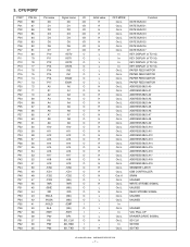
... CONTROLLER SRAM UNUSED WRITE STROBE SIGNAL UNUSED READ STROBE SIGNAL UNUSED UNUSED UNUSED VCC PULL UP DRAWER DRIVE SIGNAL SD CLK SD RXD SD TXD XE-A203U/XE-A203A HARDWARE DESCRIPTION - 7 - 3.
... CONTROLLER SRAM UNUSED WRITE STROBE SIGNAL UNUSED READ STROBE SIGNAL UNUSED UNUSED UNUSED VCC PULL UP DRAWER DRIVE SIGNAL SD CLK SD RXD SD TXD XE-A203U/XE-A203A HARDWARE DESCRIPTION - 7 - 3.
Service Manual
Page 10
...: L / BOOT: H RESET CLOCK CONNECTED TO GND CLOCK CONNECTED TO VDD CONNECTED TO VDD CONNECTED TO GND CONNECTED TO GND CONNECTED TO VDD CONNECTED TO VDD XE-A203U/XE-A203A HARDWARE DESCRIPTION - 8 -
...: L / BOOT: H RESET CLOCK CONNECTED TO GND CLOCK CONNECTED TO VDD CONNECTED TO VDD CONNECTED TO GND CONNECTED TO GND CONNECTED TO VDD CONNECTED TO VDD XE-A203U/XE-A203A HARDWARE DESCRIPTION - 8 -
Service Manual
Page 11
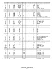
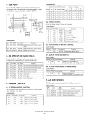
...PORT Use signal Function 89 P107 STRB1# Printer STB1# 94 P102 STRB2# Printer STB2# 30 P70 DAT Printer print data 28 P72 PCLK Printer forwarding clock 90 P106 LATCH# Printer data latch 91 P105 VPON Printer head motor power... 24 P76 (TA3OUT) /REUSB M66291 Reset control 5. PRINTER CONTROL 6-1. The M66291 is made in the SPI mode. SD CARD I/F (XE-A203U ONLY) One port for USB Port (Slave) is provided as a standard provision. CPU A0 A1-A6 D0-D7 /CS1 /RD... Printer head voltage monitor 93 AN3/P103 VBAT Battery voltage monitor XE-A203U/XE-A203A HARDWARE DESCRIPTION - 9 - 4.
...PORT Use signal Function 89 P107 STRB1# Printer STB1# 94 P102 STRB2# Printer STB2# 30 P70 DAT Printer print data 28 P72 PCLK Printer forwarding clock 90 P106 LATCH# Printer data latch 91 P105 VPON Printer head motor power... 24 P76 (TA3OUT) /REUSB M66291 Reset control 5. PRINTER CONTROL 6-1. The M66291 is made in the SPI mode. SD CARD I/F (XE-A203U ONLY) One port for USB Port (Slave) is provided as a standard provision. CPU A0 A1-A6 D0-D7 /CS1 /RD... Printer head voltage monitor 93 AN3/P103 VBAT Battery voltage monitor XE-A203U/XE-A203A HARDWARE DESCRIPTION - 9 - 4.
Service Manual
Page 12
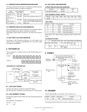
... AN3 pin. For 174 (3.40V) or less, it is as NO BATTERY. 8. CPU PORT AND REGISTER Function Address R/W LED Segment Signal 30000h W Address Bit7 Bit6 Bit5 Bit4 Bit3 Bit2 Bit1 Bit0 30000h dp.... Data~Segment correspondence D0~D6 3 a~g D7 3 DP The XE-A203U/A203A is judged as follow: 55ms (max) 50ms (min) XE-A203U/XE-A203A HARDWARE DESCRIPTION - 10 - PORT 80 P10 79 P11 78 P12...10°C ~ Less than 0°C 869~928 Print in the conduction time at 0°C. 0°C ~ Less than 70°C 232~868 Print in A/D conversion value. 7-3. BATTERY VOLTAGE MONITOR The...
... AN3 pin. For 174 (3.40V) or less, it is as NO BATTERY. 8. CPU PORT AND REGISTER Function Address R/W LED Segment Signal 30000h W Address Bit7 Bit6 Bit5 Bit4 Bit3 Bit2 Bit1 Bit0 30000h dp.... Data~Segment correspondence D0~D6 3 a~g D7 3 DP The XE-A203U/A203A is judged as follow: 55ms (max) 50ms (min) XE-A203U/XE-A203A HARDWARE DESCRIPTION - 10 - PORT 80 P10 79 P11 78 P12...10°C ~ Less than 0°C 869~928 Print in the conduction time at 0°C. 0°C ~ Less than 70°C 232~868 Print in A/D conversion value. 7-3. BATTERY VOLTAGE MONITOR The...
Service Manual
Page 13
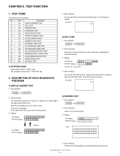
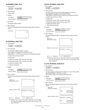
...RCPT/PO 2 Test procedure The decimal point will shift in steps of testing The test will automatically be terminated after the printer prints. NO. Code Description 1) 100 DISPLAY BUZZER TEST 2) 101 KEY CODE 3) 102 PRINTER TEST 4) 104 KEYBOARD TEST 5) 105...position: "PGM" mode Key operation: Above code + "RCPT/PO" key 2. XE-A203U/XE-A203A TEST FUNCTION - 11 - TEST ITEMS The test items are printed. 3 Display OP display: 102 POPUP display: Print: ZZZZZZZZZZZZZZZZZZZZZZZZ ZZZZZZZZZZZZZZZZZZZZZZZZ ZZZZZZZZZZZZZZZZZZZZZZZZ 4 End of 1 digit from the lower digit to a ...
...RCPT/PO 2 Test procedure The decimal point will shift in steps of testing The test will automatically be terminated after the printer prints. NO. Code Description 1) 100 DISPLAY BUZZER TEST 2) 101 KEY CODE 3) 102 PRINTER TEST 4) 104 KEYBOARD TEST 5) 105...position: "PGM" mode Key operation: Above code + "RCPT/PO" key 2. XE-A203U/XE-A203A TEST FUNCTION - 11 - TEST ITEMS The test items are printed. 3 Display OP display: 102 POPUP display: Print: ZZZZZZZZZZZZZZZZZZZZZZZZ ZZZZZZZZZZZZZZZZZZZZZZZZ ZZZZZZZZZZZZZZZZZZZZZZZZ 4 End of 1 digit from the lower digit to a ...
Service Manual
Page 14
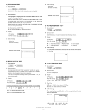
... made . m m s s (*) hh = hour mm = min ss = sec 4 Check that the positions are printed and the test mode will terminated. End print: yymmdd-hhmmss 107 (*) yy = year mm = month dd = day hh = hour mm = min ss = sec XE-A203U/XE-A203A TEST FUNCTION - 12 - Check that A) Check "-" blinks at an interval of 500ms. B) Check the clock...
... made . m m s s (*) hh = hour mm = min ss = sec 4 Check that the positions are printed and the test mode will terminated. End print: yymmdd-hhmmss 107 (*) yy = year mm = month dd = day hh = hour mm = min ss = sec XE-A203U/XE-A203A TEST FUNCTION - 12 - Check that A) Check "-" blinks at an interval of 500ms. B) Check the clock...
Service Manual
Page 15
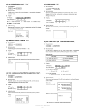
... the address where the error has occurred in the test area is stored. When an error occurs: RAM ERROR X *****h 120 ROM XE-A203U/XE-A203A TEST FUNCTION - 13 - FFFFFH) is restored. 3 Display OP display: 121 POPUP display: 4 End of testing The test will automatically... be 10H. 3 Display OP display: 140 POPUP display: 4 End of testing. The lower two digits of the checksum should be terminated and the printer prints...
... the address where the error has occurred in the test area is stored. When an error occurs: RAM ERROR X *****h 120 ROM XE-A203U/XE-A203A TEST FUNCTION - 13 - FFFFFH) is restored. 3 Display OP display: 121 POPUP display: 4 End of testing The test will automatically... be 10H. 3 Display OP display: 140 POPUP display: 4 End of testing. The lower two digits of the checksum should be terminated and the printer prints...
Service Manual
Page 16
... VOLTAGE 160 *** *** *** 15) SLEEP MODE TEST 1 Key operation 550 RCPT/PO 2 Test procedure Check to the error print.) XE-A203U/XE-A203A TEST FUNCTION - 14 - POPUP display: 4 End of testing When any key is pressed, the SD card register is read error 3 Display OP display: 620 POPUP display: X-Y X-Y (*) X = SD card detection 1 SD card YES 0 : SD...
... VOLTAGE 160 *** *** *** 15) SLEEP MODE TEST 1 Key operation 550 RCPT/PO 2 Test procedure Check to the error print.) XE-A203U/XE-A203A TEST FUNCTION - 14 - POPUP display: 4 End of testing When any key is pressed, the SD card register is read error 3 Display OP display: 620 POPUP display: X-Y X-Y (*) X = SD card detection 1 SD card YES 0 : SD...

Service Manual
Page 17
CIRCUIT DIAGRAM AND PWB LAYOUT ■ MAIN PWB 1/4 XE-A203U/XE-A203A CIRCUIT DIAGRAM AND PWB LAYOUT - 15 - CPU CIRCUIT VCC D ... 3 2 C13 2 P96 2 P95 1 1000pF 2 2 P94 P93 VDD 2 P92 2 P91 2 P90 R58 1K /RESUSB 2 10K 10K R50 R42 XE-A20W ONLY DAT 2 10K CLK 2 D1 R40 B +BZ1 R52 PIEZO BZ 10K D0 D1 D2 D3 D4 D5 D6 D7 2 3 4 5 A0 ...C21 27pF 32.768KHz 1 2 3 /DREQUSB /INTUSB X3 MOTOR /POFF 2 3 VCC 1 1SS133 VCC3 D0 D1 C24 D2 D3 D4 0.1uF D5 D6 D7 10K R40 XE-A203U/A ONLY 1 2 3 4 5 6 7 8 9 10 11 2 1 VDD + C17 C16 0.1uF IC7 A0 2 A1 3 A2 4 A3 5 A4 6...
CIRCUIT DIAGRAM AND PWB LAYOUT ■ MAIN PWB 1/4 XE-A203U/XE-A203A CIRCUIT DIAGRAM AND PWB LAYOUT - 15 - CPU CIRCUIT VCC D ... 3 2 C13 2 P96 2 P95 1 1000pF 2 2 P94 P93 VDD 2 P92 2 P91 2 P90 R58 1K /RESUSB 2 10K 10K R50 R42 XE-A20W ONLY DAT 2 10K CLK 2 D1 R40 B +BZ1 R52 PIEZO BZ 10K D0 D1 D2 D3 D4 D5 D6 D7 2 3 4 5 A0 ...C21 27pF 32.768KHz 1 2 3 /DREQUSB /INTUSB X3 MOTOR /POFF 2 3 VCC 1 1SS133 VCC3 D0 D1 C24 D2 D3 D4 0.1uF D5 D6 D7 10K R40 XE-A203U/A ONLY 1 2 3 4 5 6 7 8 9 10 11 2 1 VDD + C17 C16 0.1uF IC7 A0 2 A1 3 A2 4 A3 5 A4 6...

Service Manual
Page 18
... 56KF 8 3 + 2 - 4 1 IC8A BA10393 1 R75 5.1KF VO 1,3 TCOFF 3 4 3 VO 2,3 8 5 + 7 6 - 4 IC8B BA10393 2 1 2/4 VP NOT INSTALL C28 0.1uF CN4 1 2 EH-2A 2 1 MOTOR R76 1 1K Q1 2SD2212 D MOTOR 3 XE-A203U/XE-A203A CIRCUIT DIAGRAM AND PWB LAYOUT - 16 - C 1 1 B A D2 /S4 2 1 S 1 1SS133 G2 D 3 P91 P91 Q2 2SK2731 1 1 PE 1 1 C33 0.1uF KST0 KST1 KST2 KST3 /S7 VCC IC9 1 2 A B VCC...
... 56KF 8 3 + 2 - 4 1 IC8A BA10393 1 R75 5.1KF VO 1,3 TCOFF 3 4 3 VO 2,3 8 5 + 7 6 - 4 IC8B BA10393 2 1 2/4 VP NOT INSTALL C28 0.1uF CN4 1 2 EH-2A 2 1 MOTOR R76 1 1K Q1 2SD2212 D MOTOR 3 XE-A203U/XE-A203A CIRCUIT DIAGRAM AND PWB LAYOUT - 16 - C 1 1 B A D2 /S4 2 1 S 1 1SS133 G2 D 3 P91 P91 Q2 2SK2731 1 1 PE 1 1 C33 0.1uF KST0 KST1 KST2 KST3 /S7 VCC IC9 1 2 A B VCC...

Service Manual
Page 19
XE-A203U/XE-A203A CIRCUIT DIAGRAM AND PWB LAYOUT - 17 - 8 7 6 5 4 3 2 1 POWER CIRCUIT 3/4 F2 Q1:HEAT SINK 3C 3C 4 D5 VP 3.15A IPEAK>12A :100% D CN7 2 C42 3- +1 MYLAR Q5 L1 2 ...
XE-A203U/XE-A203A CIRCUIT DIAGRAM AND PWB LAYOUT - 17 - 8 7 6 5 4 3 2 1 POWER CIRCUIT 3/4 F2 Q1:HEAT SINK 3C 3C 4 D5 VP 3.15A IPEAK>12A :100% D CN7 2 C42 3- +1 MYLAR Q5 L1 2 ...

Service Manual
Page 20
XE-A203U/XE-A203A CIRCUIT DIAGRAM AND PWB LAYOUT - 18 - 8 7 6 5 4 3 SD CARD CIRCUIT S:1pin VCC3 VCC3 D:2,3,4,5pin 3 5 G:6pin 1 2 4 1 14Pin : VCC3 + C66 1 6 7Pin : GND 100uF/50V + C56 D VCC3 2 Q9 HAT1089C ...
XE-A203U/XE-A203A CIRCUIT DIAGRAM AND PWB LAYOUT - 18 - 8 7 6 5 4 3 SD CARD CIRCUIT S:1pin VCC3 VCC3 D:2,3,4,5pin 3 5 G:6pin 1 2 4 1 14Pin : VCC3 + C66 1 6 7Pin : GND 100uF/50V + C56 D VCC3 2 Q9 HAT1089C ...

Service Manual
Page 24
XE-A203U/XE-A203A CIRCUIT DIAGRAM AND PWB LAYOUT - 22 - 8 7 6 5 4 3 2 ■ MODE SWITCH CIRCUIT D SW1 MODE SWITCH 0 GND 000 /VON 00 C GND 1 2 3 4 5 6 7 8 9 10 /S7 /S6 /S5 /S4 /S3 MOR/S2 /S1 /S0 /RESET 12 11 10 9 8 7 6 5 4 3 2 1 B CN1 P:2.0mm HOLE ONLY FOR KEY I/F BOARD 13 A 8 7 6 5 4 3 2 1 1/1 D C B A 1
XE-A203U/XE-A203A CIRCUIT DIAGRAM AND PWB LAYOUT - 22 - 8 7 6 5 4 3 2 ■ MODE SWITCH CIRCUIT D SW1 MODE SWITCH 0 GND 000 /VON 00 C GND 1 2 3 4 5 6 7 8 9 10 /S7 /S6 /S5 /S4 /S3 MOR/S2 /S1 /S0 /RESET 12 11 10 9 8 7 6 5 4 3 2 1 B CN1 P:2.0mm HOLE ONLY FOR KEY I/F BOARD 13 A 8 7 6 5 4 3 2 1 1/1 D C B A 1


