XE-A202 Operation Manual in English and Spanish
Page 7
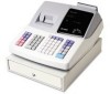
...PGM Manager key (MA) Operator key (OP) OP MA The mode switch has these settings: OFF: This mode locks all register operations. (AC power turns off.) No change occurs to page 39. MGR: For manager's entries. For details, refer to... register data. 3 Mode Switch and Mode Keys The mode switch can be operated by pressing the R key. These keys can ...to take individual clerk X or Z reports, and to toggle receipt state "ON" and "OFF" by inserting one of the two supplied mode keys -
...PGM Manager key (MA) Operator key (OP) OP MA The mode switch has these settings: OFF: This mode locks all register operations. (AC power turns off.) No change occurs to page 39. MGR: For manager's entries. For details, refer to... register data. 3 Mode Switch and Mode Keys The mode switch can be operated by pressing the R key. These keys can ...to take individual clerk X or Z reports, and to toggle receipt state "ON" and "OFF" by inserting one of the two supplied mode keys -

XE-A202 Operation Manual in English and Spanish
Page 69
... a clerk code entry. Make a preset price entry. s Compulsory depression of the key for Service The malfunctions shown in memory.) • Is power supplied to the electrical outlet? • Is the power cord plug out or loosely connected to the electrical outlet? • Is a clerk code assigned to...refer to the table below , labelled "Fault," do not make sense. (2) The display won't be illuminated even when the mode switch is turned to the register? • Is the mode switch set properly at the "REG" position? • Is the paper roll properly installed? • Is there a paper ...
... a clerk code entry. Make a preset price entry. s Compulsory depression of the key for Service The malfunctions shown in memory.) • Is power supplied to the electrical outlet? • Is the power cord plug out or loosely connected to the electrical outlet? • Is a clerk code assigned to...refer to the table below , labelled "Fault," do not make sense. (2) The display won't be illuminated even when the mode switch is turned to the register? • Is the mode switch set properly at the "REG" position? • Is the paper roll properly installed? • Is there a paper ...
XE-A202 Operation Manual in English and Spanish
Page 107
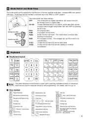
...caused by repairs or attempted repairs performed by anyone other than an authorized servicer. TO OBTAIN SUPPLIES, ACCESSORIES OR PRODUCT INFORMATION, CALL 1-800-BE-SHARP. Correction of defects, in the manner and for any product the exterior of purchase. Additional... time period(s) set forth below nor to any incidental or consequential economic or property damage. Your Product: XE series Electronic Cash Register Warranty Period of purchase to a Sharp Authorized Servicer. Some states do to obtain service: Ship (prepaid) or carry your Product to the servicer...
...caused by repairs or attempted repairs performed by anyone other than an authorized servicer. TO OBTAIN SUPPLIES, ACCESSORIES OR PRODUCT INFORMATION, CALL 1-800-BE-SHARP. Correction of defects, in the manner and for any product the exterior of purchase. Additional... time period(s) set forth below nor to any incidental or consequential economic or property damage. Your Product: XE series Electronic Cash Register Warranty Period of purchase to a Sharp Authorized Servicer. Some states do to obtain service: Ship (prepaid) or carry your Product to the servicer...
Service Manual
Page 2
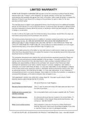
...;C (32°F to 104°F) 3. RATING Weight Dimensions Power source Power consumption Working temperature XE-A202 16.3lb (7.4kg) 13.0 (W) x 16.9 (D) x 11.0 (H) inches (330 (W) x 428 (D) x 280 (H) mm) AC 120V (m10%), 60Hz Stand-by inserting one of the two supplied mode keys - manager (MA) and operator (OP) keys. NUMBER VOID RFND DC SHIFT ESC... Key pitch Key layout Normal keyboard STD/MAX 53 19 (W) x 19 (H) mm Fixed type 2) KEY LIST sKeyboard layout CONV @/FOR • CL RA %1 RCPT /PO %2 - XE-A202U SPECIFICATIONS - 1 - CHAPTER 1.
...;C (32°F to 104°F) 3. RATING Weight Dimensions Power source Power consumption Working temperature XE-A202 16.3lb (7.4kg) 13.0 (W) x 16.9 (D) x 11.0 (H) inches (330 (W) x 428 (D) x 280 (H) mm) AC 120V (m10%), 60Hz Stand-by inserting one of the two supplied mode keys - manager (MA) and operator (OP) keys. NUMBER VOID RFND DC SHIFT ESC... Key pitch Key layout Normal keyboard STD/MAX 53 19 (W) x 19 (H) mm Fixed type 2) KEY LIST sKeyboard layout CONV @/FOR • CL RA %1 RCPT /PO %2 - XE-A202U SPECIFICATIONS - 1 - CHAPTER 1.
Service Manual
Page 6
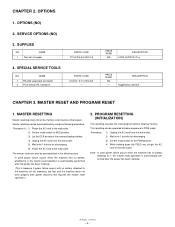
...NO) 2. PRICE RANK BA DESCRIPTION 5 ROLLS/PACK 70 φ PRICE RANK BC - DESCRIPTION Supplied by using the following case. This resetting can be accomplished by software CHAPTER 3. CHAPTER 2. SUPPLIES NO NAME 1 Thermal roll paper PARTS CODE TPAPR6656RC05 4. The master reset can be operated at ...the master reset operation.) 2. PROGRAM RESETTING (INITIALIZATION) This resetting resumes the initial program without clearing memory. XE-A202U OPTIONS - 5 - OPTIONS 1. Note: In case power failure occurs when the machine has no battery attached to the wall outlet....
...NO) 2. PRICE RANK BA DESCRIPTION 5 ROLLS/PACK 70 φ PRICE RANK BC - DESCRIPTION Supplied by using the following case. This resetting can be accomplished by software CHAPTER 3. CHAPTER 2. SUPPLIES NO NAME 1 Thermal roll paper PARTS CODE TPAPR6656RC05 4. The master reset can be operated at ...the master reset operation.) 2. PROGRAM RESETTING (INITIALIZATION) This resetting resumes the initial program without clearing memory. XE-A202U OPTIONS - 5 - OPTIONS 1. Note: In case power failure occurs when the machine has no battery attached to the wall outlet....
Service Manual
Page 7
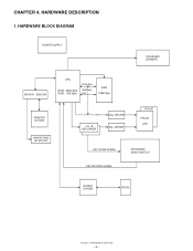
CHAPTER 4. DRIVER , SENSOR CPU ROM : 256K Byte RAM : 20K Byte Data bus Address bus RAM 128K Byte PRINTER M-T53II PAPER TAKE UP MOTOR 4 to 16 DECORDER Seg. HARDWARE BLOCK DIAGRAM POWER SUPPLY STANDARD DRAWER. DRIVER Dig. DRIVER POPUP FRONT LED KEY SCAN SIGNAL KEYBOARD MODE SWITCH KEY RETURN SIGNAL RS232C DRIVER RS232 XE-A202U HARDWARE DESCRIPTION - 6 - HARDWARE DESCRIPTION 1.
CHAPTER 4. DRIVER , SENSOR CPU ROM : 256K Byte RAM : 20K Byte Data bus Address bus RAM 128K Byte PRINTER M-T53II PAPER TAKE UP MOTOR 4 to 16 DECORDER Seg. HARDWARE BLOCK DIAGRAM POWER SUPPLY STANDARD DRAWER. DRIVER Dig. DRIVER POPUP FRONT LED KEY SCAN SIGNAL KEYBOARD MODE SWITCH KEY RETURN SIGNAL RS232C DRIVER RS232 XE-A202U HARDWARE DESCRIPTION - 6 - HARDWARE DESCRIPTION 1.

Service Manual
Page 9
... R15 2.7K C14 1uF/50V R16 9.1KG R19 R17 56K 0 8 3 1 2 IC4A 4 R18 BA10393 3.9K R20 2.7K 5 8 6 4 IC4B BA10393 7 /POFF C15 0.1uF ZD4 MTZJ5.1B P-OFF XE-A202U HARDWARE DESCRIPTION - 8 - If the CPU was not operating properly, the signal does not appear on this line in the "SRV" position, the reset signal... 12MHz R 11 330 XCOUT 10 XCIN X1 32.768KHz C C 18P 27P Two oscillators are connected to reset the hardware. (2) When VDD t 2.8V, a reset signal is supplied from the reset IC. (S80928ANMP) 5.
... R15 2.7K C14 1uF/50V R16 9.1KG R19 R17 56K 0 8 3 1 2 IC4A 4 R18 BA10393 3.9K R20 2.7K 5 8 6 4 IC4B BA10393 7 /POFF C15 0.1uF ZD4 MTZJ5.1B P-OFF XE-A202U HARDWARE DESCRIPTION - 8 - If the CPU was not operating properly, the signal does not appear on this line in the "SRV" position, the reset signal... 12MHz R 11 330 XCOUT 10 XCIN X1 32.768KHz C C 18P 27P Two oscillators are connected to reset the hardware. (2) When VDD t 2.8V, a reset signal is supplied from the reset IC. (S80928ANMP) 5.
Service Manual
Page 10
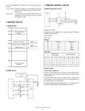
... by two comparators and sent to the shift register synchronizing with the CLOCK (CP) and stored... - 07FFFh /CS2 area 08000h - 27FFFh C0000h FFFFFh CPU internal ROM 256kbytes 2) RAM control Power supply circuit or Dry battery A0-A16 A0-A16 D0-7 /CS2 CPU /RD VDD VCC D0-7 10K...HL H H L H H L 3 HH H H L L H H 4 LH H H H L L H 2) Print circuit Thermal head configuration As shown in the equivalent circuit in the latch register by the LATCH (LA) signal. VLED signal: If the LED/Logic power voltage VLED falls below the specified level, the P-OFF signal is driven at...
... by two comparators and sent to the shift register synchronizing with the CLOCK (CP) and stored... - 07FFFh /CS2 area 08000h - 27FFFh C0000h FFFFFh CPU internal ROM 256kbytes 2) RAM control Power supply circuit or Dry battery A0-A16 A0-A16 D0-7 /CS2 CPU /RD VDD VCC D0-7 10K...HL H H L H H L 3 HH H H L L H H 4 LH H H H L L H 2) Print circuit Thermal head configuration As shown in the equivalent circuit in the latch register by the LATCH (LA) signal. VLED signal: If the LED/Logic power voltage VLED falls below the specified level, the P-OFF signal is driven at...
Service Manual
Page 16
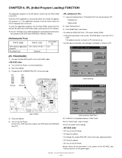
... The application program of PC. SP1 SP1 7) Copy the following files in "PosUtilityTool3" into the hard disk of the XE-A202 is written into the Flash ROM, connect the PC and the XE-A202 with an RS-232C cable, and execute the PC software. *Use a D-Sub 9pin cross cable employed in it, the... the cabinet. 16) Turn on the AC Power. 13) Open the cabinet. 14) Change the Jumper PIN (SP1) to the rear side. Since the CPU supplied as a service part does not include the application program in conventional communication between COM1 and 2. *2 For "Send Type", select "Direct". *3 Do not select "...
... The application program of PC. SP1 SP1 7) Copy the following files in "PosUtilityTool3" into the hard disk of the XE-A202 is written into the Flash ROM, connect the PC and the XE-A202 with an RS-232C cable, and execute the PC software. *Use a D-Sub 9pin cross cable employed in it, the... the cabinet. 16) Turn on the AC Power. 13) Open the cabinet. 14) Change the Jumper PIN (SP1) to the rear side. Since the CPU supplied as a service part does not include the application program in conventional communication between COM1 and 2. *2 For "Send Type", select "Direct". *3 Do not select "...