Operation Manual
Page 6
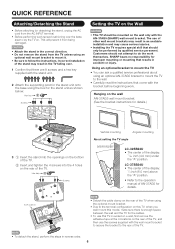
... wall and the TV for details. CAUTION • Attach the stand in accident or injury. Incorrect installation of the display: 11/64 inch (4.0 mm) under the "A" position. SHARP bears no responsibility ...tape at the 4 locations on the rear of the TV. • To detach the stand, perform the steps in an unstable installation and may result in reverse order. 6 LC-37SB24U • The center of the display: 1/4 inch ...9 screws and a hex key supplied with the stand unit. 2 Attach the supporting post for the stand unit onto the base using the box for improper mounting or mounting that come...
... wall and the TV for details. CAUTION • Attach the stand in accident or injury. Incorrect installation of the display: 11/64 inch (4.0 mm) under the "A" position. SHARP bears no responsibility ...tape at the 4 locations on the rear of the TV. • To detach the stand, perform the steps in an unstable installation and may result in reverse order. 6 LC-37SB24U • The center of the display: 1/4 inch ...9 screws and a hex key supplied with the stand unit. 2 Attach the supporting post for the stand unit onto the base using the box for improper mounting or mounting that come...


