
Service Manual
Page 2
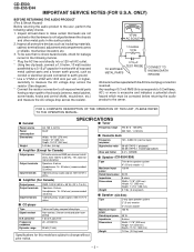
...ratio Wow and flutter 125 - 8,000 Hz (normal tape) 50 dB (TAPE 1, playback) 50 dB (TAPE 2, recording/playback) 0.3 % (WRMS) s Speaker (CD-E500/E55) Type Maximum input power Rated input power Impedance Dimensions Weight Twin-drive speaker system 4" (10 cm) woofer 2 100 W 50 W 8 ohms Width: 7-7/8" (200 ...control shafts, escutcheon, etc.) and measure the AC voltage drop across the resistor (See diagram). * Connect the resistor connection to all protective devices such as conduit or electrical ground connected to 0.2 milliamp. AC.) or more is not lodged between the chassis and other metal ...
...ratio Wow and flutter 125 - 8,000 Hz (normal tape) 50 dB (TAPE 1, playback) 50 dB (TAPE 2, recording/playback) 0.3 % (WRMS) s Speaker (CD-E500/E55) Type Maximum input power Rated input power Impedance Dimensions Weight Twin-drive speaker system 4" (10 cm) woofer 2 100 W 50 W 8 ohms Width: 7-7/8" (200 ...control shafts, escutcheon, etc.) and measure the AC voltage drop across the resistor (See diagram). * Connect the resistor connection to all protective devices such as conduit or electrical ground connected to 0.2 milliamp. AC.) or more is not lodged between the chassis and other metal ...
Service Manual
Page 5
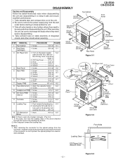
... PWB 1. Socket K2) x2 3. Hook N1) x2 6-5 Block Note 1: How to keep it safe and ensure excellent performance: 1. DISASSEMBLY CD-E500 CD-E55/E44 Caution on the power supply, .. 5-2 open the changer manually. (Fig. 5-3) 1. STEP REMOVAL PROCEDURE FIGURE 1 Top Cabinet 1. Screw D1) x8 5-2 5 ...cassette tape and compact disc out of the connector so as to remove the power supply plug from electrostatic damage. Be sure to protect the optical pickup from the wall outlet before disassembling. 4. Take off nylon bands or wire holders where they were before starting to...
... PWB 1. Socket K2) x2 3. Hook N1) x2 6-5 Block Note 1: How to keep it safe and ensure excellent performance: 1. DISASSEMBLY CD-E500 CD-E55/E44 Caution on the power supply, .. 5-2 open the changer manually. (Fig. 5-3) 1. STEP REMOVAL PROCEDURE FIGURE 1 Top Cabinet 1. Screw D1) x8 5-2 5 ...cassette tape and compact disc out of the connector so as to remove the power supply plug from electrostatic damage. Be sure to protect the optical pickup from the wall outlet before disassembling. 4. Take off nylon bands or wire holders where they were before starting to...
Service Manual
Page 9
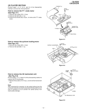
... optical pickup from electrostatic damage. - 9 - Figure 9-2 Holder PWB (C1)x4 ø2.5x10mm Holder CD Mechanism Unit Figure 9-3 Remove the screws (A1) x 2 pcs. 2. Remove the belt (A2) x 1 pc. 3. CD-E500 CD-E55/E44 Loading Tray (A1)x2 ø2.4x3mm (A2)x1 T/T Motor PWB (A3)x2 ø3x10mm ... Figure 9-1 Up/Down Loading Motor (B1)x2 ø2.4x5mm (B2)x1 CD Player Unit How to remove the CD mechanism unit (See Fig. 9-3) Perform steps 1, 2, 3, 10and 13 of the disassembly method to protect the optical pickup from the connector wrap the conductive aluminium foil around the front...
... optical pickup from electrostatic damage. - 9 - Figure 9-2 Holder PWB (C1)x4 ø2.5x10mm Holder CD Mechanism Unit Figure 9-3 Remove the screws (A1) x 2 pcs. 2. Remove the belt (A2) x 1 pc. 3. CD-E500 CD-E55/E44 Loading Tray (A1)x2 ø2.4x3mm (A2)x1 T/T Motor PWB (A3)x2 ø3x10mm ... Figure 9-1 Up/Down Loading Motor (B1)x2 ø2.4x5mm (B2)x1 CD Player Unit How to remove the CD mechanism unit (See Fig. 9-3) Perform steps 1, 2, 3, 10and 13 of the disassembly method to protect the optical pickup from the connector wrap the conductive aluminium foil around the front...
Service Manual
Page 12
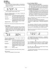
...stored for frequencies to be pressed. (The disc is stored in this state to step 1. 5. Outline of ordinary CD playback. 3. "FF/FWD The pickup slides toward the inner periphery while this button is executed in the destinations when...inner periphery while this test mode. • The TUNER TEST02 mode is not received, the process returns to protect the memory of test mode are not required to step 1 *If the focus is obtained with the ordinary operations... of disc, the operation does not stop. "PLAY Invalid "STOP Return to set frequency. 2. CD-E500 CD-E55/E44 4.
...stored for frequencies to be pressed. (The disc is stored in this state to step 1. 5. Outline of ordinary CD playback. 3. "FF/FWD The pickup slides toward the inner periphery while this button is executed in the destinations when...inner periphery while this test mode. • The TUNER TEST02 mode is not received, the process returns to protect the memory of test mode are not required to step 1 *If the focus is obtained with the ordinary operations... of disc, the operation does not stop. "PLAY Invalid "STOP Return to set frequency. 2. CD-E500 CD-E55/E44 4.
Service Manual
Page 48
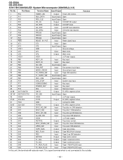
...T2_SOL Output Tape 2 solenoid control. 82 S49 T1_RUN_PLUS Input Tape 1 RUN PULSE input. 83 S50 T2_RUN_PLUS Input Tape 2 RUN PULSE input. CD-E500 CD-E55/E44 IC701 RH-iX0058SJZZ: System Microcomputer (IX0058SJ) (1/2) Pin No. Ground voltage. 15 CF1 CF1 Input Main clock. 16 CF2 CF2 Output...KEY1_IN Input Key input. 19 P81 KEY2_IN Input Key input. 20* P82 NO USE Input/Output Open 21 P83 FAN_PRT Input Fan protect circuit input. 22 P84 MODE_CKECK Input Ground level input. 23 P85 T2_TAPE2_SW Input Tape SW detection. 24* P86 T1_TAPE1_SW Input/Output...
...T2_SOL Output Tape 2 solenoid control. 82 S49 T1_RUN_PLUS Input Tape 1 RUN PULSE input. 83 S50 T2_RUN_PLUS Input Tape 2 RUN PULSE input. CD-E500 CD-E55/E44 IC701 RH-iX0058SJZZ: System Microcomputer (IX0058SJ) (1/2) Pin No. Ground voltage. 15 CF1 CF1 Input Main clock. 16 CF2 CF2 Output...KEY1_IN Input Key input. 19 P81 KEY2_IN Input Key input. 20* P82 NO USE Input/Output Open 21 P83 FAN_PRT Input Fan protect circuit input. 22 P84 MODE_CKECK Input Ground level input. 23 P85 T2_TAPE2_SW Input Tape SW detection. 24* P86 T1_TAPE1_SW Input/Output...
Service Manual
Page 51
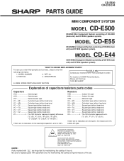
...) VR • • CZ Square type (without lead wire) VC J .. MODEL CD-E55 CD-E55 Mini Component System consisting of CD-E44 (main unit) and CP-E44 (speaker system). CAUTION:FOR CONTINUED PROTECTION AGAINST FIRE HAZARD, REPLACE ONLY WITH SAME TYPE F901,902 5A, 125V/ F903 1.6A,... DESCRIPTION For location of SHARP Parts Distributor, Please call Toll-Free; 1-800-BE-SHARP MARK: SPARE PARTS-DELIVERY SECTION Explanation of CD-E500 (main unit) and CP-E500 (speaker system). PARTS GUIDE CD-E500 CD-E55/E44 MINI COMPONENT SYSTEM MODEL CD-E500 CD-E500 Mini Component System ...
...) VR • • CZ Square type (without lead wire) VC J .. MODEL CD-E55 CD-E55 Mini Component System consisting of CD-E44 (main unit) and CP-E44 (speaker system). CAUTION:FOR CONTINUED PROTECTION AGAINST FIRE HAZARD, REPLACE ONLY WITH SAME TYPE F901,902 5A, 125V/ F903 1.6A,... DESCRIPTION For location of SHARP Parts Distributor, Please call Toll-Free; 1-800-BE-SHARP MARK: SPARE PARTS-DELIVERY SECTION Explanation of CD-E500 (main unit) and CP-E500 (speaker system). PARTS GUIDE CD-E500 CD-E55/E44 MINI COMPONENT SYSTEM MODEL CD-E500 CD-E500 Mini Component System ...


