
Service Manual
Page 1
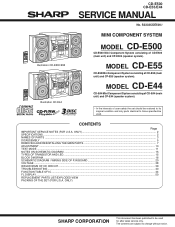
...SHARP CORPORATION This document has been published to be used for after sales service only. MODEL CD-E55 CD-E55 Mini Component System consisting of CD-E500 (main unit) and CP-E500 (speaker system). CONTENTS Page IMPORTANT SERVICE NOTES (FOR U.S.A. S3333CDE500// Illustration CD-E500/E55 Illustration CD-E44 MINI COMPONENT SYSTEM MODEL CD-E500 CD-E500 Mini Component System consisting of CD-E55... WAVEFORMS OF CD CIRCUIT ...39 TROUBLESHOOTING ...40 FUNCTION TABLE OF IC ...44 FL DISPLAY ...50 REPLACEMENT PARTS LIST/EXPLODED VIEW PACKING OF THE SET (FOR U.S.A. CD-E500 CD-E55/E44 SERVICE ...
...SHARP CORPORATION This document has been published to be used for after sales service only. MODEL CD-E55 CD-E55 Mini Component System consisting of CD-E500 (main unit) and CP-E500 (speaker system). CONTENTS Page IMPORTANT SERVICE NOTES (FOR U.S.A. S3333CDE500// Illustration CD-E500/E55 Illustration CD-E44 MINI COMPONENT SYSTEM MODEL CD-E500 CD-E500 Mini Component System consisting of CD-E55... WAVEFORMS OF CD CIRCUIT ...39 TROUBLESHOOTING ...40 FUNCTION TABLE OF IC ...44 FL DISPLAY ...50 REPLACEMENT PARTS LIST/EXPLODED VIEW PACKING OF THE SET (FOR U.S.A. CD-E500 CD-E55/E44 SERVICE ...
Service Manual
Page 2
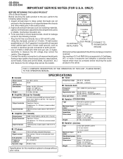
...is excessive and indicates a potential shock hazard which must be corrected before returning the audio product to all exposed metal cabinet parts and a known earth ground, such as insulating materials, cabinet, terminal board, adjustment and compartment covers or shields, mechanical... the resistor connection to the owner. FOR A COMPLETE DESCRIPTION OF THE OPERATION OF THIS UNIT, PLEASE REFER TO THE OPERATION MANUAL. CD-E500 CD-E55/E44 IMPORTANT SERVICE NOTES (FOR U.S.A. s General SPECIFICATIONS s Tuner Power source Power consumption Dimensions Weight AC 120 V, 60 Hz 96 ...
...is excessive and indicates a potential shock hazard which must be corrected before returning the audio product to all exposed metal cabinet parts and a known earth ground, such as insulating materials, cabinet, terminal board, adjustment and compartment covers or shields, mechanical... the resistor connection to the owner. FOR A COMPLETE DESCRIPTION OF THE OPERATION OF THIS UNIT, PLEASE REFER TO THE OPERATION MANUAL. CD-E500 CD-E55/E44 IMPORTANT SERVICE NOTES (FOR U.S.A. s General SPECIFICATIONS s Tuner Power source Power consumption Dimensions Weight AC 120 V, 60 Hz 96 ...
Service Manual
Page 3
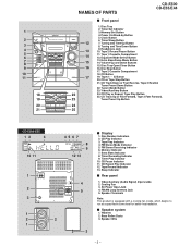
.... Tape (1 2) Button 20. Video/Auxiliary Button 22 24. Memory Indicator 7. Tape Record Indicator 13. s Speaker system 1. 1 2 3 4 5 6 7 8 9 10 11 18 19 20 21 NAMES OF PARTS CD-E500 CD-E55/E44 s Front panel 1. Memory/Set Button 4. Power On/Stand-by Button 5. Tuning and Time Down Button 9. Equalizer Mode Select Button 15 13. Disc Skip Button...
.... Tape (1 2) Button 20. Video/Auxiliary Button 22 24. Memory Indicator 7. Tape Record Indicator 13. s Speaker system 1. 1 2 3 4 5 6 7 8 9 10 11 18 19 20 21 NAMES OF PARTS CD-E500 CD-E55/E44 s Front panel 1. Memory/Set Button 4. Power On/Stand-by Button 5. Tuning and Time Down Button 9. Equalizer Mode Select Button 15 13. Disc Skip Button...
Service Manual
Page 7
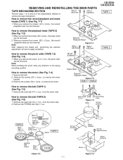
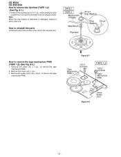
.... Remove the screws (D2) x 3 pcs., to remove the motor. (B1)x2 ø2x8mm Erase Head Record/ Playback Head Figure 7-2 TAPE 1 TAPE 2 CD-E500 CD-E55/E44 TAPE 1 TAPE 2 How to remove the motor (See Fig. 7-4) 1. Note: When installing the pinch roller, pay attention to remove the record/playback and...screws (A1) x 2 pcs., the record/ playback head can be removed. Remove the FF/REW belt (G2) x 1 pc. REMOVING AND REINSTALLING THE MAIN PARTS TAPE MECHANISM SECTION Perform steps 1 to 6 and 8 of the disassembly method to remove the tape mechanism. (A1)x1 ø2x7mm (A1)x1 ø2x3mm...
.... Remove the screws (D2) x 3 pcs., to remove the motor. (B1)x2 ø2x8mm Erase Head Record/ Playback Head Figure 7-2 TAPE 1 TAPE 2 CD-E500 CD-E55/E44 TAPE 1 TAPE 2 How to remove the motor (See Fig. 7-4) 1. Note: When installing the pinch roller, pay attention to remove the record/playback and...screws (A1) x 2 pcs., the record/ playback head can be removed. Remove the FF/REW belt (G2) x 1 pc. REMOVING AND REINSTALLING THE MAIN PARTS TAPE MECHANISM SECTION Perform steps 1 to 6 and 8 of the disassembly method to remove the tape mechanism. (A1)x1 ø2x7mm (A1)x1 ø2x3mm...
Service Manual
Page 8
... the tape mechanism PWB. 2. Remove the screw (J1) x 1 pc., to remove the tape mechanism PWB (TAPE 1,2) (See Fig. 8-2.) 1. CD-E500 CD-E55/E44 How to remove the tape mechanism PWB. Figure 8-1 Tape Mechanism PWB (J1)x1 ø2x3mm TAPE 1,2 (J2)x1 ø2x8mm Tape Mechanism ...- How to extract the flywheel from the capstan metal. Note: When the stop washer (H1) x 1 pc., with a small precision screwdriver to reinstall the parts Install each part in the reverse order of the removal with a new one. Remove the solder joints (J3) x 2 pcs., to remove the flywheel (TAPE 1,2) (See ...
... the tape mechanism PWB. 2. Remove the screw (J1) x 1 pc., to remove the tape mechanism PWB (TAPE 1,2) (See Fig. 8-2.) 1. CD-E500 CD-E55/E44 How to remove the tape mechanism PWB. Figure 8-1 Tape Mechanism PWB (J1)x1 ø2x3mm TAPE 1,2 (J2)x1 ø2x8mm Tape Mechanism ...- How to extract the flywheel from the capstan metal. Note: When the stop washer (H1) x 1 pc., with a small precision screwdriver to reinstall the parts Install each part in the reverse order of the removal with a new one. Remove the solder joints (J3) x 2 pcs., to remove the flywheel (TAPE 1,2) (See ...
Service Manual
Page 10
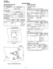
... modulated Tape TCC-119 speed Variable Resistor in Motor FM RF 98.00 MHz 98.00 MHz L302 *2 (10-30 dB) *1. clock wise) *1. CD-E500 CD-E55/E44 ADJUSTMENT MECHANISM SECTION TUNER SECTION • Driving Force Check Torque Meter Play: DM-300 Specified Value Tape 1: Over 80 g Tape 2: Over 80 ...TP301 12 IC301 FM MUTE Level T304 FM IF T306 AM BAND COVERAGE fL 1 L302 FM RF T302 AM TRACKING fL CNP301 Frequency Display Adjusting Parts Instrument Connection 98.00 MHz (26 dBµV) 98.00 MHz VR351*1 Input:CNP301 Output: Speaker Terminal *1. Coverage AM Tracking 990 kHz *1....
... modulated Tape TCC-119 speed Variable Resistor in Motor FM RF 98.00 MHz 98.00 MHz L302 *2 (10-30 dB) *1. clock wise) *1. CD-E500 CD-E55/E44 ADJUSTMENT MECHANISM SECTION TUNER SECTION • Driving Force Check Torque Meter Play: DM-300 Specified Value Tape 1: Over 80 g Tape 2: Over 80 ...TP301 12 IC301 FM MUTE Level T304 FM IF T306 AM BAND COVERAGE fL 1 L302 FM RF T302 AM TRACKING fL CNP301 Frequency Display Adjusting Parts Instrument Connection 98.00 MHz (26 dBµV) 98.00 MHz VR351*1 Input:CNP301 Output: Speaker Terminal *1. Coverage AM Tracking 990 kHz *1....
Service Manual
Page 15
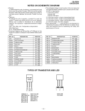
...M SSC1674 C KRC104 M 2SC2001 K KRC107 M - 15 - 123 KDV147B SVC348S Be sure to replace these parts with specified ones for maintaining the safety of the set . NOTES ON SCHEMATIC DIAGRAM CD-E500 CD-E55/E44 • Resistor: To differentiate the units of resistors, such symbol as K and M are used: ...the symbol K means 1000 ohm and the symbol M means 1000 kohm and the resistor without such a symbol is stopped. • Parts marked with " 1 "...
...M SSC1674 C KRC104 M 2SC2001 K KRC107 M - 15 - 123 KDV147B SVC348S Be sure to replace these parts with specified ones for maintaining the safety of the set . NOTES ON SCHEMATIC DIAGRAM CD-E500 CD-E55/E44 • Resistor: To differentiate the units of resistors, such symbol as K and M are used: ...the symbol K means 1000 ohm and the symbol M means 1000 kohm and the resistor without such a symbol is stopped. • Parts marked with " 1 "...
Service Manual
Page 40
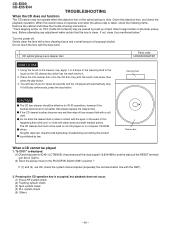
... lens of the RESET terminal (pin 66 on IC401). (2) Does the pickup move to the PICKUP-IN Switch (SW1) position ? CD optical pickup Lens cleaner disc Parts code UDSKA0004AFZZ HOW TO USE 1. If it contact with the bare hand. 1. Do not drink the cleaner fluid or allow it still... brush side down,then press the play continuously, press the stop . Gently clean the lens with the DSP). 2. CD-E500 CD-E55/E44 TROUBLESHOOTING When the CD does not function The CD section may be caused by law. Turn the power off any adjustment make certain that the lens is dirty. Unauthorized ...
... lens of the RESET terminal (pin 66 on IC401). (2) Does the pickup move to the PICKUP-IN Switch (SW1) position ? CD optical pickup Lens cleaner disc Parts code UDSKA0004AFZZ HOW TO USE 1. If it contact with the bare hand. 1. Do not drink the cleaner fluid or allow it still... brush side down,then press the play continuously, press the stop . Gently clean the lens with the DSP). 2. CD-E500 CD-E55/E44 TROUBLESHOOTING When the CD does not function The CD section may be caused by law. Turn the power off any adjustment make certain that the lens is dirty. Unauthorized ...
Service Manual
Page 51
... lead wire) VC J .. "HOW TO ORDER REPLACEMENT PARTS" To have your nearest SHARP Parts Distributor to replace parts with " " are ±5% carbon-film type. No. For U.S.A. only Contact your order filled promptly and correctly, please furnish the following information. 1. PART NO. 4. MODEL CD-E55 CD-E55 Mini Component System consisting of CD-E500 (main unit) and CP-E500 (speaker system...
... lead wire) VC J .. "HOW TO ORDER REPLACEMENT PARTS" To have your nearest SHARP Parts Distributor to replace parts with " " are ±5% carbon-film type. No. For U.S.A. only Contact your order filled promptly and correctly, please furnish the following information. 1. PART NO. 4. MODEL CD-E55 CD-E55 Mini Component System consisting of CD-E500 (main unit) and CP-E500 (speaker system...

Service Manual
Page 54
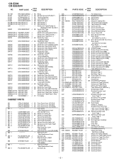
...R708 R709 R712~714 R715 R716~718 R719 R720~722 R725 R726,727 R728~732 R733 R734,735 R736~739 R742,743 R744 R744A PARTS CODE PRICE RANK DESCRIPTION VRS-CY1JB102J VRD-ST2CD103J VRD-ST2CD562J VRS-CY1JB222J VRD-ST2CD152J VRS-CY1JB103J VRD-ST2EE331J VRS-CY1JB562J VRD-ST2CD682J VRD-ST2CD562J...,1/6W J AA 2.7 kohms,1/6W J AA 10 kohm,1/6W J AA 1 kohm,1/6W J AA 10 kohm,1/6W J AA 1 kohm,1/6W J AA 47 kohms,1/6W - 3 - CD-E500 CD-E55/E44 NO. PART CODE PRICE RANK DESCRIPTION C901,902 C903~906 C907 C908 C909 C910 RC-GZA107AF1H J AC 100 µF,50V,Electrolytic VCFYFA1HA104J J AC 0.1 µF,50V,Thin...
...R708 R709 R712~714 R715 R716~718 R719 R720~722 R725 R726,727 R728~732 R733 R734,735 R736~739 R742,743 R744 R744A PARTS CODE PRICE RANK DESCRIPTION VRS-CY1JB102J VRD-ST2CD103J VRD-ST2CD562J VRS-CY1JB222J VRD-ST2CD152J VRS-CY1JB103J VRD-ST2EE331J VRS-CY1JB562J VRD-ST2CD682J VRD-ST2CD562J...,1/6W J AA 2.7 kohms,1/6W J AA 10 kohm,1/6W J AA 1 kohm,1/6W J AA 10 kohm,1/6W J AA 1 kohm,1/6W J AA 47 kohms,1/6W - 3 - CD-E500 CD-E55/E44 NO. PART CODE PRICE RANK DESCRIPTION C901,902 C903~906 C907 C908 C909 C910 RC-GZA107AF1H J AC 100 µF,50V,Electrolytic VCFYFA1HA104J J AC 0.1 µF,50V,Thin...

Service Manual
Page 55
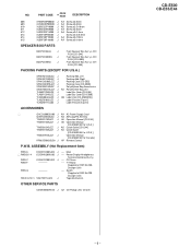
... 100 ohm,1/4W J AA 22 kohms,1/6W J AA 10 ohm,1/4W J AA 47 kohms,1/6W J AA 12 kohms,1/6W J AA 330 ohms,1/6W OTHER CIRCUITRY PARTS CN1 QCNWN0584SJZZ J CNP101 QCNCM050ESJZZ J CNP102 QCNCM999GAFZZ J CNP201 QCNCM998GAFZZ J CNP202 QCNCM059GSJZZ J CNP203 QCNCM046CSJZZ J CNP204 QCNCM999FAFZZ J CNP205 QCNCM999CAFZZ J CNP301 QCNCM042CSJZZ J CNP401 QCNCW014RSJZZ J CNP405 ...,1/6W J AA 150 ohms,1/6W J AA 3.3 kohms,1/6W J AA 2.2 kohms,1/6W J AA 56 kohms,1/6W J AA 1.5 kohms,1/6W J AA 10 kohm,1/6W CD-E500 CD-E55/E44 NO. Motor with Gear [Sled] (Supplied at REF No.238-1) - 4 - NO.
... 100 ohm,1/4W J AA 22 kohms,1/6W J AA 10 ohm,1/4W J AA 47 kohms,1/6W J AA 12 kohms,1/6W J AA 330 ohms,1/6W OTHER CIRCUITRY PARTS CN1 QCNWN0584SJZZ J CNP101 QCNCM050ESJZZ J CNP102 QCNCM999GAFZZ J CNP201 QCNCM998GAFZZ J CNP202 QCNCM059GSJZZ J CNP203 QCNCM046CSJZZ J CNP204 QCNCM999FAFZZ J CNP205 QCNCM999CAFZZ J CNP301 QCNCM042CSJZZ J CNP401 QCNCW014RSJZZ J CNP405 ...,1/6W J AA 150 ohms,1/6W J AA 3.3 kohms,1/6W J AA 2.2 kohms,1/6W J AA 56 kohms,1/6W J AA 1.5 kohms,1/6W J AA 10 kohm,1/6W CD-E500 CD-E55/E44 NO. Motor with Gear [Sled] (Supplied at REF No.238-1) - 4 - NO.
Service Manual
Page 56
...CD-E44] Rear Panel [CD-E500 For U.S.A.] AL Rear Panel [CD-E55 For U.S.A.] Rear Panel [CD-E55 For Canada] Rear Panel [CD-E500 For Canada] AE SHARP Badge AD Button,Power [CD-E44/55] AD Button,Power [CD-E500] AF Button,Function [CD-E44/55] AF Button,Function [CD-E500] AF Button,Stop/Play [CD... Ass'y AP Solenoid Ass'y -- Side Panel,Left (Not Replacement Item) Cushion,Leg Side Panel Ass'y,Right [CD-E44/55] Side Panel Ass'y,Right [CD-E500] -- PARTS CODE PRICE RANK DESCRIPTION RLY101 RRLYD0014AWZZ J RX701 VHLGP1UM271-1 J SO101 QTANA9024SJZZ J SO601 QSOCJ0003SJZZ J 1 SO901 QSOCA0214AWZZ ...
...CD-E44] Rear Panel [CD-E500 For U.S.A.] AL Rear Panel [CD-E55 For U.S.A.] Rear Panel [CD-E55 For Canada] Rear Panel [CD-E500 For Canada] AE SHARP Badge AD Button,Power [CD-E44/55] AD Button,Power [CD-E500] AF Button,Function [CD-E44/55] AF Button,Function [CD-E500] AF Button,Stop/Play [CD... Ass'y AP Solenoid Ass'y -- Side Panel,Left (Not Replacement Item) Cushion,Leg Side Panel Ass'y,Right [CD-E44/55] Side Panel Ass'y,Right [CD-E500] -- PARTS CODE PRICE RANK DESCRIPTION RLY101 RRLYD0014AWZZ J RX701 VHLGP1UM271-1 J SO101 QTANA9024SJZZ J SO601 QSOCJ0003SJZZ J 1 SO901 QSOCA0214AWZZ ...
Service Manual
Page 57
... Box Ass'y,L-CH/ R-CH [CD-E55] PACKING PARTS (EXCEPT FOR U.S.A.) SPAKA0134SJZZ SPAKA0135SJZZ SPAKC0286SJZZ SPAKC0287SJZZ SSAKA0014SJZZ SSAKH0021SJZZ TLABR1298SJZZ TLABR1299SJZZ TLABS0046SJZZ TLABZ0106SJZZ TLABZ0111SJZZ J Packing Add.,Left J Packing Add.,Right J Packing Case [CD-E55] J Packing Case [CD-E500] J Polyethylene Bag,Accessories J AD Polyethylene Bag,Unit J Label,Bar Code [CD-E55] J Label,Bar Code [CD-E500] J AB Label,CUL [CD-E500/E55] J Label,Feature [Tape...
... Box Ass'y,L-CH/ R-CH [CD-E55] PACKING PARTS (EXCEPT FOR U.S.A.) SPAKA0134SJZZ SPAKA0135SJZZ SPAKC0286SJZZ SPAKC0287SJZZ SSAKA0014SJZZ SSAKH0021SJZZ TLABR1298SJZZ TLABR1299SJZZ TLABS0046SJZZ TLABZ0106SJZZ TLABZ0111SJZZ J Packing Add.,Left J Packing Add.,Right J Packing Case [CD-E55] J Packing Case [CD-E500] J Polyethylene Bag,Accessories J AD Polyethylene Bag,Unit J Label,Bar Code [CD-E55] J Label,Bar Code [CD-E500] J AB Label,CUL [CD-E500/E55] J Label,Feature [Tape...

Service Manual
Page 58
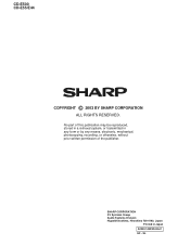
CD-E500 CD-E55/E44 202 615x2 608 A 202-1 234 608x2 602x2 PWB-A 615x2 233 202-2 B 607x2 606x2 205 612x2 IC101 606x2 238-1, 238-2, 238-3, 238-4, 238-5, 238-6 238 ...) 201-7 219-1 207 FLYWHEEL 219-3 219-2 FLYWHEEL ASS'Y MAIN BELT ASS'Y 226 TAPE2 TAPE1 H 208 203-2 203-1 203 608x2 Note: Only the unit and consumable parts are supplied as parts supply for the Tape mechanism. 1 2 3 4 5 6 Figure 7 CABINET EXPLODED VIEW - 7 -
CD-E500 CD-E55/E44 202 615x2 608 A 202-1 234 608x2 602x2 PWB-A 615x2 233 202-2 B 607x2 606x2 205 612x2 IC101 606x2 238-1, 238-2, 238-3, 238-4, 238-5, 238-6 238 ...) 201-7 219-1 207 FLYWHEEL 219-3 219-2 FLYWHEEL ASS'Y MAIN BELT ASS'Y 226 TAPE2 TAPE1 H 208 203-2 203-1 203 608x2 Note: Only the unit and consumable parts are supplied as parts supply for the Tape mechanism. 1 2 3 4 5 6 Figure 7 CABINET EXPLODED VIEW - 7 -
Service Manual
Page 60
No part of the publisher. SHARP CORPORATION AV Systems Group Audio Systems Division Higashihiroshima, Hiroshima 739-0192, Japan Printed in any form or by any means, electronic, mechanical, photocopying, recording, or otherwise, without prior written permission of this publication may be reproduced, stored in a retrieval system, or transmitted in Japan A0303-1459SS•HA•C SC • SL CD-E500 CD-E55/E44 COPYRIGHT © 2003 BY SHARP CORPORATION ALL RIGHTS RESERVED.
No part of the publisher. SHARP CORPORATION AV Systems Group Audio Systems Division Higashihiroshima, Hiroshima 739-0192, Japan Printed in any form or by any means, electronic, mechanical, photocopying, recording, or otherwise, without prior written permission of this publication may be reproduced, stored in a retrieval system, or transmitted in Japan A0303-1459SS•HA•C SC • SL CD-E500 CD-E55/E44 COPYRIGHT © 2003 BY SHARP CORPORATION ALL RIGHTS RESERVED.


