
Service Manual
Page 7
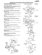
...Fig. 7-3) 1. When you remove the screw (C1) x 1 pc., the pinch roller can be removed. Remove the screws (D2) x 3 pcs., to remove the motor. (B1)x2 ø2x8mm Erase Head Record/ Playback Head Figure 7-2 TAPE 1 TAPE 2 CD-E500 CD-E55/E44 TAPE 1 TAPE 2 How to the spring mounting position.... Remove the main belt (F1) x 1 pc., from the motor side. 2. When you remove the screws (A1) x 2 pcs., the record/ playback head can be removed. Remove the belt. ...
...Fig. 7-3) 1. When you remove the screw (C1) x 1 pc., the pinch roller can be removed. Remove the screws (D2) x 3 pcs., to remove the motor. (B1)x2 ø2x8mm Erase Head Record/ Playback Head Figure 7-2 TAPE 1 TAPE 2 CD-E500 CD-E55/E44 TAPE 1 TAPE 2 How to the spring mounting position.... Remove the main belt (F1) x 1 pc., from the motor side. 2. When you remove the screws (A1) x 2 pcs., the record/ playback head can be removed. Remove the belt. ...
Service Manual
Page 8
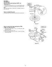
... Washerx2 Flywheel (H1)x1 Stop Washer Stop Driver Washer How to remove the flywheel (TAPE 1,2) (See Fig. 8-1.) 1. Remove the screw (J2) x 1 pc. 3. CD-E500 CD-E55/E44 How to remove the tape mechanism PWB (TAPE 1,2) (See Fig. 8-2.) 1. Remove the stop washer is deformed or damaged, replace it with a ...new one. Note: When the stop washer (H1) x 1 pc., with care. Figure 8-1 Tape Mechanism PWB (J1)x1 ø2x3mm TAPE 1,2 (J2)x1 ø2x8mm Tape Mechanism PWB Figure 8-2 (J3)x2 Solder Joint - ...
... Washerx2 Flywheel (H1)x1 Stop Washer Stop Driver Washer How to remove the flywheel (TAPE 1,2) (See Fig. 8-1.) 1. Remove the screw (J2) x 1 pc. 3. CD-E500 CD-E55/E44 How to remove the tape mechanism PWB (TAPE 1,2) (See Fig. 8-2.) 1. Remove the stop washer is deformed or damaged, replace it with a ...new one. Note: When the stop washer (H1) x 1 pc., with care. Figure 8-1 Tape Mechanism PWB (J1)x1 ø2x3mm TAPE 1,2 (J2)x1 ø2x8mm Tape Mechanism PWB Figure 8-2 (J3)x2 Solder Joint - ...
Service Manual
Page 9
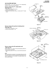
... Perform steps 1, 2, 3, 10,11, and 12 of the disassembly method to remove the CD mechanism. 1. Remove the belt (A2) x 1 pc. 3. How to remove the mechanism unit. CD-E500 CD-E55/E44 Loading Tray (A1)x2 ø2.4x3mm (A2)x1 T/T Motor PWB (A3)x2 ø3x10mm Loading Tray (Bottom View) T/T Rotate Motor Figure 9-1 Up/Down ...
... Perform steps 1, 2, 3, 10,11, and 12 of the disassembly method to remove the CD mechanism. 1. Remove the belt (A2) x 1 pc. 3. How to remove the mechanism unit. CD-E500 CD-E55/E44 Loading Tray (A1)x2 ø2.4x3mm (A2)x1 T/T Motor PWB (A3)x2 ø3x10mm Loading Tray (Bottom View) T/T Rotate Motor Figure 9-1 Up/Down ...