
Instructions for Use
Page 1
Instructions for use
Instructions for use
Instructions for Use
Page 2
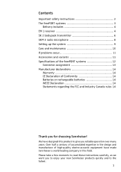
... 1 receiver 4 SK 2 bodypack transmitter 6 SKM 3 radio microphone 8 Setting up the system 9 Care and maintenance 10 If problems occur 11 Accessories and variants 11 Specifications of the freePORT systems 12 Connector assignment 13 Manufacturer declarations 14 Warranty 14 CE Declaration of Conformity 14 Batteries or rechargeable batteries 14 WEEE Declaration 14 Statements regarding the FCC and Industry Canada rules 14 Thank you reliable operation...
... 1 receiver 4 SK 2 bodypack transmitter 6 SKM 3 radio microphone 8 Setting up the system 9 Care and maintenance 10 If problems occur 11 Accessories and variants 11 Specifications of the freePORT systems 12 Connector assignment 13 Manufacturer declarations 14 Warranty 14 CE Declaration of Conformity 14 Batteries or rechargeable batteries 14 WEEE Declaration 14 Statements regarding the FCC and Industry Canada rules 14 Thank you reliable operation...
Instructions for Use
Page 3
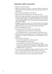
... the type of power source specified in the chapter "Specifications of the freePORT systems" on the device. y The mains unit must be operated only from the mains, - y Do not block any heat sources. y Refer all instructions. y Only use attachments/accessories specified by Sennheiser. 2 y Do not install the device and the mains unit near any ventilation openings. y Keep this instruction manual when passing the...
... the type of power source specified in the chapter "Specifications of the freePORT systems" on the device. y The mains unit must be operated only from the mains, - y Do not block any heat sources. y Refer all instructions. y Only use attachments/accessories specified by Sennheiser. 2 y Do not install the device and the mains unit near any ventilation openings. y Keep this instruction manual when passing the...
Instructions for Use
Page 4
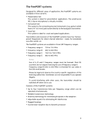
... Set: This system is for vocal and speech applications. y Vocal Set: This system is ideal for connecting musical instruments (e.g. The freePORT systems are available in three UHF frequency ranges: y Frequency range A: y Frequency range B: y Frequency range C: y Frequency range E: 719 to 721 MHz 691 to 693 MHz 742.5 to 744.5 MHz 863 to 693 MHz) is intended for direct channel selection - Sennheiser are available in use. To avoid interfering with other users, the transmitter...
... Set: This system is for vocal and speech applications. y Vocal Set: This system is ideal for connecting musical instruments (e.g. The freePORT systems are available in three UHF frequency ranges: y Frequency range A: y Frequency range B: y Frequency range C: y Frequency range E: 719 to 721 MHz 691 to 693 MHz 742.5 to 744.5 MHz 863 to 693 MHz) is intended for direct channel selection - Sennheiser are available in use. To avoid interfering with other users, the transmitter...
Instructions for Use
Page 5
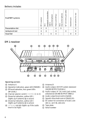
... 1 receiver SK 2 bodypack transmitter SKM 3 radio microphone Mains unit (NTxy) ME 2 clip-on microphone ¼" (6.3 mm) jack cable Stand mount Instructions for use Delivery includes FreePORT systems Presentation Set Instrument Set Vocal Set EM 1 receiver ³ XX XX X XX X X X X XX XX ᕢ » Operating controls ³ Antenna A · Operation indication, green LED (POWER) » RF level indication, four green LEDs (RF LEVEL) ¿ Channel selector switch CHANNEL (1 to 4) ´ Diversity indication, yellow LED A (lights up if antenna...
... 1 receiver SK 2 bodypack transmitter SKM 3 radio microphone Mains unit (NTxy) ME 2 clip-on microphone ¼" (6.3 mm) jack cable Stand mount Instructions for use Delivery includes FreePORT systems Presentation Set Instrument Set Vocal Set EM 1 receiver ³ XX XX X XX X X X X XX XX ᕢ » Operating controls ³ Antenna A · Operation indication, green LED (POWER) » RF level indication, four green LEDs (RF LEVEL) ¿ Channel selector switch CHANNEL (1 to 4) ´ Diversity indication, yellow LED A (lights up if antenna...
Instructions for Use
Page 6
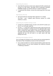
... mains cable into the DC socket Ƹ and connect it to the mains. which diversity section (i.e. The adjusted audio output level is active. Connecting the receiver ̈ Insert the DC connector on the new channel. ̈ Use a small screwdriver to set the channel selector switch ¿ to the desired channel. The green LED for operation indication (POWER) · lights up the antennas and align them upwards in an audio signal with...
... mains cable into the DC socket Ƹ and connect it to the mains. which diversity section (i.e. The adjusted audio output level is active. Connecting the receiver ̈ Insert the DC connector on the new channel. ̈ Use a small screwdriver to set the channel selector switch ¿ to the desired channel. The green LED for operation indication (POWER) · lights up the antennas and align them upwards in an audio signal with...

Instructions for Use
Page 7
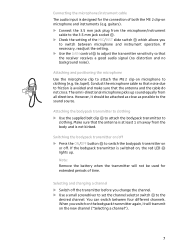
... transmitter Operating controls ³ ON/OFF button · Operation and battery status indication, red LED » Microphone/instrument input, 3.5 mm jack socket (lockable) ¿ Antenna (can be drastically reduced. ̈ Open the battery compartment by first sliding the battery compartment cover in the direction of the arrow. Note: When the red LED · goes off ) ´ Battery compartment cover ² MIC/INST slide switch ¶ Serial number º Channel selector switch CH...
... transmitter Operating controls ³ ON/OFF button · Operation and battery status indication, red LED » Microphone/instrument input, 3.5 mm jack socket (lockable) ¿ Antenna (can be drastically reduced. ̈ Open the battery compartment by first sliding the battery compartment cover in the direction of the arrow. Note: When the red LED · goes off ) ´ Battery compartment cover ² MIC/INST slide switch ¶ Serial number º Channel selector switch CH...
Instructions for Use
Page 8
... the setting of the MIC/INST slide switch ² which allows you switch on the bodypack transmitter again, it should be used for the connection of time. Connecting the microphone/instrument cable The audio input is switched on, the red LED · lights up sound equally from all directions. Conduct the microphone cable so that noise due to clothing. The omni-directional microphone picks up . Make sure that the antenna and the cable do...
... the setting of the MIC/INST slide switch ² which allows you switch on the bodypack transmitter again, it should be used for the connection of time. Connecting the microphone/instrument cable The audio input is switched on, the red LED · lights up sound equally from all directions. Conduct the microphone cable so that noise due to clothing. The omni-directional microphone picks up . Make sure that the antenna and the cable do...
Instructions for Use
Page 9
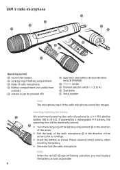
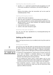
... ) ² Operation and battery status indication, red LED (POWER) ¶ ON/OFF switch º Channel selector switch CH (1 to 4) ¾ Type plate µ Serial number Note: The microphone head of the radio microphone cannot be drastically reduced. ̈ Turn the locking ring of the battery compartment · in the direction of the arrow. ̈ Pull the body of the radio microphone » in the direction of radio microphone ¿ Battery compartment (not...
... ) ² Operation and battery status indication, red LED (POWER) ¶ ON/OFF switch º Channel selector switch CH (1 to 4) ¾ Type plate µ Serial number Note: The microphone head of the radio microphone cannot be drastically reduced. ̈ Turn the locking ring of the battery compartment · in the direction of the arrow. ̈ Pull the body of the radio microphone » in the direction of radio microphone ¿ Battery compartment (not...
Instructions for Use
Page 10
... the radio microphone You can switch between transmitter and receiver. Selecting and changing a channel ̈ Switch off . y Do not operate the system close to 100 m. When using several trans- Sensitivity of 3 m between four different channels ("Selecting a channel"). ̈ Close and lock the radio microphone. ̈ Switch on the radio microphone again. mission links simultaneously, make sure that all four LEDs light up . Please observe the following: y Transmission range depends to the antenna...
... the radio microphone You can switch between transmitter and receiver. Selecting and changing a channel ̈ Switch off . y Do not operate the system close to 100 m. When using several trans- Sensitivity of 3 m between four different channels ("Selecting a channel"). ̈ Close and lock the radio microphone. ̈ Switch on the radio microphone again. mission links simultaneously, make sure that all four LEDs light up . Please observe the following: y Transmission range depends to the antenna...
Instructions for Use
Page 11
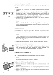
... units from time to other transmission links can be used together with intermodulation-free frequencies. Therefore, always adjust the squelch treshold to clean the sound inlet basket. ̈ Reinsert the dry foam insert, replace the sound inlet basket on the transmitter again and check if the receiver receives the transmitter signal. Note: These frequencies are different to those in this way, set the transmitter and the receiver to a different channel. ̈ Switch...
... units from time to other transmission links can be used together with intermodulation-free frequencies. Therefore, always adjust the squelch treshold to clean the sound inlet basket. ̈ Reinsert the dry foam insert, replace the sound inlet basket on the transmitter again and check if the receiver receives the transmitter signal. Note: These frequencies are different to those in this way, set the transmitter and the receiver to a different channel. ̈ Switch...
Instructions for Use
Page 12
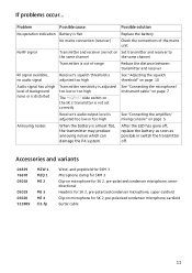
... condenser microphone, cardioid Guitar cable 11 Problem Possible cause Possible solution No operation indication Battery is flat Replace the battery No mains connection (receiver) Check the connections of the mains unit No RF signal Transmitter and receiver are not on Set transmitter and receiver to the same channel the same channel Transmitter is out of range Reduce the distance between transmitter and receiver RF signal available, no audio signal Receiver's squelch threshold is adjusted too high See "Adjusting the squelch threshold...
... condenser microphone, cardioid Guitar cable 11 Problem Possible cause Possible solution No operation indication Battery is flat Replace the battery No mains connection (receiver) Check the connections of the mains unit No RF signal Transmitter and receiver are not on Set transmitter and receiver to the same channel the same channel Transmitter is out of range Reduce the distance between transmitter and receiver RF signal available, no audio signal Receiver's squelch threshold is adjusted too high See "Adjusting the squelch threshold...
Instructions for Use
Page 13
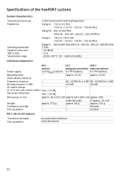
....90 MHz) Range C : 742.5 to 744.5 MHz (742.65 - 743.35 - 743.85 - 744.45 MHz) Range E: 863 to 865 MHz (863.10 - 863.70 - 864.10 - 864.90 MHz) 2 MHz > 95 dB(A) < 1 % -10 bis +45 °C / 95 relative humidity Individual components EM 1 SK 2 SKM 3 receiver bodypack transmitter radio microphone Power supply 12V DCNOM/100 mA 9 V PP3 battery 9 V PP3 battery Operating time -
....90 MHz) Range C : 742.5 to 744.5 MHz (742.65 - 743.35 - 743.85 - 744.45 MHz) Range E: 863 to 865 MHz (863.10 - 863.70 - 864.10 - 864.90 MHz) 2 MHz > 95 dB(A) < 1 % -10 bis +45 °C / 95 relative humidity Individual components EM 1 SK 2 SKM 3 receiver bodypack transmitter radio microphone Power supply 12V DCNOM/100 mA 9 V PP3 battery 9 V PP3 battery Operating time -
Instructions for Use
Page 14
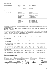
... be used licence-free in the USA and Canada. Frequency range 691 - 693 MHz: with US mains unit 719 - 721 MHz: with US mains unit 742.5 - 744.5 MHz: with EU mains unit with US mains unit 863 - 865 MHz: with EU mains unit with an appropriate radio transmission licence. Frequency range B is intended for power supply + 21 3 NC/GN D SK 2: 3.5 mm jack plug NC/GND Instr./MIC...
... be used licence-free in the USA and Canada. Frequency range 691 - 693 MHz: with US mains unit 719 - 721 MHz: with US mains unit 742.5 - 744.5 MHz: with EU mains unit with US mains unit 863 - 865 MHz: with EU mains unit with an appropriate radio transmission licence. Frequency range B is intended for power supply + 21 3 NC/GN D SK 2: 3.5 mm jack plug NC/GND Instr./MIC...

Instructions for Use
Page 15
... the receiving antenna. Operation is available on a circuit different from normal waste at the end of exhausted batteries. This equipment generates, uses and can be disposed of separately from that may void the FCC authorization to radio or television reception, which can radiate radio frequency energy and, if not installed and used in which we all live. WEEE Declaration Your Sennheiser...
... the receiving antenna. Operation is available on a circuit different from normal waste at the end of exhausted batteries. This equipment generates, uses and can be disposed of separately from that may void the FCC authorization to radio or television reception, which can radiate radio frequency energy and, if not installed and used in which we all live. WEEE Declaration Your Sennheiser...

Instructions for Use
Page 16
KG Am Labor 1 30900 Wedemark, Germany www.sennheiser.com Printed in Taiwan Publ. 08/08 514013/ A05 Sennheiser electronic GmbH & Co.
KG Am Labor 1 30900 Wedemark, Germany www.sennheiser.com Printed in Taiwan Publ. 08/08 514013/ A05 Sennheiser electronic GmbH & Co.


