
Assembly Manual
Page 2
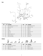
... Qty Description 1 1 Frame Assembly (includes Fan Assembly) 2 1 Locking Knob (Seat) 3 1 Seat Post 4 1 Seat 5 1 Console 6 2 Hand Grip 7 1 Arm, Left 8 1 Console Support Tube, Left 9 1 Spring, Locking Knob 10 1 Locking Knob (Wheel) Hardware Item Qty Description 11 1 Console Support Tube, Right 12 2 Console Cable Strap 13 1 Pedal, Left 14 2 Clevis Pin 15 2 Cotter Pin 16 4 Skid Resistance...
... Qty Description 1 1 Frame Assembly (includes Fan Assembly) 2 1 Locking Knob (Seat) 3 1 Seat Post 4 1 Seat 5 1 Console 6 2 Hand Grip 7 1 Arm, Left 8 1 Console Support Tube, Left 9 1 Spring, Locking Knob 10 1 Locking Knob (Wheel) Hardware Item Qty Description 11 1 Console Support Tube, Right 12 2 Console Cable Strap 13 1 Pedal, Left 14 2 Clevis Pin 15 2 Cotter Pin 16 4 Skid Resistance...

Assembly Manual
Page 6
Connect and Attach the Console Note: Do not crimp Console Cable. Connect the Console Cable to Console Support Tube. Use Console Cable Straps (#12) to secure Cable to the fan sensor on the right side of the Fan Assembly. * Hardware is pre-installed and not on the Hardware Card. 6 Attach Right and Left Console Support Tubes 8. 7.
Connect and Attach the Console Note: Do not crimp Console Cable. Connect the Console Cable to Console Support Tube. Use Console Cable Straps (#12) to secure Cable to the fan sensor on the right side of the Fan Assembly. * Hardware is pre-installed and not on the Hardware Card. 6 Attach Right and Left Console Support Tubes 8. 7.


