

Assembly Manual
Page 1
...(clockwise) to tighten, and the left (counterclockwise) to help insert the bolt through the holes. 5. Important Safety Instructions Schwinn ® AD4 Airdyne Assembly Manual 003-3240.021510.A This icon means a potentially hazardous situation which, if not avoided, could compromise the safety ....9" (163.6 cm x 246.1 cm). Read and understand the "Important Safety Instructions" before first use only genuine Schwinn® replacement parts and hardware supplied by US and Foreign Patents and Patents Pending. See Product for correct performance in accordance with the Owner's Manual...
...(clockwise) to tighten, and the left (counterclockwise) to help insert the bolt through the holes. 5. Important Safety Instructions Schwinn ® AD4 Airdyne Assembly Manual 003-3240.021510.A This icon means a potentially hazardous situation which, if not avoided, could compromise the safety ....9" (163.6 cm x 246.1 cm). Read and understand the "Important Safety Instructions" before first use only genuine Schwinn® replacement parts and hardware supplied by US and Foreign Patents and Patents Pending. See Product for correct performance in accordance with the Owner's Manual...
Assembly Manual
Page 2
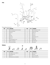
... (includes Fan Assembly) 2 1 Locking Knob (Seat) 3 1 Seat Post 4 1 Seat 5 1 Console 6 2 Hand Grip 7 1 Arm, Left 8 1 Console Support Tube, Left 9 1 Spring, Locking Knob 10 1 Locking Knob (Wheel) Hardware Item Qty Description 11 1 Console Support Tube, Right 12 2 Console Cable Strap 13 1 Pedal, Left 14 2 Clevis Pin 15 2 Cotter Pin 16 4 Skid Resistance Pad...
... (includes Fan Assembly) 2 1 Locking Knob (Seat) 3 1 Seat Post 4 1 Seat 5 1 Console 6 2 Hand Grip 7 1 Arm, Left 8 1 Console Support Tube, Left 9 1 Spring, Locking Knob 10 1 Locking Knob (Wheel) Hardware Item Qty Description 11 1 Console Support Tube, Right 12 2 Console Cable Strap 13 1 Pedal, Left 14 2 Clevis Pin 15 2 Cotter Pin 16 4 Skid Resistance Pad...

Assembly Manual
Page 6
Use Console Cable Straps (#12) to secure Cable to the fan sensor on the right side of the Fan Assembly. * Hardware is pre-installed and not on the Hardware Card. 6 Attach Right and Left Console Support Tubes 8. Connect and Attach the Console Note: Do not crimp Console Cable. Connect the Console Cable to Console Support Tube. 7.
Use Console Cable Straps (#12) to secure Cable to the fan sensor on the right side of the Fan Assembly. * Hardware is pre-installed and not on the Hardware Card. 6 Attach Right and Left Console Support Tubes 8. Connect and Attach the Console Note: Do not crimp Console Cable. Connect the Console Cable to Console Support Tube. 7.