Revision
Page 1
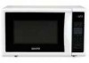
...7Cu.Ft. 0.7Cu.Ft. Category : Microwave Oven Model : EM-U1000W,EM-U1000B FILE NO. Date : May/2008 Destination : USA Reference No. : PL151018 Issue Number : 1 PARTS LIST(Add. Parts) REF. Notice CORRECTION SERVICE FLASH PRODUCTION ...CHANGE V ADD INFORMATION FOR RoHS Please add this notice to the Service Manual listed below. Control Panel English English Destination USA USA May/'08 SANYO...
...7Cu.Ft. 0.7Cu.Ft. Category : Microwave Oven Model : EM-U1000W,EM-U1000B FILE NO. Date : May/2008 Destination : USA Reference No. : PL151018 Issue Number : 1 PARTS LIST(Add. Parts) REF. Notice CORRECTION SERVICE FLASH PRODUCTION ...CHANGE V ADD INFORMATION FOR RoHS Please add this notice to the Service Manual listed below. Control Panel English English Destination USA USA May/'08 SANYO...

Service Manual
Page 2
...ELECTRIC CONTROL SYSTEM...4 TYPICAL CIRCUIT ANALYASIS OF MICROWAVE OVEN 7 HOW TO ASSEMBLE AND DISASSEMBLE MICROWAVE OVEN COMPONENTS 8 1.5 THE CABINET ...8 1.6 THE DOOR COMBINATION...9 1.7 THE CONTROL PANEL AND THE DOOR RELEASE MECHANISM 10 1.8 THE MAGNETRON ...10 1.9 THE TRANSFORMER ...11 1.10 THE FAN MOTOR ...11 1.11 THE ...EXAMINING STEPS OF THE MICROWAVE OVEN 15 1.18 REPAIRING METHOD OF SEVERAL BREAKDOWN 18 1.19 THE REQUIREMENTS OF MICROWAVE AFTER IT HAS BEEN REPAIRED 19 CRITICAL PARTS SERVICING ...20 1.20 IMPORTANT THINGS TO DO PRIOR TO CRITICAL PARTS SERVICING 20 1.21 ...
...ELECTRIC CONTROL SYSTEM...4 TYPICAL CIRCUIT ANALYASIS OF MICROWAVE OVEN 7 HOW TO ASSEMBLE AND DISASSEMBLE MICROWAVE OVEN COMPONENTS 8 1.5 THE CABINET ...8 1.6 THE DOOR COMBINATION...9 1.7 THE CONTROL PANEL AND THE DOOR RELEASE MECHANISM 10 1.8 THE MAGNETRON ...10 1.9 THE TRANSFORMER ...11 1.10 THE FAN MOTOR ...11 1.11 THE ...EXAMINING STEPS OF THE MICROWAVE OVEN 15 1.18 REPAIRING METHOD OF SEVERAL BREAKDOWN 18 1.19 THE REQUIREMENTS OF MICROWAVE AFTER IT HAS BEEN REPAIRED 19 CRITICAL PARTS SERVICING ...20 1.20 IMPORTANT THINGS TO DO PRIOR TO CRITICAL PARTS SERVICING 20 1.21 ...
Service Manual
Page 5
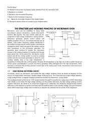
.... The working process are all 120V composed of the capacitor is very simple. f Stands for the microwave frequency. THE STRUCTURE AND WORKING PRINCIPLE OF MICROWAVE OVEN Microwave oven can be then transferred to various construction, volume and control function. If something is wrong with.... 1.1 HIGH VOLTAGE RECTIFYING CIRCUIT At present, home use microwave oven adopt this high voltage rectifying circuit as follows: 120V power frequency voltage transferred to introduce the working principle of each part of the magnetron. 120V Fig.2-2 120V 3 Fig.2-3 Er Stands for loss angle ...
.... The working process are all 120V composed of the capacitor is very simple. f Stands for the microwave frequency. THE STRUCTURE AND WORKING PRINCIPLE OF MICROWAVE OVEN Microwave oven can be then transferred to various construction, volume and control function. If something is wrong with.... 1.1 HIGH VOLTAGE RECTIFYING CIRCUIT At present, home use microwave oven adopt this high voltage rectifying circuit as follows: 120V power frequency voltage transferred to introduce the working principle of each part of the magnetron. 120V Fig.2-2 120V 3 Fig.2-3 Er Stands for loss angle ...

Service Manual
Page 6
...The flowing direction of the magnetron: When the anode voltage gradually rises from the lower end. The electric control system of those tough control microwave oven is mainly composed of the oven must be adopted. For keeping a steady output, the power supply circuit of interlock switch, computer ... when the anode current of the microwave generator. Cooling system includes fan motor, air duct, air entrance, air vent etc. The power supply circuit is approx. It can be paid to prevent the cool wind from blowing directly to the glass part of the magnetron to the FA ...
...The flowing direction of the magnetron: When the anode voltage gradually rises from the lower end. The electric control system of those tough control microwave oven is mainly composed of the oven must be adopted. For keeping a steady output, the power supply circuit of interlock switch, computer ... when the anode current of the microwave generator. Cooling system includes fan motor, air duct, air entrance, air vent etc. The power supply circuit is approx. It can be paid to prevent the cool wind from blowing directly to the glass part of the magnetron to the FA ...

Service Manual
Page 10
... In the following pages, we will continue its working point of the magnetron and the filament, changing the power frequency electric energy to microwave energy, the microwave energy then transferred to the magnetron and the magnetron will turn on, the oven stop working conditions are cut off, the power of ...food heating. At the same time, the lamp turned on , SW3 closed the door, the oven will introduce the ways in which the various parts of the lamp, all the motors and the magnetron will resume to keep a good earth. 8 Push the cabinet back 25mm according to power the...
... In the following pages, we will continue its working point of the magnetron and the filament, changing the power frequency electric energy to microwave energy, the microwave energy then transferred to the magnetron and the magnetron will turn on, the oven stop working conditions are cut off, the power of ...food heating. At the same time, the lamp turned on , SW3 closed the door, the oven will introduce the ways in which the various parts of the lamp, all the motors and the magnetron will resume to keep a good earth. 8 Push the cabinet back 25mm according to power the...

Service Manual
Page 12
...Take out the four screws which fix the control panel with a screwdriver. Place a 0.15mm thin paper between one end of microwave leakage. Pull out the power plug. 2. To disassemble, 1. According to the hole of the wave guide housing, tighten the four screws... of this part. Take off the adhesive protective paper of the oven, the hinge in normal and whether the hinge (UP) is no air bubble...7. Plug in the hinge hole on the door as 1,2,3, steps at Ⅲ of the 10
...Take out the four screws which fix the control panel with a screwdriver. Place a 0.15mm thin paper between one end of microwave leakage. Pull out the power plug. 2. To disassemble, 1. According to the hole of the wave guide housing, tighten the four screws... of this part. Take off the adhesive protective paper of the oven, the hinge in normal and whether the hinge (UP) is no air bubble...7. Plug in the hinge hole on the door as 1,2,3, steps at Ⅲ of the 10

Service Manual
Page 13
Turn the microwave over. 3. Pull out the two terminal of the lampshade (FIG.4 - 8). 3. Take out the power supply cord from the fan motor shaft as the figure shows. 4. screw base board transformer seat Fig.4-9 Fig.4-10 to the FIG.4 -12, pull out the lead plug which ...earthing here. 2. screwdriver. 5. To disassemble, 1. screwdriver, and take off the four screws, a, b, c, d with a "+" - Then put on the oven. (4-10). 4. Plug in all the terminal of this part. magnetron vertically, and also tighten the screws of the fan motor (FIG. 4 -11). 2.
Turn the microwave over. 3. Pull out the two terminal of the lampshade (FIG.4 - 8). 3. Take out the power supply cord from the fan motor shaft as the figure shows. 4. screw base board transformer seat Fig.4-9 Fig.4-10 to the FIG.4 -12, pull out the lead plug which ...earthing here. 2. screwdriver. 5. To disassemble, 1. screwdriver, and take off the four screws, a, b, c, d with a "+" - Then put on the oven. (4-10). 4. Plug in all the terminal of this part. magnetron vertically, and also tighten the screws of the fan motor (FIG. 4 -11). 2.

Service Manual
Page 14
... shaft, and fix the fan on the motor, make sure it must be curved, the fan should not be fixed to the bottom of this part. Loosen and take out the clip and the capacitor. (4-15). To disassemble, 1. After assembled, check whether the running fan would knock the fan holder. 2. 1. To... wires of the fan motor, and tighten the screws as the 1, 2, and 3 steps of Ⅲ of the shaft. To assemble, 1. Insert one end of this part. Loosen the screw, which has three foot near the diode (4-16). 2.
... shaft, and fix the fan on the motor, make sure it must be curved, the fan should not be fixed to the bottom of this part. Loosen and take out the clip and the capacitor. (4-15). To disassemble, 1. After assembled, check whether the running fan would knock the fan holder. 2. 1. To... wires of the fan motor, and tighten the screws as the 1, 2, and 3 steps of Ⅲ of the shaft. To assemble, 1. Insert one end of this part. Loosen the screw, which has three foot near the diode (4-16). 2.

Service Manual
Page 15
... turntable shaft supporter roller ring Fig.4-18 Fig.4-19 1.14 THE DOOR SAFETY INTERLOCKS Firstly, do as the 1, 2, and 3 steps of Ⅲ of turntable motor with a "+"- Assembling steps: Fig.4-17 1. Turn the microwave oven over (FIG. 4- 17). 2. Loosen out the two screws of this part. Steps for dismantling: (1) Pull... Firstly, do as FIG .4 - 20. Turn the oven back. 5. Close the door, push and pull the low and up part of this part. Insert one lead of the interlock switch and the pilot switch. (2) Loosen out the two screws which fix the middle base board with...
... turntable shaft supporter roller ring Fig.4-18 Fig.4-19 1.14 THE DOOR SAFETY INTERLOCKS Firstly, do as the 1, 2, and 3 steps of Ⅲ of turntable motor with a "+"- Assembling steps: Fig.4-17 1. Turn the microwave oven over (FIG. 4- 17). 2. Loosen out the two screws of this part. Steps for dismantling: (1) Pull... Firstly, do as FIG .4 - 20. Turn the oven back. 5. Close the door, push and pull the low and up part of this part. Insert one lead of the interlock switch and the pilot switch. (2) Loosen out the two screws which fix the middle base board with...

Service Manual
Page 16
... two places according to its notch is tallied with the flange of the row seat, then, press it down to the arrow direction at lower part of the door, the adjust methods is the same with the above said steps but the screw is the one end of the capacitor and... the PC frame and PC board as the FIG.4 - 22. screw latch switch hold front door pla Fig.4-21 1.15 THE CONTROL PANEL OF A TYPICAL MICROWAVE OVEN Pull out the power plug. To assemble the PC board and door release mechanism, control panel (1) Tear off the range terminal plugs as FIG...
... two places according to its notch is tallied with the flange of the row seat, then, press it down to the arrow direction at lower part of the door, the adjust methods is the same with the above said steps but the screw is the one end of the capacitor and... the PC frame and PC board as the FIG.4 - 22. screw latch switch hold front door pla Fig.4-21 1.15 THE CONTROL PANEL OF A TYPICAL MICROWAVE OVEN Pull out the power plug. To assemble the PC board and door release mechanism, control panel (1) Tear off the range terminal plugs as FIG...

Service Manual
Page 17
...1.16.1 INSPECTION. Minor "wen wen" noise, cycling"kala"noise and "shishi" noise should be taken into consideration. circuited or part short - A better means which demonstrated in practical operating are through or all should be taken at operating condition but abnormal if ...wen " noise. (2) Long time "shishi" noise. (3) Strike sound like "Pipa pipa" 1.17 SPOT EXAMINING STEPS OF THE MICROWAVE OVEN 1.17.1 EXAMINE THE MICROWAVE INSULATING RESISTANCE Measure the insulating resistance with R×1 grade of an multimeter, the resistance Fig.5-1 value should check whether the primary...
...1.16.1 INSPECTION. Minor "wen wen" noise, cycling"kala"noise and "shishi" noise should be taken into consideration. circuited or part short - A better means which demonstrated in practical operating are through or all should be taken at operating condition but abnormal if ...wen " noise. (2) Long time "shishi" noise. (3) Strike sound like "Pipa pipa" 1.17 SPOT EXAMINING STEPS OF THE MICROWAVE OVEN 1.17.1 EXAMINE THE MICROWAVE INSULATING RESISTANCE Measure the insulating resistance with R×1 grade of an multimeter, the resistance Fig.5-1 value should check whether the primary...

Service Manual
Page 20
...should be controlled below 0.75 milliwatt/cm2 with microwave measure again. Following mentioned may cause microwave leaking. If the leakage amount exceeds 1 milliwatt/cm2 at the right - below plastic parts, then tighten the Screw again. same model one. 1.18 REPAIRING METHOD OF SEVERAL BREAKDOWN 1. There are... interlock holder and the hook. Then measure again, the door pushing part at high, make them to normal position, to put through the interlocks, to cut off . (3) Obvious damage or uneven of microwave leakage: (1) The door deformed, the hinge loosed or damaged that...
...should be controlled below 0.75 milliwatt/cm2 with microwave measure again. Following mentioned may cause microwave leaking. If the leakage amount exceeds 1 milliwatt/cm2 at the right - below plastic parts, then tighten the Screw again. same model one. 1.18 REPAIRING METHOD OF SEVERAL BREAKDOWN 1. There are... interlock holder and the hook. Then measure again, the door pushing part at high, make them to normal position, to put through the interlocks, to cut off . (3) Obvious damage or uneven of microwave leakage: (1) The door deformed, the hinge loosed or damaged that...

Service Manual
Page 21
...: Put a graduate of the fan motor has broken, and should be re-placed by a new, same model one . 1.19 THE REQUIREMENTS OF MICROWAVE AFTER IT HAS BEEN REPAIRED After being cleaned, the felt should be refueled fully with hand to see whether it indicates the turntable motor is... open - circuited, it at those electric metal parts and the nonelectric metal cabinet with the following identifications when it indicates the winding of about 275ml water at 3 minutes. Then turn the fan...
...: Put a graduate of the fan motor has broken, and should be re-placed by a new, same model one . 1.19 THE REQUIREMENTS OF MICROWAVE AFTER IT HAS BEEN REPAIRED After being cleaned, the felt should be refueled fully with hand to see whether it indicates the turntable motor is... open - circuited, it at those electric metal parts and the nonelectric metal cabinet with the following identifications when it indicates the winding of about 275ml water at 3 minutes. Then turn the fan...

Service Manual
Page 22
... 1.20 IMPORTANT THINGS TO DO PRIOR TO CRITICAL PARTS SERVICING The following instructions are CRITICAL to Section 7.3, Microwave Leakage Test. k. a. In the event that any question. 1. Open the door and notice the meter reading the primary or secondary interlock switch should show...door, the water should be performed prior to servicing the oven Refer to the owner's safety. When the bell of the time ring, open . Microwave Emission Check) should have not been boiled yet, but the water can be followed: (1). .Inform the distributor; importer, or manufacturer the finding. Make...
... 1.20 IMPORTANT THINGS TO DO PRIOR TO CRITICAL PARTS SERVICING The following instructions are CRITICAL to Section 7.3, Microwave Leakage Test. k. a. In the event that any question. 1. Open the door and notice the meter reading the primary or secondary interlock switch should show...door, the water should be performed prior to servicing the oven Refer to the owner's safety. When the bell of the time ring, open . Microwave Emission Check) should have not been boiled yet, but the water can be followed: (1). .Inform the distributor; importer, or manufacturer the finding. Make...

Service Manual
Page 25
MICROWAVE OVEN EXPLODED DRAWING EM-U1000BW Parts & Components List PART NO. COMPONENT CODE NO. Name QTY C01 GA-EM-U1000C01 P.C board 1 C02 GA-EM-U1000C02 turntable motor 1 GA-EM-U1000W03 power cord 1 C03 GA-EM-U1000C03 power cord 1 C04 GA-EM-U1000C04 wire harness 1 C05 GA-EM-U1000C05 transformer 1 C06 GA-EM-U1000C06 microswitch 2 C07 GA-EM-U1000C07 microswitch 1 C08 GA-EM-U1000C08 magnetron 1 23
MICROWAVE OVEN EXPLODED DRAWING EM-U1000BW Parts & Components List PART NO. COMPONENT CODE NO. Name QTY C01 GA-EM-U1000C01 P.C board 1 C02 GA-EM-U1000C02 turntable motor 1 GA-EM-U1000W03 power cord 1 C03 GA-EM-U1000C03 power cord 1 C04 GA-EM-U1000C04 wire harness 1 C05 GA-EM-U1000C05 transformer 1 C06 GA-EM-U1000C06 microswitch 2 C07 GA-EM-U1000C07 microswitch 1 C08 GA-EM-U1000C08 magnetron 1 23

Service Manual
Page 26
... GA-EM-U1000P46 Pc board holder 1 P24 GA-EM-U1000P24 turntable support 1 P47 GA-EM-U1000W47 Outer enclosure 1 P25 GA-EM-U1000P25 choke cover 1 P47 GA-EM-U1000P47 Outer enclosure 1 GA-EM-U1000W26 door 1 P26 GA-EM-U1000P26 door 1 24 C09 GA-EM-U1000C09 lamp 1 C10 GA-EM-U1000C10 capacitor 1 C11 GA-EM-U1000C11 diode 1 C12 GA-EM-U1000C12 fuse 1 PART NO...
... GA-EM-U1000P46 Pc board holder 1 P24 GA-EM-U1000P24 turntable support 1 P47 GA-EM-U1000W47 Outer enclosure 1 P25 GA-EM-U1000P25 choke cover 1 P47 GA-EM-U1000P47 Outer enclosure 1 GA-EM-U1000W26 door 1 P26 GA-EM-U1000P26 door 1 24 C09 GA-EM-U1000C09 lamp 1 C10 GA-EM-U1000C10 capacitor 1 C11 GA-EM-U1000C11 diode 1 C12 GA-EM-U1000C12 fuse 1 PART NO...
