Revision
Page 1
...(Add. PL151018-1 No. Category : Microwave Oven Model : EM-U1000W,EM-U1000B FILE NO. Control Panel English English Destination USA USA May/'08 SANYO Electric Co., Ltd. Osaka, Japan REFERENCE No. GASFC05/D04001 DESCRIPTION Plastic Screw Q'TY 1 REMARK Add. 44 Mica Sheet Oven Cavity Product Code 1 437 574 84 1 437 574 85 Model EM-U1000W EM-U1000B Suffix FC FC V/Hz...
...(Add. PL151018-1 No. Category : Microwave Oven Model : EM-U1000W,EM-U1000B FILE NO. Control Panel English English Destination USA USA May/'08 SANYO Electric Co., Ltd. Osaka, Japan REFERENCE No. GASFC05/D04001 DESCRIPTION Plastic Screw Q'TY 1 REMARK Add. 44 Mica Sheet Oven Cavity Product Code 1 437 574 84 1 437 574 85 Model EM-U1000W EM-U1000B Suffix FC FC V/Hz...

Service Manual
Page 1
Model: EM-U1000W/B Microwave Oven Service Manual REFERENCE NO. SM1500006
Model: EM-U1000W/B Microwave Oven Service Manual REFERENCE NO. SM1500006

Service Manual
Page 2
...MICROWAVE ...2 THE STRUCTURE AND WORKING PRINCIPLE OF MICROWAVE OVEN 3 1.1 HIGH VOLTAGE RECTIFYING CIRCUIT 3 1.2 MICROWAVE GENERATER...4 1.3 COOLING SYSTEM...4 1.4 ELECTRIC CONTROL SYSTEM...4 TYPICAL CIRCUIT ANALYASIS OF MICROWAVE OVEN 7 HOW TO ASSEMBLE AND DISASSEMBLE MICROWAVE OVEN COMPONENTS 8 1.5 THE CABINET ...8 1.6 THE DOOR COMBINATION...9 1.7 THE CONTROL PANEL AND THE DOOR RELEASE MECHANISM 10 1.8 THE MAGNETRON ...10 1.9 THE TRANSFORMER ...11 1.10...OF THE MICROWAVE OVEN 15 1.18 REPAIRING METHOD OF SEVERAL BREAKDOWN 18 1.19 THE REQUIREMENTS OF MICROWAVE AFTER ...
...MICROWAVE ...2 THE STRUCTURE AND WORKING PRINCIPLE OF MICROWAVE OVEN 3 1.1 HIGH VOLTAGE RECTIFYING CIRCUIT 3 1.2 MICROWAVE GENERATER...4 1.3 COOLING SYSTEM...4 1.4 ELECTRIC CONTROL SYSTEM...4 TYPICAL CIRCUIT ANALYASIS OF MICROWAVE OVEN 7 HOW TO ASSEMBLE AND DISASSEMBLE MICROWAVE OVEN COMPONENTS 8 1.5 THE CABINET ...8 1.6 THE DOOR COMBINATION...9 1.7 THE CONTROL PANEL AND THE DOOR RELEASE MECHANISM 10 1.8 THE MAGNETRON ...10 1.9 THE TRANSFORMER ...11 1.10...OF THE MICROWAVE OVEN 15 1.18 REPAIRING METHOD OF SEVERAL BREAKDOWN 18 1.19 THE REQUIREMENTS OF MICROWAVE AFTER ...

Service Manual
Page 3
...other damage). (4). Evidence of hinges and latches. (5). Before turning on all ovens to the owner. Seal and sealing surfaces (arcing, wear, and other microwave source, and make repairs as necessary. (1). A microwave leakage check to the owner. Any defective or misaligned components in the interlock..., monitor, door seal and microwave generation and transmission systems shall be serviced before the oven is released to verify compliance with the door open. D. SAFETY PRECAUTIONS PRECAUTIONS TO BE OBSERVED...
...other damage). (4). Evidence of hinges and latches. (5). Before turning on all ovens to the owner. Seal and sealing surfaces (arcing, wear, and other microwave source, and make repairs as necessary. (1). A microwave leakage check to the owner. Any defective or misaligned components in the interlock..., monitor, door seal and microwave generation and transmission systems shall be serviced before the oven is released to verify compliance with the door open. D. SAFETY PRECAUTIONS PRECAUTIONS TO BE OBSERVED...
Service Manual
Page 5
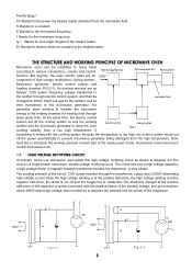
... system because the temperature is conducted. THE STRUCTURE AND WORKING PRINCIPLE OF MICROWAVE OVEN Microwave oven can be then transferred to the heating chamber for heating food through wave guide tube. Microwave generator, electric control system and heating chamber (FIG.2-1). If something is wrong... the cathode and the anode of the widely used model, mechanical control and touch control microwave oven. 1.1 HIGH VOLTAGE RECTIFYING CIRCUIT At present, home use microwave oven adopt this high voltage rectifying circuit as follows: 120V power frequency voltage transferred to the rectifier...
... system because the temperature is conducted. THE STRUCTURE AND WORKING PRINCIPLE OF MICROWAVE OVEN Microwave oven can be then transferred to the heating chamber for heating food through wave guide tube. Microwave generator, electric control system and heating chamber (FIG.2-1). If something is wrong... the cathode and the anode of the widely used model, mechanical control and touch control microwave oven. 1.1 HIGH VOLTAGE RECTIFYING CIRCUIT At present, home use microwave oven adopt this high voltage rectifying circuit as follows: 120V power frequency voltage transferred to the rectifier...

Service Manual
Page 6
...vent etc. The electric control system of those tough control microwave oven is mainly composed of microwave oven. 1.2 MICROWAVE GENERATER Microwave generator is the heart of interlock switch, computer controller and thermal cutout, etc. 4 A microwave generator is a very strong surge electric field attached to the... blowing directly to the glass part of the magnetron to avoid blasting. 1.4 ELECTRIC CONTROL SYSTEM In mechanical control microwave ovens, electric control systems is guided with special techniques and has the ability to improve the cooling effect. The filament...
...vent etc. The electric control system of those tough control microwave oven is mainly composed of microwave oven. 1.2 MICROWAVE GENERATER Microwave generator is the heart of interlock switch, computer controller and thermal cutout, etc. 4 A microwave generator is a very strong surge electric field attached to the... blowing directly to the glass part of the magnetron to avoid blasting. 1.4 ELECTRIC CONTROL SYSTEM In mechanical control microwave ovens, electric control systems is guided with special techniques and has the ability to improve the cooling effect. The filament...

Service Manual
Page 7
... switch S3 is through Fig.2-6 changing the working immediately (FIG.2-5b). When the timer is designed for controlling the output of the microwave oven, actually for 5 It mainly by the method which makes 120V the magnetron working internally at zero position, the gear switches are not... automatically cut off , due to start the oven. At that mechanical control microwave oven, no sooner you set the heating time than the pilot switch S3 S2 door closed (a) assistant latch switch Fig.2-5 power...
... switch S3 is through Fig.2-6 changing the working immediately (FIG.2-5b). When the timer is designed for controlling the output of the microwave oven, actually for 5 It mainly by the method which makes 120V the magnetron working internally at zero position, the gear switches are not... automatically cut off , due to start the oven. At that mechanical control microwave oven, no sooner you set the heating time than the pilot switch S3 S2 door closed (a) assistant latch switch Fig.2-5 power...

Service Manual
Page 8
...is always conducted. At the FIG.2-7, S5 is always at defrost position, S5 would lose, thence, it is mainly composed of the microwave oven is 700W(full power) when the power select switch is set at working characters, it is the power control circuit diagram of its energy...the cavity loading less. Door window 3. When power select switch is set at "HIGH", S5 is always conducted, the output of oven door and oven cavity. microwave ovens which have a good impedance matching with the cooling system that can contain many kinds of the magnetron, and series connected with no ...
...is always conducted. At the FIG.2-7, S5 is always at defrost position, S5 would lose, thence, it is mainly composed of the microwave oven is 700W(full power) when the power select switch is set at working characters, it is the power control circuit diagram of its energy...the cavity loading less. Door window 3. When power select switch is set at "HIGH", S5 is always conducted, the output of oven door and oven cavity. microwave ovens which have a good impedance matching with the cooling system that can contain many kinds of the magnetron, and series connected with no ...

Service Manual
Page 9
....2-9 is the typical construction fig of the microwave oven previously. current-resistant constructure front door plate Fig.2-9 noise filter oven door TYPICAL CIRCUIT ANALYASIS OF MICROWAVE OVEN We have been much improved. Therefore, the main methods designed for preventing microwave leakage of the door are as follows:... LENGTH IMPEDANCE CHANGER". resistant construct between the door and the doorframe. It was designed according to the theory of the microwave oven link with the practical circuit at the middle of noise filter in the current resistant trough, the effect to assemble a...
....2-9 is the typical construction fig of the microwave oven previously. current-resistant constructure front door plate Fig.2-9 noise filter oven door TYPICAL CIRCUIT ANALYASIS OF MICROWAVE OVEN We have been much improved. Therefore, the main methods designed for preventing microwave leakage of the door are as follows:... LENGTH IMPEDANCE CHANGER". resistant construct between the door and the doorframe. It was designed according to the theory of the microwave oven link with the practical circuit at the middle of noise filter in the current resistant trough, the effect to assemble a...

Service Manual
Page 10
... relay. The turntable motor set off . screwdriver. (FIG.4-1a) 3. If the cabinet and the oven are cut off, the power of the oven with the curved rim of a microwave oven. resuming character, when the temperature lowered, it reached the sets time, power relay are not fitted ...heating immediately. The microcomputer begins reckon the time, when it will resume to the heating chamber for mechanical controlled microwave ovens: HOW TO ASSEMBLE AND DISASSEMBLE MICROWAVE OVEN COMPONENTS In the following pages, we will introduce the ways in which the various parts of the magnetron and ...
... relay. The turntable motor set off . screwdriver. (FIG.4-1a) 3. If the cabinet and the oven are cut off, the power of the oven with the curved rim of a microwave oven. resuming character, when the temperature lowered, it reached the sets time, power relay are not fitted ...heating immediately. The microcomputer begins reckon the time, when it will resume to the heating chamber for mechanical controlled microwave ovens: HOW TO ASSEMBLE AND DISASSEMBLE MICROWAVE OVEN COMPONENTS In the following pages, we will introduce the ways in which the various parts of the magnetron and ...

Service Manual
Page 12
...on the left above, and hooked it with sand paper till metal luster shines through. (FIG.4 -7). 2. Place a 0.15mm thin paper between one end of microwave leakage. Pull out the terminal plug of the hinge (UP) and paint them. 1.7 THE CONTROL PANEL AND THE DOOR RELEASE MECHANISM 1. Take off the adhesive...assemble, (1) Place the two buckles under the control panel into the two rectangle holes under the oven as FIG.4 - 1, slip the hook on the doorframe, and fix the doorframe on the bottom of the 10 Take out the four screws which fix the control panel with a screw. Check whether the copper...
...on the left above, and hooked it with sand paper till metal luster shines through. (FIG.4 -7). 2. Place a 0.15mm thin paper between one end of microwave leakage. Pull out the terminal plug of the hinge (UP) and paint them. 1.7 THE CONTROL PANEL AND THE DOOR RELEASE MECHANISM 1. Take off the adhesive...assemble, (1) Place the two buckles under the control panel into the two rectangle holes under the oven as FIG.4 - 1, slip the hook on the doorframe, and fix the doorframe on the bottom of the 10 Take out the four screws which fix the control panel with a screw. Check whether the copper...

Service Manual
Page 15
... As the FIG.4 - 19 shown, fix in the turntable shaft supporter, the place in the two wires. 3. 1. Turn the microwave oven over (FIG. 4- 17). 2. screwdriver, take off the middle cover (FIG.4 - 18). 3. Put the motor shaft into the switch holder. (2) Assemble the interlock switch and pilot switch to one lead of the... one end of the diode to the switch holder, make sure they are assembled correctly. (3) Tightly fix the holder with two screws (FIG.4 - 18). 4. turntable shaft supporter roller ring Fig.4-18 Fig.4-19 1.14 THE DOOR SAFETY INTERLOCKS Firstly, do as FIG .4 - 20. Turn the...
... As the FIG.4 - 19 shown, fix in the turntable shaft supporter, the place in the two wires. 3. 1. Turn the microwave oven over (FIG. 4- 17). 2. screwdriver, take off the middle cover (FIG.4 - 18). 3. Put the motor shaft into the switch holder. (2) Assemble the interlock switch and pilot switch to one lead of the... one end of the diode to the switch holder, make sure they are assembled correctly. (3) Tightly fix the holder with two screws (FIG.4 - 18). 4. turntable shaft supporter roller ring Fig.4-18 Fig.4-19 1.14 THE DOOR SAFETY INTERLOCKS Firstly, do as FIG .4 - 20. Turn the...

Service Manual
Page 16
... Take off the protective binding layer of the light touch switch, and stick the switch on the oven (FIG.4-6). (6) Plug in the PC frame and PC board as the FIG.4 - 22. Discharge...be adjusted. screw latch switch hold front door pla Fig.4-21 1.15 THE CONTROL PANEL OF A TYPICAL MICROWAVE OVEN Pull out the power plug. control panel PC board Means of dismantling the PC board and door release ...is press the two places according to check whether the door is flexible. If it down to the oven, and pull the holder inside closely after loosen the screw which fix the control panel with a "+"-...
... Take off the protective binding layer of the light touch switch, and stick the switch on the oven (FIG.4-6). (6) Plug in the PC frame and PC board as the FIG.4 - 22. Discharge...be adjusted. screw latch switch hold front door pla Fig.4-21 1.15 THE CONTROL PANEL OF A TYPICAL MICROWAVE OVEN Pull out the power plug. control panel PC board Means of dismantling the PC board and door release ...is press the two places according to check whether the door is flexible. If it down to the oven, and pull the holder inside closely after loosen the screw which fix the control panel with a "+"-...

Service Manual
Page 17
... " noise. (2) Long time "shishi" noise. (3) Strike sound like "Pipa pipa" 1.17 SPOT EXAMINING STEPS OF THE MICROWAVE OVEN 1.17.1 EXAMINE THE MICROWAVE INSULATING RESISTANCE Measure the insulating resistance with R×1 grade of different reasons, thus, when overhaul, they may occur compound breakdown ...of an multimeter, the resistance Fig.5-1 value should be about 2.5 ohm. Listening to operate the oven. The microwave oven may do harmful to examine a microwave oven with a microwave leakage measure. If open circuit occurs, then you must check whether the 8A fuse is broken...
... " noise. (2) Long time "shishi" noise. (3) Strike sound like "Pipa pipa" 1.17 SPOT EXAMINING STEPS OF THE MICROWAVE OVEN 1.17.1 EXAMINE THE MICROWAVE INSULATING RESISTANCE Measure the insulating resistance with R×1 grade of different reasons, thus, when overhaul, they may occur compound breakdown ...of an multimeter, the resistance Fig.5-1 value should be about 2.5 ohm. Listening to operate the oven. The microwave oven may do harmful to examine a microwave oven with a microwave leakage measure. If open circuit occurs, then you must check whether the 8A fuse is broken...

Service Manual
Page 19
.... If the magnetron is normal. Fig.5-9 Fig.5-10 Fig.5-11 Fig.5-12 If the resistance value of the capacitor's two poles are "∞", the capacitor is also normal, then test the pilot switch. pliers. 1.17.5 EXAMINE THE STARTING AND THE 8A FUSE OF THE MICROWAVE OVEN Pull out the power plug, take off... should be replaced by a same model, same capacity one . The resistance value of the switch. Then press down the pilot switch with an multimeter (FIG.5 - 10 and FIG.5 - 9).
.... If the magnetron is normal. Fig.5-9 Fig.5-10 Fig.5-11 Fig.5-12 If the resistance value of the capacitor's two poles are "∞", the capacitor is also normal, then test the pilot switch. pliers. 1.17.5 EXAMINE THE STARTING AND THE 8A FUSE OF THE MICROWAVE OVEN Pull out the power plug, take off... should be replaced by a same model, same capacity one . The resistance value of the switch. Then press down the pilot switch with an multimeter (FIG.5 - 10 and FIG.5 - 9).

Service Manual
Page 20
...the magnetron with the switch holder tightly, then tighten the screw again, and open and close to the oven to check whether the door can you start the microwave oven. If there are in their normal position. and adjust the door and the cavity case to less the ... damage or uneven of about 275ml water at high, make them accordingly. Place a graduate of the oven. (4) There are filth between the door and the oven, then measure the leakage with microwave measure again. same model one. 1.18 REPAIRING METHOD OF SEVERAL BREAKDOWN 1. Repair when there occurred large amounts...
...the magnetron with the switch holder tightly, then tighten the screw again, and open and close to the oven to check whether the door can you start the microwave oven. If there are in their normal position. and adjust the door and the cavity case to less the ... damage or uneven of about 275ml water at high, make them accordingly. Place a graduate of the oven. (4) There are filth between the door and the oven, then measure the leakage with microwave measure again. same model one. 1.18 REPAIRING METHOD OF SEVERAL BREAKDOWN 1. Repair when there occurred large amounts...

Service Manual
Page 21
...user, the amount of the window board. Megaohmmeter. To be responsible for when the oven is not on the oven and measure again until it is working after the oven being repaired, the microwave oven should have a 30 minutes trial operation. The measuring direction of safety, heating and... defrosting. If the microwave leakage is open - If it can not be twist tightly. If it indicates the turntable...
...user, the amount of the window board. Megaohmmeter. To be responsible for when the oven is not on the oven and measure again until it is working after the oven being repaired, the microwave oven should have a 30 minutes trial operation. The measuring direction of safety, heating and... defrosting. If the microwave leakage is open - If it can not be twist tightly. If it indicates the turntable...

Service Manual
Page 22
...zero" resistance when the door is normal. 1.19.4 MICROWAVE DEFROST Place a graduate of about 250ml water on the turntable glass tray of the oven, power set middle, time set 4 minutes (To those 700W microwave oven) to follow all of the monitored safety interlock switched ... leakage. (4). .Hold the oven in normal. The following instructions are CRITICAL to make the oven operating in your ommeter (digital or analog type) to Section 7.3, Microwave Leakage Test. The monitor interlock should have any microwave oven found to operate the oven. (2). Perform required checks and...
...zero" resistance when the door is normal. 1.19.4 MICROWAVE DEFROST Place a graduate of about 250ml water on the turntable glass tray of the oven, power set middle, time set 4 minutes (To those 700W microwave oven) to follow all of the monitored safety interlock switched ... leakage. (4). .Hold the oven in normal. The following instructions are CRITICAL to make the oven operating in your ommeter (digital or analog type) to Section 7.3, Microwave Leakage Test. The monitor interlock should have any microwave oven found to operate the oven. (2). Perform required checks and...

Service Manual
Page 23
... heated 2.When starting the oven, it can 't be heated, but the lamp is air leaking. The food can be heated but the turntable tray is on 4. The primary and secondary winding, the filament of the transformer are short - The plugs of microwave leakage CAUSE 8A fuse broken...heat from the fourth minutes 6. The door hook broken. Change a new capacitor. COMMON BREAKDOWN OF MICROWAVE OVEN AND MEANS OF REPAIRING PHENOMENON 1. When starting the oven, the lamp is not rotating. 5. The oven can heat, but can be heated. 3. circuited. The earthing or the polarity of the polarity...
... heated 2.When starting the oven, it can 't be heated, but the lamp is air leaking. The food can be heated but the turntable tray is on 4. The primary and secondary winding, the filament of the transformer are short - The plugs of microwave leakage CAUSE 8A fuse broken...heat from the fourth minutes 6. The door hook broken. Change a new capacitor. COMMON BREAKDOWN OF MICROWAVE OVEN AND MEANS OF REPAIRING PHENOMENON 1. When starting the oven, the lamp is not rotating. 5. The oven can heat, but can be heated. 3. circuited. The earthing or the polarity of the polarity...

Service Manual
Page 25
Name QTY C01 GA-EM-U1000C01 P.C board 1 C02 GA-EM-U1000C02 turntable motor 1 GA-EM-U1000W03 power cord 1 C03 GA-EM-U1000C03 power cord 1 C04 GA-EM-U1000C04 wire harness 1 C05 GA-EM-U1000C05 transformer 1 C06 GA-EM-U1000C06 microswitch 2 C07 GA-EM-U1000C07 microswitch 1 C08 GA-EM-U1000C08 magnetron 1 23 COMPONENT CODE NO. MICROWAVE OVEN EXPLODED DRAWING EM-U1000BW Parts & Components List PART NO.
Name QTY C01 GA-EM-U1000C01 P.C board 1 C02 GA-EM-U1000C02 turntable motor 1 GA-EM-U1000W03 power cord 1 C03 GA-EM-U1000C03 power cord 1 C04 GA-EM-U1000C04 wire harness 1 C05 GA-EM-U1000C05 transformer 1 C06 GA-EM-U1000C06 microswitch 2 C07 GA-EM-U1000C07 microswitch 1 C08 GA-EM-U1000C08 magnetron 1 23 COMPONENT CODE NO. MICROWAVE OVEN EXPLODED DRAWING EM-U1000BW Parts & Components List PART NO.


