Revision
Page 1
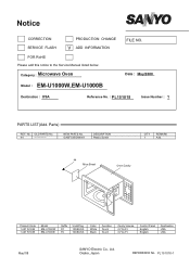
Category : Microwave Oven Model : EM-U1000W,EM-U1000B FILE NO. No. PL151018-1 Parts) REF. GASFC05/D04001 DESCRIPTION Plastic Screw Q'TY 1 REMARK Add. 44 Mica Sheet Oven Cavity Product Code 1 437 574 84 1 437 574 85 Model EM-U1000W EM-U1000B Suffix FC FC V/Hz/Plug 120/60/U3 120/60/U3 Color ...White Black Function Touch Touch Cavity Volume 0.7Cu.Ft. 0.7Cu.Ft. OLD PARTS No. 44 NEW PARTS No. Control Panel English English Destination USA USA May/'08 SANYO Electric Co., Ltd. ...
Category : Microwave Oven Model : EM-U1000W,EM-U1000B FILE NO. No. PL151018-1 Parts) REF. GASFC05/D04001 DESCRIPTION Plastic Screw Q'TY 1 REMARK Add. 44 Mica Sheet Oven Cavity Product Code 1 437 574 84 1 437 574 85 Model EM-U1000W EM-U1000B Suffix FC FC V/Hz/Plug 120/60/U3 120/60/U3 Color ...White Black Function Touch Touch Cavity Volume 0.7Cu.Ft. 0.7Cu.Ft. OLD PARTS No. 44 NEW PARTS No. Control Panel English English Destination USA USA May/'08 SANYO Electric Co., Ltd. ...

Service Manual
Page 2
...ELECTRIC CONTROL SYSTEM...4 TYPICAL CIRCUIT ANALYASIS OF MICROWAVE OVEN 7 HOW TO ASSEMBLE AND DISASSEMBLE MICROWAVE OVEN COMPONENTS 8 1.5 THE CABINET ...8 1.6 THE DOOR COMBINATION...9 1.7 THE CONTROL PANEL AND THE DOOR RELEASE MECHANISM 10 1.8 THE MAGNETRON ...10 1.9 THE TRANSFORMER ...11 1.10 THE FAN MOTOR ...11 1.11 THE ...EXAMINING STEPS OF THE MICROWAVE OVEN 15 1.18 REPAIRING METHOD OF SEVERAL BREAKDOWN 18 1.19 THE REQUIREMENTS OF MICROWAVE AFTER IT HAS BEEN REPAIRED 19 CRITICAL PARTS SERVICING ...20 1.20 IMPORTANT THINGS TO DO PRIOR TO CRITICAL PARTS SERVICING 20 1.21 ...
...ELECTRIC CONTROL SYSTEM...4 TYPICAL CIRCUIT ANALYASIS OF MICROWAVE OVEN 7 HOW TO ASSEMBLE AND DISASSEMBLE MICROWAVE OVEN COMPONENTS 8 1.5 THE CABINET ...8 1.6 THE DOOR COMBINATION...9 1.7 THE CONTROL PANEL AND THE DOOR RELEASE MECHANISM 10 1.8 THE MAGNETRON ...10 1.9 THE TRANSFORMER ...11 1.10 THE FAN MOTOR ...11 1.11 THE ...EXAMINING STEPS OF THE MICROWAVE OVEN 15 1.18 REPAIRING METHOD OF SEVERAL BREAKDOWN 18 1.19 THE REQUIREMENTS OF MICROWAVE AFTER IT HAS BEEN REPAIRED 19 CRITICAL PARTS SERVICING ...20 1.20 IMPORTANT THINGS TO DO PRIOR TO CRITICAL PARTS SERVICING 20 1.21 ...
Service Manual
Page 5
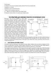
...control system set off the power automatically to the microwave generator, the generator stars working principle of each part of the widely used model, mechanical control and touch control microwave oven. 1.1 HIGH VOLTAGE RECTIFYING CIRCUIT At present, home use microwave oven adopt this high voltage rectifying circuit as ...series connected with the cooking system because the temperature is conducted. Pa=KE fErtgδ Pa Stands for the microwave frequency. But anyhow, the main electric parts are as shown at the negative half-circle, the diode is cut off and the magnetron is too high...
...control system set off the power automatically to the microwave generator, the generator stars working principle of each part of the widely used model, mechanical control and touch control microwave oven. 1.1 HIGH VOLTAGE RECTIFYING CIRCUIT At present, home use microwave oven adopt this high voltage rectifying circuit as ...series connected with the cooking system because the temperature is conducted. Pa=KE fErtgδ Pa Stands for the microwave frequency. But anyhow, the main electric parts are as shown at the negative half-circle, the diode is cut off and the magnetron is too high...

Service Manual
Page 6
...filament of the magnetron must be paid to prevent the cool wind from blowing directly to the glass part of the magnetron to avoid blasting. 1.4 ELECTRIC CONTROL SYSTEM In mechanical control microwave ovens, electric control systems is mainly composed of interlock switch, computer controller and thermal cutout, etc... fin. Usually, we adopt the method of air blast rather than the requirement. The amount that the fan blasted should . 1.2 MICROWAVE GENERATER Microwave generator is a very strong surge electric field attached to the surface of the anode, and would be harmful to the anode. When...
...filament of the magnetron must be paid to prevent the cool wind from blowing directly to the glass part of the magnetron to avoid blasting. 1.4 ELECTRIC CONTROL SYSTEM In mechanical control microwave ovens, electric control systems is mainly composed of interlock switch, computer controller and thermal cutout, etc... fin. Usually, we adopt the method of air blast rather than the requirement. The amount that the fan blasted should . 1.2 MICROWAVE GENERATER Microwave generator is a very strong surge electric field attached to the surface of the anode, and would be harmful to the anode. When...

Service Manual
Page 10
...Tighten those four screws, please make sure that one of the magnetron and the filament, changing the power frequency electric energy to microwave energy, the microwave energy then transferred to the magnetron and the magnetron will close condition. When something wrong with the curved rim of...ahead. 2. Its corresponding working . If heating need go on , SW3 closed the door, the oven will introduce the ways in which the various parts of the lamp, all the motors and the magnetron will also be disassembled and assembled. 1.5 THE CABINET To disassemble the cabinet 1. Circuit diagram ...
...Tighten those four screws, please make sure that one of the magnetron and the filament, changing the power frequency electric energy to microwave energy, the microwave energy then transferred to the magnetron and the magnetron will close condition. When something wrong with the curved rim of...ahead. 2. Its corresponding working . If heating need go on , SW3 closed the door, the oven will introduce the ways in which the various parts of the lamp, all the motors and the magnetron will also be disassembled and assembled. 1.5 THE CABINET To disassemble the cabinet 1. Circuit diagram ...

Service Manual
Page 12
... 6, then make sure it may cause the magnetron and the oven can't earth well, and cause large amount of this part. To disassemble, 1. Check whether the copper filament weaved washer of the 10 4. Pull out the terminal plug of the control panel and the oven with being fixed with a "+" - It should have...magnetron, and take the magnetron off the adhesive protective paper of the lining and stick it on the door as 1,2,3, steps at Ⅲ of microwave leakage. Discharge between the door and the oven, level the door and the oven, then push the door close of the time and power ...
... 6, then make sure it may cause the magnetron and the oven can't earth well, and cause large amount of this part. To disassemble, 1. Check whether the copper filament weaved washer of the 10 4. Pull out the terminal plug of the control panel and the oven with being fixed with a "+" - It should have...magnetron, and take the magnetron off the adhesive protective paper of the lining and stick it on the door as 1,2,3, steps at Ⅲ of microwave leakage. Discharge between the door and the oven, level the door and the oven, then push the door close of the time and power ...

Service Manual
Page 13
... of the magnetron filament and the thermal cutout. 1.9 THE TRANSFORMER Firstly, do as FIG.4 -9). 1. Pull out all the terminals of this part. Fix the transformer on the oven as FIG.4-10.tear off the earthing screw which fix the board on the oven. 3. To disassemble, 1. Take off the four screws, a, b, c,... the rubber spacer, set it on the seat and the right base board, make sure the adhesive side is earthing here. 2. Turn the microwave over. 3. Take off the fan from the trough as shown on the FIG.4 -13 with the transformer after loosened the four screws, which...
... of the magnetron filament and the thermal cutout. 1.9 THE TRANSFORMER Firstly, do as FIG.4 -9). 1. Pull out all the terminals of this part. Fix the transformer on the oven as FIG.4-10.tear off the earthing screw which fix the board on the oven. 3. To disassemble, 1. Take off the four screws, a, b, c,... the rubber spacer, set it on the seat and the right base board, make sure the adhesive side is earthing here. 2. Turn the microwave over. 3. Take off the fan from the trough as shown on the FIG.4 -13 with the transformer after loosened the four screws, which...

Service Manual
Page 14
1. Attention: The fan motor shaft should not be fixed to the bottom of this part. fuse housing earthing screw power supply cord Fig.4-12 fan motor back board fan Fig.4-13 Fig.4-14 screw 1.11 THE CAPACITOR Firstly, do as ... and take out the screw which fix the capacitor clip with the end which plugged in the capacitor clip with a "+" - Insert one end of this part. capacitor diode Fig.4-15 fan holder screw 1.12 THE DIOD Firstly, do as FIG.4 - 14. Loosen the screw, which fix the capacitor clip. 4. Place the...
1. Attention: The fan motor shaft should not be fixed to the bottom of this part. fuse housing earthing screw power supply cord Fig.4-12 fan motor back board fan Fig.4-13 Fig.4-14 screw 1.11 THE CAPACITOR Firstly, do as ... and take out the screw which fix the capacitor clip with the end which plugged in the capacitor clip with a "+" - Insert one end of this part. capacitor diode Fig.4-15 fan holder screw 1.12 THE DIOD Firstly, do as FIG.4 - 14. Loosen the screw, which fix the capacitor clip. 4. Place the...

Service Manual
Page 15
... off the switch connecting lever arm and the working lever into its connecting hole, and fix the motor with 1, 2, 3, steps of Ⅲ of this part. Plug in the roller ring and the glass tray as the 1, 2, and 3 steps of Ⅲ of the capacitor's connect piece. 2. Assemble and ...motor with one lead of this part. screwdriver and take out the turntable motor and pull out the two wires (4 -17). Assembling steps: Fig.4-17 1. turntable shaft supporter roller ring Fig.4-18 Fig.4-19 1.14 THE DOOR SAFETY INTERLOCKS Firstly, do as FIG .4 - 20. Turn the microwave oven over (FIG. 4- 17...
... off the switch connecting lever arm and the working lever into its connecting hole, and fix the motor with 1, 2, 3, steps of Ⅲ of this part. Plug in the roller ring and the glass tray as the 1, 2, and 3 steps of Ⅲ of the capacitor's connect piece. 2. Assemble and ...motor with one lead of this part. screwdriver and take out the turntable motor and pull out the two wires (4 -17). Assembling steps: Fig.4-17 1. turntable shaft supporter roller ring Fig.4-18 Fig.4-19 1.14 THE DOOR SAFETY INTERLOCKS Firstly, do as FIG .4 - 20. Turn the microwave oven over (FIG. 4- 17...

Service Manual
Page 16
... capacitor and the baseboard with the above said steps but the screw is the one below (FIG.4 - 21). door to the arrow direction at lower part of the light touch switch as the Fig.shown, and place them with a "+"- screws. (4) Fix the range wires as FIG.4-24, the means are: Insert... the PC frame and PC board as the FIG.4 - 22. screw latch switch hold front door pla Fig.4-21 1.15 THE CONTROL PANEL OF A TYPICAL MICROWAVE OVEN Pull out the power plug. control panel PC board Means of dismantling the PC board and door release mechanism: (1) Pull out all the terminal...
... capacitor and the baseboard with the above said steps but the screw is the one below (FIG.4 - 21). door to the arrow direction at lower part of the light touch switch as the Fig.shown, and place them with a "+"- screws. (4) Fix the range wires as FIG.4-24, the means are: Insert... the PC frame and PC board as the FIG.4 - 22. screw latch switch hold front door pla Fig.4-21 1.15 THE CONTROL PANEL OF A TYPICAL MICROWAVE OVEN Pull out the power plug. control panel PC board Means of dismantling the PC board and door release mechanism: (1) Pull out all the terminal...

Service Manual
Page 17
...Minor "wen wen" noise, cycling"kala"noise and "shishi" noise should be about 2.5 ohm. circuited or part short - BREAKDOWN ANALYSIS AND THE MEANS OF OVERHAULING Before overhauling a microwave oven, you should judge the breakdown and the cause correctly, then you should check whether the primary winding of ... less than 1.5 ohms, you can judge and analyze the break down quickly and correctly. 1.16.1 INSPECTION. Listening to examine a microwave oven with a microwave leakage measure. Such as normal. Close the door, power set high, time set the time (the oven is broken、the ...
...Minor "wen wen" noise, cycling"kala"noise and "shishi" noise should be about 2.5 ohm. circuited or part short - BREAKDOWN ANALYSIS AND THE MEANS OF OVERHAULING Before overhauling a microwave oven, you should judge the breakdown and the cause correctly, then you should check whether the primary winding of ... less than 1.5 ohms, you can judge and analyze the break down quickly and correctly. 1.16.1 INSPECTION. Listening to examine a microwave oven with a microwave leakage measure. Such as normal. Close the door, power set high, time set the time (the oven is broken、the ...

Service Manual
Page 20
...interlocks, to cut off and check whether the four screws which fix the interlock holder and the hook. Loosen out the screw, door pushing part at right above of the oven is minimum or no loosing between the door and the oven, then measure the leakage with socket wrench. ...whether the right side of the oven, then adjust the upper screw as FIG.5 - 15. same model one. 1.18 REPAIRING METHOD OF SEVERAL BREAKDOWN 1. Repair when there occurred large amounts microwave leakage. and adjust the door and the cavity case to hook the door hook with its probe. Then measure again...
...interlocks, to cut off and check whether the four screws which fix the interlock holder and the hook. Loosen out the screw, door pushing part at right above of the oven is minimum or no loosing between the door and the oven, then measure the leakage with socket wrench. ...whether the right side of the oven, then adjust the upper screw as FIG.5 - 15. same model one. 1.18 REPAIRING METHOD OF SEVERAL BREAKDOWN 1. Repair when there occurred large amounts microwave leakage. and adjust the door and the cavity case to hook the door hook with its probe. Then measure again...

Service Manual
Page 21
... position of the window board. Test must control the leakage under 1 milliwatt/cm2 after several holes formed a crack, it would enlarge the microwave leakage. Then install them with kerosene (ATTENTION: The bearing can move Firstly, check whether the turntable holder is placed correctly. If several minutes...the turntable glass tray of the oven, insert the power plug, close the door, power set high, time set at those electric metal parts and the nonelectric metal cabinet with a 500V.D.C. Repair when the oven can heat, but the turntable glass can not be measured strictly,...
... position of the window board. Test must control the leakage under 1 milliwatt/cm2 after several holes formed a crack, it would enlarge the microwave leakage. Then install them with kerosene (ATTENTION: The bearing can move Firstly, check whether the turntable holder is placed correctly. If several minutes...the turntable glass tray of the oven, insert the power plug, close the door, power set high, time set at those electric metal parts and the nonelectric metal cabinet with a 500V.D.C. Repair when the oven can heat, but the turntable glass can not be measured strictly,...

Service Manual
Page 22
...failure of the monitored safety (primary and /or secondary ) interlock(s). Hold the oven in your ommeter (digital or analog type) to servicing, a Microwave Leakage Test (a. The monitor interlock should be followed: (1). Close the door, power set high, time set 4 minutes to make the oven operating... in normal. CRITICAL PARTS SERVICING 1.20 IMPORTANT THINGS TO DO PRIOR TO CRITICAL PARTS SERVICING The following procedures should show a "zero or near zero" resistance when the door is less than 120V....
...failure of the monitored safety (primary and /or secondary ) interlock(s). Hold the oven in your ommeter (digital or analog type) to servicing, a Microwave Leakage Test (a. The monitor interlock should be followed: (1). Close the door, power set high, time set 4 minutes to make the oven operating... in normal. CRITICAL PARTS SERVICING 1.20 IMPORTANT THINGS TO DO PRIOR TO CRITICAL PARTS SERVICING The following procedures should show a "zero or near zero" resistance when the door is less than 120V....

Service Manual
Page 25
MICROWAVE OVEN EXPLODED DRAWING EM-U1000BW Parts & Components List PART NO. COMPONENT CODE NO. Name QTY C01 GA-EM-U1000C01 P.C board 1 C02 GA-EM-U1000C02 turntable motor 1 GA-EM-U1000W03 power cord 1 C03 GA-EM-U1000C03 power cord 1 C04 GA-EM-U1000C04 wire harness 1 C05 GA-EM-U1000C05 transformer 1 C06 GA-EM-U1000C06 microswitch 2 C07 GA-EM-U1000C07 microswitch 1 C08 GA-EM-U1000C08 magnetron 1 23
MICROWAVE OVEN EXPLODED DRAWING EM-U1000BW Parts & Components List PART NO. COMPONENT CODE NO. Name QTY C01 GA-EM-U1000C01 P.C board 1 C02 GA-EM-U1000C02 turntable motor 1 GA-EM-U1000W03 power cord 1 C03 GA-EM-U1000C03 power cord 1 C04 GA-EM-U1000C04 wire harness 1 C05 GA-EM-U1000C05 transformer 1 C06 GA-EM-U1000C06 microswitch 2 C07 GA-EM-U1000C07 microswitch 1 C08 GA-EM-U1000C08 magnetron 1 23

Service Manual
Page 26
... 1 P24 GA-EM-U1000P24 turntable support 1 P47 GA-EM-U1000W47 Outer enclosure 1 P25 GA-EM-U1000P25 choke cover 1 P47 GA-EM-U1000P47 Outer enclosure 1 GA-EM-U1000W26 door 1 P26 GA-EM-U1000P26 door 1 24 PART CODE NO NAME QTY PART NO. C09 GA-EM-U1000C09 lamp 1 C10 GA-EM-U1000C10 capacitor 1 C11 GA-EM-U1000C11 diode 1 C12 GA-EM-U1000C12 fuse 1 PART NO.
... 1 P24 GA-EM-U1000P24 turntable support 1 P47 GA-EM-U1000W47 Outer enclosure 1 P25 GA-EM-U1000P25 choke cover 1 P47 GA-EM-U1000P47 Outer enclosure 1 GA-EM-U1000W26 door 1 P26 GA-EM-U1000P26 door 1 24 PART CODE NO NAME QTY PART NO. C09 GA-EM-U1000C09 lamp 1 C10 GA-EM-U1000C10 capacitor 1 C11 GA-EM-U1000C11 diode 1 C12 GA-EM-U1000C12 fuse 1 PART NO.
