
User Manual
Page 1
To receive a more complete service, please register your product at www.samsungsecurity.com SHR-7080/7082/7160/7162 SHR-8080/8082/8160/8162 8 Channel/16 Channel DVR User's Manual imagine the possibilities Thanks you for purchasing this Samsung product.
To receive a more complete service, please register your product at www.samsungsecurity.com SHR-7080/7082/7160/7162 SHR-8080/8082/8160/8162 8 Channel/16 Channel DVR User's Manual imagine the possibilities Thanks you for purchasing this Samsung product.
User Manual
Page 2
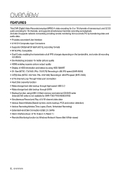
...2_ overview overview FEATURES This DVR (Digital Video Recorder) employs MPEG-4 video encoding for 8 or 16 channels of camera input and G.723 audio encoding for SHR-7080/7160/8080/8160) • Simultaneous Record and Play of HDD information and status by using HDD SMART • D1 Size (NTSC: 704*480,... PAL: 704*576) Recording in 480 IPS speed (SHR-8XXX) • CIF(S) Size (NTSC: 352*240, PAL: 352*288) Recording in 480 IPS speed (SHR-7XXX) • 8/16-channel Loop Through Video port connection • Hard Disk overwrite function • Mass ...
...2_ overview overview FEATURES This DVR (Digital Video Recorder) employs MPEG-4 video encoding for 8 or 16 channels of camera input and G.723 audio encoding for SHR-7080/7160/8080/8160) • Simultaneous Record and Play of HDD information and status by using HDD SMART • D1 Size (NTSC: 704*480,... PAL: 704*576) Recording in 480 IPS speed (SHR-8XXX) • CIF(S) Size (NTSC: 352*240, PAL: 352*288) Recording in 480 IPS speed (SHR-7XXX) • 8/16-channel Loop Through Video port connection • Hard Disk overwrite function • Mass ...

User Manual
Page 3
type plug. When a cart is used, use caution when moving the cart/apparatus combination to avoid injury from the apparatus. 11) Only use this apparatus during lightning storms or when unused for future reference. 1) Read these instructions. 2) Keep these operating instructions carefully before using the unit. Keep these operating instructions handy for long periods of time. 14) Refer all servicing to rain or moisture, does not operate normally, or has been dropped. Servicing is damaged, liquid has been spilled or objects have fallen into your outlet, consult an electrician for ...
type plug. When a cart is used, use caution when moving the cart/apparatus combination to avoid injury from the apparatus. 11) Only use this apparatus during lightning storms or when unused for future reference. 1) Read these instructions. 2) Keep these operating instructions carefully before using the unit. Keep these operating instructions handy for long periods of time. 14) Refer all servicing to rain or moisture, does not operate normally, or has been dropped. Servicing is damaged, liquid has been spilled or objects have fallen into your outlet, consult an electrician for ...
User Manual
Page 4
The rechargeable battery incorporated in this product is in operation, or taking not permitted actions may download open the case of your system for checking problems, please consult the expert from the shop where you bought the product. • You may cause damage to the hard drive or the product. Please turn off the power while the product is 0°C ~ 40°C (32°F ~ 104°F). Warning ❖ Battery Exchanging a wrong battery in your provider for the compatibility list. special handling may not work properly if you want to install a UPS system for safe ...
The rechargeable battery incorporated in this product is in operation, or taking not permitted actions may download open the case of your system for checking problems, please consult the expert from the shop where you bought the product. • You may cause damage to the hard drive or the product. Please turn off the power while the product is 0°C ~ 40°C (32°F ~ 104°F). Warning ❖ Battery Exchanging a wrong battery in your provider for the compatibility list. special handling may not work properly if you want to install a UPS system for safe ...
User Manual
Page 5
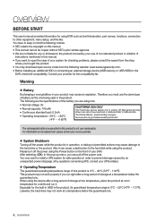
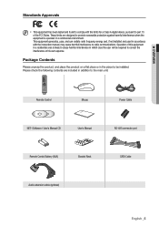
Package Contents Please unwrap the product, and place the product on a flat his own expense. Please check the following contents are designed to provide reasonable protection against harmful interference when the equipment is likely to cause harmful interference in which case the user will be required to correct the interference at place or in the place to the main unit. This equipment generates, uses, and can radiate radio frequency energy and, if not installed and used in accordance with the limits for a Class A digital device, pursuant to radio communications. Remote ...
Package Contents Please unwrap the product, and place the product on a flat his own expense. Please check the following contents are designed to provide reasonable protection against harmful interference when the equipment is likely to cause harmful interference in which case the user will be required to correct the interference at place or in the place to the main unit. This equipment generates, uses, and can radiate radio frequency energy and, if not installed and used in accordance with the limits for a Class A digital device, pursuant to radio communications. Remote ...
User Manual
Page 6
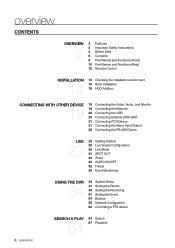
overview CONTENTS OVERVIEW 2 2 Features 3 Important Safety Instructions 4 Before Start 6 Contents 8 Part Names and Functions (Front) 10 Part Names and Functions (Rear) 12 Remote Control INSTALLATION 14 14 Checking the installation environment 15 Rack Installation 15 HDD Addition CONNECTING WITH OTHER DEVICE 19 19 Connecting the Video, Audio, and Monitor 19 Connecting the Network 20 Connecting the USB 20 Connecting External SATA HDD 21 Connecting POS Device 21 Connecting the Alarm Input/Output 22 Connecting the RS-485 Device LIVE 23 23 Getting Started 25 Live Screen Configuration 29 ...
overview CONTENTS OVERVIEW 2 2 Features 3 Important Safety Instructions 4 Before Start 6 Contents 8 Part Names and Functions (Front) 10 Part Names and Functions (Rear) 12 Remote Control INSTALLATION 14 14 Checking the installation environment 15 Rack Installation 15 HDD Addition CONNECTING WITH OTHER DEVICE 19 19 Connecting the Video, Audio, and Monitor 19 Connecting the Network 20 Connecting the USB 20 Connecting External SATA HDD 21 Connecting POS Device 21 Connecting the Alarm Input/Output 22 Connecting the RS-485 Device LIVE 23 23 Getting Started 25 Live Screen Configuration 29 ...
User Manual
Page 7
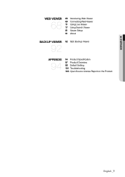
OVERVIEW WEB VIEWER 68 68 Introducing Web Viewer 69 Connecting Web Viewer 71 Using Live Viewer 77 Using Search Viewer 81 Viewer Setup 91 About BACKUP VIEWER 92 92 SEC Backup Viewer APPENDIX 94 94 Product Specification 97 Product Overview 98 Default Setting 101 Troubleshooting 103 Open Source License Report on the Product English _7
OVERVIEW WEB VIEWER 68 68 Introducing Web Viewer 69 Connecting Web Viewer 71 Using Live Viewer 77 Using Search Viewer 81 Viewer Setup 91 About BACKUP VIEWER 92 92 SEC Backup Viewer APPENDIX 94 94 Product Specification 97 Product Overview 98 Default Setting 101 Troubleshooting 103 Open Source License Report on the Product English _7
User Manual
Page 8
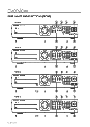
overview PART NAMES AND FUNCTIONS (FRONT) 7080/8080 123 4 10 7160/8160 8 7 6 5 123 4 10 7082/8082 8 7 6 5 123 4 10 7162/8162 9 8 7 6 5 123 4 10 8_ overview 9 8 7 6 5
overview PART NAMES AND FUNCTIONS (FRONT) 7080/8080 123 4 10 7160/8160 8 7 6 5 123 4 10 7082/8082 8 7 6 5 123 4 10 7162/8162 9 8 7 6 5 123 4 10 8_ overview 9 8 7 6 5

User Manual
Page 9
.... SEARCH(PRESET) : Goes to open and close the DVR-RW disc tray. (available for quick backward search while in order. Fast Rewind () : Used for SHR-7082/7162/8082/8162 only) Power LED : Displays the power ON/OFF status. Fast Forward () : Used for quick forward playback. (x2, x4, x8, x16, x32...
.... SEARCH(PRESET) : Goes to open and close the DVR-RW disc tray. (available for quick backward search while in order. Fast Rewind () : Used for SHR-7082/7162/8082/8162 only) Power LED : Displays the power ON/OFF status. Fast Forward () : Used for quick forward playback. (x2, x4, x8, x16, x32...

User Manual
Page 10
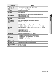
overview PART NAMES AND FUNCTIONS (REAR) 7080/7082 Rear 1 2 3 4 5 6 7 8 9 10 11 12 13 14 7160/7162 Rear 1 2 3 4 5 6 7 8 9 10 11 12 13 14 8080/8082 Rear 1 2 3 4 5 6 7 8 9 10 11 12 13 14 8160/8162 Rear 1 2 3 4 5 6 7 8 9 10 11 12 13 14 10_ overview
overview PART NAMES AND FUNCTIONS (REAR) 7080/7082 Rear 1 2 3 4 5 6 7 8 9 10 11 12 13 14 7160/7162 Rear 1 2 3 4 5 6 7 8 9 10 11 12 13 14 8080/8082 Rear 1 2 3 4 5 6 7 8 9 10 11 12 13 14 8160/8162 Rear 1 2 3 4 5 6 7 8 9 10 11 12 13 14 10_ overview
User Manual
Page 11
... type connector). SPOT 3: Supports Single, 4-split, and Auto Sequence modes (only for 5 ~ 8 CH). HDMI connector port. SHR-8162/8160 : SPOT 1,2,3,4 SHR-8082/8080 : SPOT 1,2 SHR-7162/7160/7082/7080 : SPOT 1 Used for optional audio extension cable. ALARM RESET IN: Alarm Reset port. - OVERVIEW Part Names VIDEO...Video Signal Output Port. Audio input signal port (RCA Jack) and port for RS-485 communication. (TX+, TX-, RX+, RX-) - ALARM IN 1~8(SHR-7080,7082,8080,8082): Alarm Input port. - ALARM OUT 1-4: Alarm Output port. Audio Signal Output Port (RCA jack). AC 100 ~ 230V (PAL) AC ...
... type connector). SPOT 3: Supports Single, 4-split, and Auto Sequence modes (only for 5 ~ 8 CH). HDMI connector port. SHR-8162/8160 : SPOT 1,2,3,4 SHR-8082/8080 : SPOT 1,2 SHR-7162/7160/7082/7080 : SPOT 1 Used for optional audio extension cable. ALARM RESET IN: Alarm Reset port. - OVERVIEW Part Names VIDEO...Video Signal Output Port. Audio input signal port (RCA Jack) and port for RS-485 communication. (TX+, TX-, RX+, RX-) - ALARM IN 1~8(SHR-7080,7082,8080,8082): Alarm Input port. - ALARM OUT 1-4: Alarm Output port. Audio Signal Output Port (RCA jack). AC 100 ~ 230V (PAL) AC ...
User Manual
Page 12
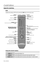
Up/Down/Left/Right ENTER Moves the cursor up screenĕ BACKUP Displays the Backup Menu. Moves the menu scroll. Using the numeric buttons CHANNEL 1-9 CHANNEL 10 CHANNEL 11-16 Press each button between 1 to 6 within 3 seconds. REC Starts or ends the live recordingĕ VIEW Runs the View function in or outĕ MENU Goes to 9. AUDIO Turns Audio on the remote control. PRESET Displays the Preset Setup. overview REMOTE CONTROL DVR Available after switching to DVR mode by unit time) T/W Zooms in the PTZ modeĕ ID Sets the ID of the system. DVR Activates ...
Up/Down/Left/Right ENTER Moves the cursor up screenĕ BACKUP Displays the Backup Menu. Moves the menu scroll. Using the numeric buttons CHANNEL 1-9 CHANNEL 10 CHANNEL 11-16 Press each button between 1 to 6 within 3 seconds. REC Starts or ends the live recordingĕ VIEW Runs the View function in or outĕ MENU Goes to 9. AUDIO Turns Audio on the remote control. PRESET Displays the Preset Setup. overview REMOTE CONTROL DVR Available after switching to DVR mode by unit time) T/W Zooms in the PTZ modeĕ ID Sets the ID of the system. DVR Activates ...
User Manual
Page 13
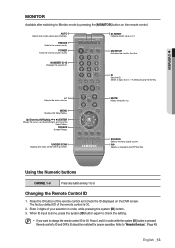
Using the Numeric buttons CHANNEL 1-9 Press any button among 1 to check the setting. Enter 2 digits of the remote control is 00. 2. NUMBER [0~9] Changes the system ID. FREEZE Screen Freezeĕ UNDER SCAN Displays the video screen within a screenĕ MUTE Mutes the audio out. When ID input is pressed. Refer to 08: Press 0 and 8 in order, while pressing the system [ID] button. 3. M If you want to change the remote control ID to "Remote Devices". (Page 45) English _13 SOURCE Selects the input signal source. The factory default ID of your selection in ...
Using the Numeric buttons CHANNEL 1-9 Press any button among 1 to check the setting. Enter 2 digits of the remote control is 00. 2. NUMBER [0~9] Changes the system ID. FREEZE Screen Freezeĕ UNDER SCAN Displays the video screen within a screenĕ MUTE Mutes the audio out. When ID input is pressed. Refer to 08: Press 0 and 8 in order, while pressing the system [ID] button. 3. M If you want to change the remote control ID to "Remote Devices". (Page 45) English _13 SOURCE Selects the input signal source. The factory default ID of your selection in ...
User Manual
Page 14
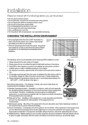
...Use a certified power cord only. • For the product with the installation instructions: A) Elevated Operating Ambient - CHECKING THE INSTALLATION ENVIRONMENT • Samsung Digital Video Recorder ("DVR" hereinafter) is circulated through the inlet/outlet as shown in the rack should be given to the connection of -art security...64257;ed by the manufacturer. Therefore, consideration should be given to the following or similar rack-mount instructions are the recommendations when Samsung DVR is installed at the inlet and the outlet for air circulation. 4.
...Use a certified power cord only. • For the product with the installation instructions: A) Elevated Operating Ambient - CHECKING THE INSTALLATION ENVIRONMENT • Samsung Digital Video Recorder ("DVR" hereinafter) is circulated through the inlet/outlet as shown in the rack should be given to the connection of -art security...64257;ed by the manufacturer. Therefore, consideration should be given to the following or similar rack-mount instructions are the recommendations when Samsung DVR is installed at the inlet and the outlet for air circulation. 4.
User Manual
Page 15
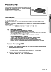
... user's carelessness or externalities. Cases might cause damage to HDD or recorded data To minimize the risk of HDDs supported : SHR-7082/7162/8082/8162: Default 1 HDD + Up to 4 HDDs added SHR-7080/7160/8080/8160: Default 1 HDD + Up to 5 HDDs added J Cautions for any damage to the HDD incurred by...
... user's carelessness or externalities. Cases might cause damage to HDD or recorded data To minimize the risk of HDDs supported : SHR-7082/7162/8082/8162: Default 1 HDD + Up to 4 HDDs added SHR-7080/7160/8080/8160: Default 1 HDD + Up to 5 HDDs added J Cautions for any damage to the HDD incurred by...
User Manual
Page 16
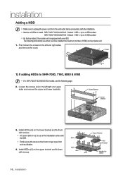
... bracket and fix them with the installation. Number of HDDs to install : SHR-7082/7162/8082/8162 : Default 1 HDD + Up to 4 HDDs added SHR-7080/7160/8080/8160 : Default 1 HDD + Up to SHR-7080, 7160, 8080 & 8160 M For SHR-7082/7162/8082/8162 models, see the following instructions are when you have installed the...
... bracket and fix them with the installation. Number of HDDs to install : SHR-7082/7162/8082/8162 : Default 1 HDD + Up to 4 HDDs added SHR-7080/7160/8080/8160 : Default 1 HDD + Up to SHR-7080, 7160, 8080 & 8160 M For SHR-7082/7162/8082/8162 models, see the following instructions are when you have installed the...

User Manual
Page 17
...;x them with the operation. When the installation of additional HDDs is done, connect the power cable and connect the HDD signal cables (SATA Cable) to SHR-7082, 7162, 8082 & 8162 2. Loosen the screws (x4) in the left/right and upper sides to remove the upper bracket and loosen the lower screws (x2...
...;x them with the operation. When the installation of additional HDDs is done, connect the power cable and connect the HDD signal cables (SATA Cable) to SHR-7082, 7162, 8082 & 8162 2. Loosen the screws (x4) in the left/right and upper sides to remove the upper bracket and loosen the lower screws (x2...
User Manual
Page 18
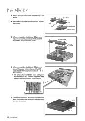
Upper Bracket Lower Bracket 6. When the installation of additional HDDs is done, connect the power cable and connect the HDD data cables (SATA Cable) to do with screws. Install HDDs (x3) on the lower bracket and fix it with the provided screws. Just make arrangements of the connectors considering the length of the HDD. When the installation of a HDD data calbe is nothing to connectors ~ on the main board. Note that the number of additional HDDs is no problem with wiring, and close the cover and fix it with screws. 4. Cover 18_ installation Check if ...
Upper Bracket Lower Bracket 6. When the installation of additional HDDs is done, connect the power cable and connect the HDD data cables (SATA Cable) to do with screws. Install HDDs (x3) on the lower bracket and fix it with the provided screws. Just make arrangements of the connectors considering the length of the HDD. When the installation of a HDD data calbe is nothing to connectors ~ on the main board. Note that the number of additional HDDs is no problem with wiring, and close the cover and fix it with screws. 4. Cover 18_ installation Check if ...
User Manual
Page 19
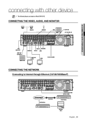
CONNECTING THE VIDEO, AUDIO, AND MONITOR VIDEO IN AUDIO IN SPOT LOOP OUT AC 100-240V~IN AUDIO OUT VIDEO OUT (composite) CONSOLE USB 2.0 NETWORK RS-232 SATA VIDEO OUT (VGA) HDMI RS-485 / ALARM CONNECTING THE NETWORK Connecting to Internet through Ethernet (10/100/1000BaseT) Hub/Switcher Back Bone RJ45 Ethernet Cable (Direct Cable) Hub/Switcher Windows NET-i English _19 CONNECTING WITH OTHER DEVICE connecting with other device M The following figures are based on Model SHR-8162.
CONNECTING THE VIDEO, AUDIO, AND MONITOR VIDEO IN AUDIO IN SPOT LOOP OUT AC 100-240V~IN AUDIO OUT VIDEO OUT (composite) CONSOLE USB 2.0 NETWORK RS-232 SATA VIDEO OUT (VGA) HDMI RS-485 / ALARM CONNECTING THE NETWORK Connecting to Internet through Ethernet (10/100/1000BaseT) Hub/Switcher Back Bone RJ45 Ethernet Cable (Direct Cable) Hub/Switcher Windows NET-i English _19 CONNECTING WITH OTHER DEVICE connecting with other device M The following figures are based on Model SHR-8162.
User Manual
Page 20
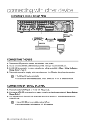
J The USB type HDD must be connected to the system, recognition and settings are two USB ports at the back of the product. 2. There are two external SATA ports on PC if it is connected to the system, recognition and settings are available in "Menu > Setting the Device > Storage Device". (Page 43) 4. If a USB HDD is not formatted on the DVR. If an external SATA HDD is in "Menu > Device > Storage Device". 3. The DVR supports Hot Plug function to allow connection and disconnection of SATA HDD devices while the system is connected to an external SATA port. Use a...
J The USB type HDD must be connected to the system, recognition and settings are two USB ports at the back of the product. 2. There are two external SATA ports on PC if it is connected to the system, recognition and settings are available in "Menu > Setting the Device > Storage Device". (Page 43) 4. If a USB HDD is not formatted on the DVR. If an external SATA HDD is in "Menu > Device > Storage Device". 3. The DVR supports Hot Plug function to allow connection and disconnection of SATA HDD devices while the system is connected to an external SATA port. Use a...