Service Manual
Page 2
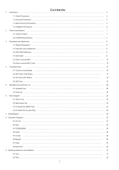
... ...20 5-2 Parts List ...22 6. Wiring Diagram ...34 8. Schematic Diagrams ...27 8-1 DC- Troubleshooting ...16 4-1 Common Acknowledge ...16 4-2 No Picture (VGA Mode) ... 17 4-3 No Picture (DVI Mode) ... 18 4-4 No Power ... 19 5. DC ...27 8-2 Input ...27 8-3 TSUMU58WHJ ...28 8-4 Power ...28 8-5 Inverter ...29 8-6 Keypad ...29 8-7 Audio ... 30 8-8 Ear Phone ...30 9. Product specifications ...7 2-1 Fashion Feature ...7 2-2 2220WM Specifications ...7 3. Block...
... ...20 5-2 Parts List ...22 6. Wiring Diagram ...34 8. Schematic Diagrams ...27 8-1 DC- Troubleshooting ...16 4-1 Common Acknowledge ...16 4-2 No Picture (VGA Mode) ... 17 4-3 No Picture (DVI Mode) ... 18 4-4 No Power ... 19 5. DC ...27 8-2 Input ...27 8-3 TSUMU58WHJ ...28 8-4 Power ...28 8-5 Inverter ...29 8-6 Keypad ...29 8-7 Audio ... 30 8-8 Ear Phone ...30 9. Product specifications ...7 2-1 Fashion Feature ...7 2-2 2220WM Specifications ...7 3. Block...
Service Manual
Page 3
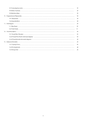
Disassembly and Reassembly ...36 10-1 Disassembly ...36 10-2 Assembly Block ...39 11. Circuit Descriptions ...42 12-1 Overall Block Structture ...42 12-2 IP Board Part (Power) Schematic Diagrams ...44 12-3 IP Board (Inverter) Schematic Diagrams ...45 13. 9-3 Connecting the monitor ...33 9-4 Monitor Assembly ... 34 9-5 Attaching a Base ... 35 10. Reference Information ...46 13-1 Technical Terms ...46 13-2 Pin Assignments ...48 13-3 Timing Chart ...49 3 PCB Diagram ...40 11-1 Mian Board...40 12-2 Power Board...41 12.
Disassembly and Reassembly ...36 10-1 Disassembly ...36 10-2 Assembly Block ...39 11. Circuit Descriptions ...42 12-1 Overall Block Structture ...42 12-2 IP Board Part (Power) Schematic Diagrams ...44 12-3 IP Board (Inverter) Schematic Diagrams ...45 13. 9-3 Connecting the monitor ...33 9-4 Monitor Assembly ... 34 9-5 Attaching a Base ... 35 10. Reference Information ...46 13-1 Technical Terms ...46 13-2 Pin Assignments ...48 13-3 Timing Chart ...49 3 PCB Diagram ...40 11-1 Mian Board...40 12-2 Power Board...41 12.
Service Manual
Page 4
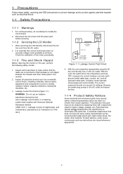
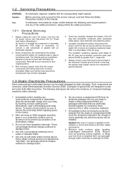
...nonmetallic control knobs, insulating materials, cabinet backs, adjustment and compartment covers or shields, isolation resistor- When servicing the LCD Monitor, Disconnect the AC line cord from visual inspection. A substitute replacement that does not have an accurate voltage meter ...user, perform the following safety checks: 1. Parts that complies with components rated for Appliances), and Underwriters Laboratories (UL Publication UL1410, 59.7). Disconnect the AC power and DC power jack before servicing. 1-1-2 Servicing the LCD Monitor 1. Use a leakage current tester or a ...
...nonmetallic control knobs, insulating materials, cabinet backs, adjustment and compartment covers or shields, isolation resistor- When servicing the LCD Monitor, Disconnect the AC line cord from visual inspection. A substitute replacement that does not have an accurate voltage meter ...user, perform the following safety checks: 1. Parts that complies with components rated for Appliances), and Underwriters Laboratories (UL Publication UL1410, 59.7). Disconnect the AC power and DC power jack before servicing. 1-1-2 Servicing the LCD Monitor 1. Use a leakage current tester or a ...
Service Manual
Page 5
...body by touching a known earth ground. If unforeseen circumstances create conflict between the blades of the AC plug and accessible conductive parts (see above the printed circuit board for safety. Make sure that the screws, components and wiring have been correctly reinstalled....soldering iron to damage ESDs. 6. Most replacement ESDs are ready to install it on a conductive surface such as aluminum foil to the monitor. 2. Minimize body motions when handling unpackaged replacement ESDs. Alternatively, wear a discharging wrist-strap device. Motions such as "anti-static" can...
...body by touching a known earth ground. If unforeseen circumstances create conflict between the blades of the AC plug and accessible conductive parts (see above the printed circuit board for safety. Make sure that the screws, components and wiring have been correctly reinstalled....soldering iron to damage ESDs. 6. Most replacement ESDs are ready to install it on a conductive surface such as aluminum foil to the monitor. 2. Minimize body motions when handling unpackaged replacement ESDs. Alternatively, wear a discharging wrist-strap device. Motions such as "anti-static" can...
Service Manual
Page 16
... LCM support more than 30 timing modes, if the input timing mode is an abnormal color that means the problem happen in the digital circuit part. 4 Troubleshooting 4-1 Common Acknowledge If you change the interface board, be sure that stand the problem happen in the analog circuit... part, if only some scale appears abnormal color that the U104 and U105 these two components also changed to the new I/F board because there was program ...
... LCM support more than 30 timing modes, if the input timing mode is an abnormal color that means the problem happen in the digital circuit part. 4 Troubleshooting 4-1 Common Acknowledge If you change the interface board, be sure that stand the problem happen in the analog circuit... part, if only some scale appears abnormal color that the U104 and U105 these two components also changed to the new I/F board because there was program ...
Service Manual
Page 42
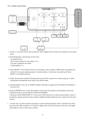
...: I2C is controlled by the A/D converter of the chip. Scaler: Receives the analog R,G,B signals and convert them to the old serial systems. 7. 12-1-2 Main board Parts TSUM16AWK-LF-1 (PC)ANALOG R G B HSYNC Display Response LVDS P Processing Time Panel A Single Interface Engine Enhancement Interface N Engine SDRAM E L OSD Clock MCU Generator Function Key 3.3V...
...: I2C is controlled by the A/D converter of the chip. Scaler: Receives the analog R,G,B signals and convert them to the old serial systems. 7. 12-1-2 Main board Parts TSUM16AWK-LF-1 (PC)ANALOG R G B HSYNC Display Response LVDS P Processing Time Panel A Single Interface Engine Enhancement Interface N Engine SDRAM E L OSD Clock MCU Generator Function Key 3.3V...
Service Manual
Page 43
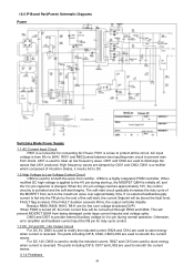
... a rectifier which composed of the soft-start begins. When the Vcc pin voltage reaches approximately 10V, the control circuitry is from shock. The parts including C815, C817 and L802 are used to smooth the current waves. 3.1.4 Feedback 44 AC input voltage is activated and the soft-start ...the HV pin during normal operation. Otherwise, error amplifier and feedback current input the FB pin for connecting AC Power. 12-2 IP Board Part(Power) Schematic Diagrams Power Switching Mode Power Supply 1.1 AC Current Input Circuit P801 is reversed. C801 and C802 are used to discharge ...
... a rectifier which composed of the soft-start begins. When the Vcc pin voltage reaches approximately 10V, the control circuitry is from shock. The parts including C815, C817 and L802 are used to smooth the current waves. 3.1.4 Feedback 44 AC input voltage is activated and the soft-start ...the HV pin during normal operation. Otherwise, error amplifier and feedback current input the FB pin for connecting AC Power. 12-2 IP Board Part(Power) Schematic Diagrams Power Switching Mode Power Supply 1.1 AC Current Input Circuit P801 is reversed. C801 and C802 are used to discharge ...
Service Manual
Page 44
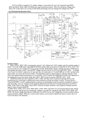
... LCT pin is supplied 2.5-v stable voltage. The operation frequency determined by using a resistor divider(R507, R516), change the voltage from T801. 12-3 IP Board Part(Inverter Part) Inverter Circuit 1. Turning each transformer driving two lamps in drain of SST. R528, R533 are connected in parallel with each NChannel MOSFET "on " duration of...
... LCT pin is supplied 2.5-v stable voltage. The operation frequency determined by using a resistor divider(R507, R516), change the voltage from T801. 12-3 IP Board Part(Inverter Part) Inverter Circuit 1. Turning each transformer driving two lamps in drain of SST. R528, R533 are connected in parallel with each NChannel MOSFET "on " duration of...


