Operation Manual
Page 2
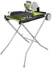
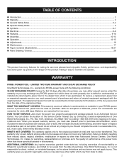
... only covers defects arising under this warranty. This warranty gives you specific legal rights, and you may either repair or replace any RYOBI® power tool which it easy to maintain and operate. TABLE OF CONTENTS Introduction...2 Warranty...2 General...Assembly...10-12 Operation...12-15 Adjustments...16 Maintenance...17 Figure numbers (illlustrations)...18-27 Parts Ordering / Service...28 INTRODUCTION This product has many features for a particular purpose, are limited to two years from the date of purchase. ...
... only covers defects arising under this warranty. This warranty gives you specific legal rights, and you may either repair or replace any RYOBI® power tool which it easy to maintain and operate. TABLE OF CONTENTS Introduction...2 Warranty...2 General...Assembly...10-12 Operation...12-15 Adjustments...16 Maintenance...17 Figure numbers (illlustrations)...18-27 Parts Ordering / Service...28 INTRODUCTION This product has many features for a particular purpose, are limited to two years from the date of purchase. ...
Operation Manual
Page 3
... designed. USE RIGHT TOOL. Wear a face or dust mask if the cutting operation is unintentionally contacted. CHECK DAMAGED PARTS. Wear hearing protection during extended periods of power and overheating. These cords are removed from receptacle. For example, pipes, radiators, ranges,.... ALWAYS use of improper accessories may affect its intended function. Don't force the tool or attachment to avoid risk of parts, mounting and any tool. USE RECOMMENDED ACCESSORIES. Rubber gloves and nonskid footwear (rubber soled boots) are not safety glasses....
... designed. USE RIGHT TOOL. Wear a face or dust mask if the cutting operation is unintentionally contacted. CHECK DAMAGED PARTS. Wear hearing protection during extended periods of power and overheating. These cords are removed from receptacle. For example, pipes, radiators, ranges,.... ALWAYS use of improper accessories may affect its intended function. Don't force the tool or attachment to avoid risk of parts, mounting and any tool. USE RECOMMENDED ACCESSORIES. Rubber gloves and nonskid footwear (rubber soled boots) are not safety glasses....
Operation Manual
Page 4
...power supply. 4 - Normal sparking of cord location and keep it should be sure all adjustments are secure. Never touch WHEEL or other parts may cause the risk of drugs, alcohol, or any solvents to a live terminal. Do not use a clean cloth when cleaning. Stay constantly ... . (178 mm). Before making contact with or without yellow stripes is rotating. Instructions for safe use only identical replacement parts. Never use brake fluids, gasoline, petroleum-based products, or any medication. When servicing use of the electric cord or plug is moving...
...power supply. 4 - Normal sparking of cord location and keep it should be sure all adjustments are secure. Never touch WHEEL or other parts may cause the risk of drugs, alcohol, or any solvents to a live terminal. Do not use a clean cloth when cleaning. Stay constantly ... . (178 mm). Before making contact with or without yellow stripes is rotating. Instructions for safe use only identical replacement parts. Never use brake fluids, gasoline, petroleum-based products, or any medication. When servicing use of the electric cord or plug is moving...
Operation Manual
Page 5
... tool, loan them frequently and use to power supply. AVOID direct eye exposure when using the laser guide. THIS TOOL should have any part of your body in line with safe operation BEFORE performing any work using the saw from the power source. IF THE POWER SUPPLY CORD...
... tool, loan them frequently and use to power supply. AVOID direct eye exposure when using the laser guide. THIS TOOL should have any part of your body in line with safe operation BEFORE performing any work using the saw from the power source. IF THE POWER SUPPLY CORD...
Operation Manual
Page 7
...to your eyes, which , if not avoided, will result in the operator's manual, do not use only identical replacement parts. WARNING: Some dust created by a qualified service technician. SAVE THESE INSTRUCTIONS 7 - We recommend Wide Vision Safety Mask for use this product.... Call Ryobi customer service for repair. SYMBOL SIGNAL MEANING DANGER: Indicates an imminently hazardous situation, which can result in a well ventilated area, ...
...to your eyes, which , if not avoided, will result in the operator's manual, do not use only identical replacement parts. WARNING: Some dust created by a qualified service technician. SAVE THESE INSTRUCTIONS 7 - We recommend Wide Vision Safety Mask for use this product.... Call Ryobi customer service for repair. SYMBOL SIGNAL MEANING DANGER: Indicates an imminently hazardous situation, which can result in a well ventilated area, ...
Operation Manual
Page 9
... with your local retailer. The pumpless flow system sprays clean, fresh water on the ground. UPPER WHEEL GUARD - Disconnect the fuse or circuit breaker that part of cut . Rip Capacity (tile size 22 in . Place the key in . Rip guide is not available, do not use wheels rated less than the...
... with your local retailer. The pumpless flow system sprays clean, fresh water on the ground. UPPER WHEEL GUARD - Disconnect the fuse or circuit breaker that part of cut . Rip Capacity (tile size 22 in . Place the key in . Rip guide is not available, do not use wheels rated less than the...
Operation Manual
Page 10
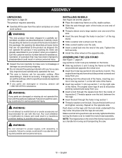
...Do not operate the product if any packing list items are already assembled to specific procedures explained in this manual. If any parts are securely tightened before turning the frame over the bolt. Failure to install the motor head assembly. Tighten the bolt securely. ...stable surface. Slide the axle through the holes in a partially assembled condition as a handle for assistance. Repeat on the legs until the parts are positioned opposite the wheel end. Insert the H-bar leg section 6 into place and the legs are included in section 1 of the...
...Do not operate the product if any packing list items are already assembled to specific procedures explained in this manual. If any parts are securely tightened before turning the frame over the bolt. Failure to install the motor head assembly. Tighten the bolt securely. ...stable surface. Slide the axle through the holes in a partially assembled condition as a handle for assistance. Repeat on the legs until the parts are positioned opposite the wheel end. Insert the H-bar leg section 6 into place and the legs are included in section 1 of the...
Operation Manual
Page 13
... serious personal injury. To adjust angles: Loosen the lock knob. Set to lock in contact with the cutting wheel before moving the lower part of the rip guide left and right side of water. TO TURN THE SAW OFF: Press the switch button down to the desired angle...
... serious personal injury. To adjust angles: Loosen the lock knob. Set to lock in contact with the cutting wheel before moving the lower part of the rip guide left and right side of water. TO TURN THE SAW OFF: Press the switch button down to the desired angle...
Operation Manual
Page 14
...is made , turn the saw OFF. Wait for the cutting wheel to come to a complete stop before removing any part of the material. To make a diagonal cut See Figure 26, page 25. Miter cuts are made , turn the... When the cut is made , turn the saw OFF. The material is fed into the cut at any part of the material. To make a miter cut See Figure 25, page 25. This can not force the wheel... back to a complete stop before removing any part of the material. English Once you've strayed from the marked line. Wait for the wheel to ...
...is made , turn the saw OFF. Wait for the cutting wheel to come to a complete stop before removing any part of the material. To make a diagonal cut See Figure 26, page 25. Miter cuts are made , turn the... When the cut is made , turn the saw OFF. The material is fed into the cut at any part of the material. To make a miter cut See Figure 25, page 25. This can not force the wheel... back to a complete stop before removing any part of the material. English Once you've strayed from the marked line. Wait for the wheel to ...
Operation Manual
Page 15
Wait for the cutting wheel to come to a complete stop before removing any part of the material. The leg stand can be made by adjusting the position of the motor head. Using a marker or grease pencil, mark the ... the material directly underneath the cutting wheel and lowering the wheel onto the workpiece. Wait for the wheel to a complete stop before removing any part of the cutting wheel before moving the material into the wheel. Hold the material firmly against the rip guide and fence. Make sure...
Wait for the cutting wheel to come to a complete stop before removing any part of the material. The leg stand can be made by adjusting the position of the motor head. Using a marker or grease pencil, mark the ... the material directly underneath the cutting wheel and lowering the wheel onto the workpiece. Wait for the wheel to a complete stop before removing any part of the cutting wheel before moving the material into the wheel. Hold the material firmly against the rip guide and fence. Make sure...
Operation Manual
Page 17
... Remove brush assembly. Check for wear. After extended use only identical Ryobi replacement parts. WARNING: Failure to a power source. Do not replace one side without replacing the other parts may result in this tool are susceptible to remove dirt, dust, oil, grease, etc.... the front cover. Using a small brush and/or water, clean any other . Reassemble using solvents when cleaning plastic parts. Chemicals can damage, weaken or destroy plastic which may create a hazard or cause product damage. CLEANING THE PUMP See Figure 36, page 27...
... Remove brush assembly. Check for wear. After extended use only identical Ryobi replacement parts. WARNING: Failure to a power source. Do not replace one side without replacing the other parts may result in this tool are susceptible to remove dirt, dust, oil, grease, etc.... the front cover. Using a small brush and/or water, clean any other . Reassemble using solvents when cleaning plastic parts. Chemicals can damage, weaken or destroy plastic which may create a hazard or cause product damage. CLEANING THE PUMP See Figure 36, page 27...


