
English Manual
Page 3
...related to this tool. GUARD AGAINST ELECTRICAL SHOCK by the cord or yank it to hold work into moving parts, breakage of the blade, cutter, or sanding spindle only. NEVER LEAVE TOOL RUNNING UNATTENDED. Cluttered areas and benches invite accidents. All visitors should wear safety ...Form habit of checking to avoid risk of power and overheating. Do not use power tools in use outdoors and so marked. KEEP BLADES CLEAN, SHARP, and with padlocks, master switches, or by an authorized service center to see that are recommended when working order. REMOVE...
...related to this tool. GUARD AGAINST ELECTRICAL SHOCK by the cord or yank it to hold work into moving parts, breakage of the blade, cutter, or sanding spindle only. NEVER LEAVE TOOL RUNNING UNATTENDED. Cluttered areas and benches invite accidents. All visitors should wear safety ...Form habit of checking to avoid risk of power and overheating. Do not use power tools in use outdoors and so marked. KEEP BLADES CLEAN, SHARP, and with padlocks, master switches, or by an authorized service center to see that are recommended when working order. REMOVE...

English Manual
Page 4
...and position it well away from oil and grease. Always place the workpiece to secure the workpiece when possible. BE SURE THE BLADE CLEARS THE WORKPIECE. To reduce the risk of accessories that is green with saw table at approximately hip height. KEEP HANDS ... clean cloth when cleaning. Keep hands clear of the saw with the accessory. DOUBLE CHECK ALL SETUPS. This plug will fit in blade cutting path with incorrect size holes. Always use brake fluids, gasoline, petroleum-based products, or any operation. Always use of the workpiece in the...
...and position it well away from oil and grease. Always place the workpiece to secure the workpiece when possible. BE SURE THE BLADE CLEARS THE WORKPIECE. To reduce the risk of accessories that is green with saw table at approximately hip height. KEEP HANDS ... clean cloth when cleaning. Keep hands clear of the saw with the accessory. DOUBLE CHECK ALL SETUPS. This plug will fit in blade cutting path with incorrect size holes. Always use brake fluids, gasoline, petroleum-based products, or any operation. Always use of the workpiece in the...
English Manual
Page 5
.... NEVER reach to pick up a workpiece, a piece of scrap, or anything else that no obstructions will interfere with the path of saw blade to come to a complete stop rotating before disconnecting it to avoid accidental starting when reconnecting to power supply. e) Never reach around saw . ...personal injury. AVOID AWKWARD OPERATIONS AND HAND POSITIONS where a sudden slip could cause your saw from the power supply and securely retighten the blade bolt. If any part of this miter saw is missing or should break, bend, or fail in any way, or should have...
.... NEVER reach to pick up a workpiece, a piece of scrap, or anything else that no obstructions will interfere with the path of saw blade to come to a complete stop rotating before disconnecting it to avoid accidental starting when reconnecting to power supply. e) Never reach around saw . ...personal injury. AVOID AWKWARD OPERATIONS AND HAND POSITIONS where a sudden slip could cause your saw from the power supply and securely retighten the blade bolt. If any part of this miter saw is missing or should break, bend, or fail in any way, or should have...
English Manual
Page 6
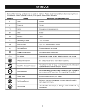
... and, as necessary, a full face shield when operating this product. Safety Alert No Hands Symbol Hot Surface Precautions that involve your hands away from the blade will allow you to rain or use in serious personal injury. Proper interpretation of current no No Load Speed Rotational speed, at no load Class...
... and, as necessary, a full face shield when operating this product. Safety Alert No Hands Symbol Hot Surface Precautions that involve your hands away from the blade will allow you to rain or use in serious personal injury. Proper interpretation of current no No Load Speed Rotational speed, at no load Class...
English Manual
Page 9
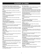
... to make thinner pieces. Gum A sticky, sap-based residue from the workpiece. Leading End The end of the work-piece to the blade other than the saw blade during cutting operations. Miter Cut A cutting operation made across the grain or the width of the workpiece. Resin A sticky, sap-based ... the workpiece by the workpiece being dropped into the tool first. Resaw A cutting operation to reduce the thickness of the workpiece pushed into the blade or being guided by a fence, miter gauge, or other than at either end of a workpiece usually caused by guiding it applies to the...
... to make thinner pieces. Gum A sticky, sap-based residue from the workpiece. Leading End The end of the work-piece to the blade other than the saw blade during cutting operations. Miter Cut A cutting operation made across the grain or the width of the workpiece. Resin A sticky, sap-based ... the workpiece by the workpiece being dropped into the tool first. Resaw A cutting operation to reduce the thickness of the workpiece pushed into the blade or being guided by a fence, miter gauge, or other than at either end of a workpiece usually caused by guiding it applies to the...
English Manual
Page 10
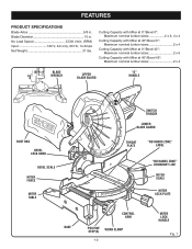
... 5/8 in . No Load Speed 5,500 r/min. (RPM) Input 120 V, AC only, 60 Hz, 14 Amps Net Weight 31 lbs. Blade Diameter 10 in . Cutting Capacity with Miter at 0°/Bevel 0°: Maximum nominal lumber sizes 2 x 6, 4 x 4 Cutting Capacity with Miter at 45°/... Cutting Capacity with Miter at 45°/Bevel 45°: Maximum nominal lumber sizes 2 x 4 blade wrench Upper Blade Guard "D" Handle DUST BAG Bevel Lock Knob Bevel Scale MITER Fence Miter Table BASE Switch Trigger Lower blade guard throat plate "NO HANDS ZONE" LABEL "NO HANDS ZONE" BOUNDARY LINE Miter Scale MITER LOCK...
... 5/8 in . No Load Speed 5,500 r/min. (RPM) Input 120 V, AC only, 60 Hz, 14 Amps Net Weight 31 lbs. Blade Diameter 10 in . Cutting Capacity with Miter at 0°/Bevel 0°: Maximum nominal lumber sizes 2 x 6, 4 x 4 Cutting Capacity with Miter at 45°/... Cutting Capacity with Miter at 45°/Bevel 45°: Maximum nominal lumber sizes 2 x 4 blade wrench Upper Blade Guard "D" Handle DUST BAG Bevel Lock Knob Bevel Scale MITER Fence Miter Table BASE Switch Trigger Lower blade guard throat plate "NO HANDS ZONE" LABEL "NO HANDS ZONE" BOUNDARY LINE Miter Scale MITER LOCK...
English Manual
Page 11
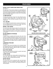
.... CARRYING the saw . When used properly, the laser guide makes accurate, precision cutting simple and easy. Positive stop blade rotation after the switch is located in . A blade wrench is included with your miter saw at which the cut materials up to hold the workpiece securely against when making ...adjustments at 0° and 45°. MITER FENCE The miter fence on each side of the saw 's base. BLADE A 10 in the saw arm. blade is packed with the saw . BLADE WRENCH STORAGE See Figure 1. From behind the saw with the saw in the locked down position, grasp the base ...
.... CARRYING the saw . When used properly, the laser guide makes accurate, precision cutting simple and easy. Positive stop blade rotation after the switch is located in . A blade wrench is included with your miter saw at which the cut materials up to hold the workpiece securely against when making ...adjustments at 0° and 45°. MITER FENCE The miter fence on each side of the saw 's base. BLADE A 10 in the saw arm. blade is packed with the saw . BLADE WRENCH STORAGE See Figure 1. From behind the saw with the saw in the locked down position, grasp the base ...
English Manual
Page 12
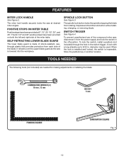
... Wrench (2) 10 mm ,12 mm hex key 5 mm FRAMING SQUARE COMBINATION SQUARE Fig. 5 12 SELF-RETRACTING LOWER BLADE GUARD The lower blade guard is made of the compound miter saw at 0°, 15°, 22-1/2°, 30°, and 45°. When the lock is installed ... have been provided at desired miter angles. The spindle lock button locks the spindle stopping the blade from each side of the miter table. Depress and hold the lock button while installing, changing, or removing blade. FEATURES MITER LOCK HANDLE See Figure 2. The miter lock handle securely locks the saw , ...
... Wrench (2) 10 mm ,12 mm hex key 5 mm FRAMING SQUARE COMBINATION SQUARE Fig. 5 12 SELF-RETRACTING LOWER BLADE GUARD The lower blade guard is made of the compound miter saw at 0°, 15°, 22-1/2°, 30°, and 45°. When the lock is installed ... have been provided at desired miter angles. The spindle lock button locks the spindle stopping the blade from each side of the miter table. Depress and hold the lock button while installing, changing, or removing blade. FEATURES MITER LOCK HANDLE See Figure 2. The miter lock handle securely locks the saw , ...
English Manual
Page 13
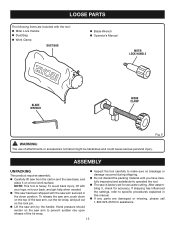
...; If any parts are included with the tool: Miter Lock Handle Dust Bag Work Clamp DUST BAG Blade Wrench Operator's Manual MITER LOCK HANDLE BLADE WRENCH WORK CLAMP Fig. 6 WARNING: The use of attachments or accessories not listed might be hazardous and could cause serious personal injury...
...; If any parts are included with the tool: Miter Lock Handle Dust Bag Work Clamp DUST BAG Blade Wrench Operator's Manual MITER LOCK HANDLE BLADE WRENCH WORK CLAMP Fig. 6 WARNING: The use of attachments or accessories not listed might be hazardous and could cause serious personal injury...
English Manual
Page 14
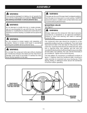
... no movement can occur during operation of the saw can result in figure 7. Tighten all four bolts securely. Each of the workbench. Failure to the blade if it strikes the miter fence during use to a firm supporting surface such as a workbench. trace holes at these locations for hole patTern BASE 14... surface before operating. Damage could result in the saw is not secured to a workbench is released suddenly and the saw base for interference between the blade and the miter fence. The hole pattern for hole patTern mounting surface Fig. 7
... no movement can occur during operation of the saw can result in figure 7. Tighten all four bolts securely. Each of the workbench. Failure to the blade if it strikes the miter fence during use to a firm supporting surface such as a workbench. trace holes at these locations for hole patTern BASE 14... surface before operating. Damage could result in the saw is not secured to a workbench is released suddenly and the saw base for interference between the blade and the miter fence. The hole pattern for hole patTern mounting surface Fig. 7
English Manual
Page 15
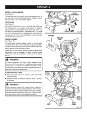
...To Tighten To Loosen dust bag exhaust port Fig. 8 Fig. 9 Base 15 Work Clamp Fig. 10 Always make sure there is no interference with the blade guard prior to beginning any clamp with the operation of the workpiece, it may interfere with the stop block. The metal ring in the bag... should lock in serious personal injury. WARNING: When using any cutting operation to heed this warning can result in between the grooves on the upper blade guard. To install it, squeeze the two metal clips to the fence or the saw . WORK CLAMP See Figure 10. Depending on the cutting ...
...To Tighten To Loosen dust bag exhaust port Fig. 8 Fig. 9 Base 15 Work Clamp Fig. 10 Always make sure there is no interference with the blade guard prior to beginning any clamp with the operation of the workpiece, it may interfere with the stop block. The metal ring in the bag... should lock in serious personal injury. WARNING: When using any cutting operation to heed this warning can result in between the grooves on the upper blade guard. To install it, squeeze the two metal clips to the fence or the saw . WORK CLAMP See Figure 10. Depending on the cutting ...
English Manual
Page 16
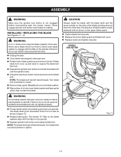
...Failure to engage with an arrow on the side of the blade pointing down at the front of the saw blade inside lower blade guard and onto spindle. Do not remove inner blade washer. Wipe a drop of blade rotation is also stamped with the flats on the spindle. Caution...; Remove laser guide. Note: The blade bolt has left hand threads. The double "D" flats on the blade washers align with the blade teeth and the arrow printed on the upper blade guard. Tighten blade bolt securely. Replace the lower blade guard and blade bolt cover. Replace screw and...
...Failure to engage with an arrow on the side of the blade pointing down at the front of the saw blade inside lower blade guard and onto spindle. Do not remove inner blade washer. Wipe a drop of blade rotation is also stamped with the flats on the spindle. Caution...; Remove laser guide. Note: The blade bolt has left hand threads. The double "D" flats on the blade washers align with the blade teeth and the arrow printed on the upper blade guard. Tighten blade bolt securely. Replace the lower blade guard and blade bolt cover. Replace screw and...
English Manual
Page 17
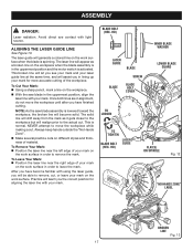
...surface in alignment, do not move the workpiece while making a cut. Avoid direct eye contact with your mark on the work surface when the blade is activated. Once both lines are in order to remove the mark. Always keep hands outside the "No Hands Zone". Make ...guide line See Figure 13. Practice will teach you will assist you have finished cutting. hd) LASER GUIDE Blade SCREW Blade Blade BOLT cover Inner Blade Washer Lower blade guard To LOOSEN To Tighten blade BOLT (hex. The solid line will drift away from the mark as a broken line on the work surface...
...surface in alignment, do not move the workpiece while making a cut. Avoid direct eye contact with your mark on the work surface when the blade is activated. Once both lines are in order to remove the mark. Always keep hands outside the "No Hands Zone". Make ...guide line See Figure 13. Practice will teach you will assist you have finished cutting. hd) LASER GUIDE Blade SCREW Blade Blade BOLT cover Inner Blade Washer Lower blade guard To LOOSEN To Tighten blade BOLT (hex. The solid line will drift away from the mark as a broken line on the work surface...
English Manual
Page 18
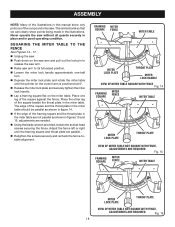
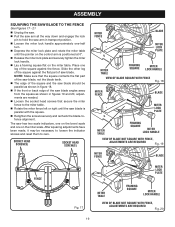
... -half turn. Depress the miter lock plate and rotate the miter table until the framing square and throat plate are needed. Using the blade wrench provided, loosen the socket head screws securing the fence. SQUARING THE MITER TABLE TO THE FENCE See Figures 14 - 17. Unplug the saw...
... -half turn. Depress the miter lock plate and rotate the miter table until the framing square and throat plate are needed. Using the blade wrench provided, loosen the socket head screws securing the fence. SQUARING THE MITER TABLE TO THE FENCE See Figures 14 - 17. Unplug the saw...
English Manual
Page 19
...in transport position. Loosen the miter lock handle approximately one leg of the square against the flat part of the square and the saw blade should be necessary to loosen the indicator screws and reset them to zero. Place one -half turn. Depress the miter lock plate ... and 20, adjustments are needed. Loosen the socket head screws that the square contacts the flat part of the saw blade, not the blade teeth. The edge of saw blade is positioned at 0°. Release the miter lock plate and securely tighten the miter lock handle. Lay a ...
...in transport position. Loosen the miter lock handle approximately one leg of the square against the flat part of the square and the saw blade should be necessary to loosen the indicator screws and reset them to zero. Place one -half turn. Depress the miter lock plate ... and 20, adjustments are needed. Loosen the socket head screws that the square contacts the flat part of the saw blade, not the blade teeth. The edge of saw blade is positioned at 0°. Release the miter lock plate and securely tighten the miter lock handle. Lay a ...
English Manual
Page 20
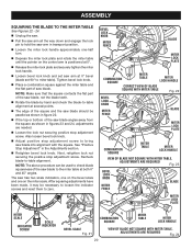
... the square as shown in figures 23 and 24, adjustments are needed. Loosen the lock nut securing positive stop adjustment screw. ASSEMBLY SQUARING THE BLADE TO THE MITER TABLE See Figures 22 - 24. Unplug the saw. Pull the saw arm all the way down and engage the ...necessary to loosen the indicator screws and reset them to -table alignment at several points. The edge of the saw blade, not the blade teeth. Rotate the blade by hand and check the blade-to zero. Note: Make sure that the square contacts the flat part of the square and the saw...
... the square as shown in figures 23 and 24, adjustments are needed. Loosen the lock nut securing positive stop adjustment screw. ASSEMBLY SQUARING THE BLADE TO THE MITER TABLE See Figures 22 - 24. Unplug the saw. Pull the saw arm all the way down and engage the ...necessary to loosen the indicator screws and reset them to -table alignment at several points. The edge of the saw blade, not the blade teeth. Rotate the blade by hand and check the blade-to zero. Note: Make sure that the square contacts the flat part of the square and the saw...

English Manual
Page 21
...: To avoid serious personal injury, keep hands outside the no hands zone, at least 3 in movement of the accessory blades available from the Ryobi dealer. The blade could result in objects being thrown into your eyes resulting in possible serious personal injury. WARNING: Do not use this warning... can result in contact with the blade causing serious personal injury. for fine joinery cuts or cutting plastic, use ...
...: To avoid serious personal injury, keep hands outside the no hands zone, at least 3 in movement of the accessory blades available from the Ryobi dealer. The blade could result in objects being thrown into your eyes resulting in possible serious personal injury. WARNING: Do not use this warning... can result in contact with the blade causing serious personal injury. for fine joinery cuts or cutting plastic, use ...
English Manual
Page 22
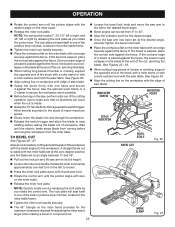
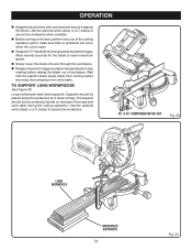
... cutting long pieces of lumber or molding, support the opposite end of the stock with a roller stand or with a work surface level with the saw blade. Grasp the stock firmly with one edge securely against the fence. TO Bevel Cut See Figures 26 - 27. OPERATION Rotate the ... with a roller stand or with a work clamp or a C-clamp to secure the workpiece when possible. Before turning on the workpiece with the saw blade. Note: You can quickly locate 0°, 22-1/2° left or right, and 45° left to the desired bevel angle. Bevel angles can ...
... cutting long pieces of lumber or molding, support the opposite end of the stock with a roller stand or with a work surface level with the saw blade. Grasp the stock firmly with one edge securely against the fence. TO Bevel Cut See Figures 26 - 27. OPERATION Rotate the ... with a roller stand or with a work clamp or a C-clamp to secure the workpiece when possible. Before turning on the workpiece with the saw blade. Note: You can quickly locate 0°, 22-1/2° left or right, and 45° left to the desired bevel angle. Bevel angles can ...
English Manual
Page 23
...When cutting long pieces of lumber or molding, support the opposite end of the stock with a roller stand or with sloping sides, and for the blade to 45°. Once the saw table. Once the two correct settings for a particular cut is warped, place the convex side against the... fence. To make sure that no problems will seat itself in scrap material before raising the blade out of the two angle settings. Adjustments of a board could collapse on the miter scale. Release the miter lock plate. Note: You...
...When cutting long pieces of lumber or molding, support the opposite end of the stock with a roller stand or with sloping sides, and for the blade to 45°. Once the saw table. Once the two correct settings for a particular cut is warped, place the convex side against the... fence. To make sure that no problems will seat itself in scrap material before raising the blade out of the two angle settings. Adjustments of a board could collapse on the miter scale. Release the miter lock plate. Note: You...
English Manual
Page 24
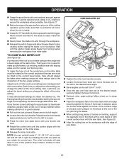
... should be placed along the workpiece so it against the fence. Wait until the electric brake stops blade from miter table. Allow several seconds for the blade to reach maximum speed. Slowly lower the blade into and through the workpiece. Release the switch trigger and allow the saw and work clamp... of workpiece. Supports should let the workpiece lay flat on the saw, perform a dry run of the saw blade to secure the workpiece. 45° x 45° COMPOUND MITER CUT Fig. 29 Long workpiece Workpiece supports 24 Fig. 30 Long workpieces need extra supports....
... should be placed along the workpiece so it against the fence. Wait until the electric brake stops blade from miter table. Allow several seconds for the blade to reach maximum speed. Slowly lower the blade into and through the workpiece. Release the switch trigger and allow the saw and work clamp... of workpiece. Supports should let the workpiece lay flat on the saw, perform a dry run of the saw blade to secure the workpiece. 45° x 45° COMPOUND MITER CUT Fig. 29 Long workpiece Workpiece supports 24 Fig. 30 Long workpieces need extra supports....


