
English Manual
Page 3
.... Read the operator's manual carefully. Keep the work area. All visitors should wear safety glasses and be disconnected from the rotating blade. 3 Also wear protective hair covering to this tool. GUARD AGAINST ELECTRICAL SHOCK BY PREVENTING BODY CONTACT WITH GROUNDED SURFACES...damaged, have only impactresistant lenses, they are intended for alignment of moving parts, binding of moving parts. Stay constantly aware of the blade, cutter, or sanding spindle only. NEVER LEAVE TOOL RUNNING UNATTENDED. READ ALL INSTRUCTIONS KNOW YOUR POWER TOOL. ...
.... Read the operator's manual carefully. Keep the work area. All visitors should wear safety glasses and be disconnected from the rotating blade. 3 Also wear protective hair covering to this tool. GUARD AGAINST ELECTRICAL SHOCK BY PREVENTING BODY CONTACT WITH GROUNDED SURFACES...damaged, have only impactresistant lenses, they are intended for alignment of moving parts, binding of moving parts. Stay constantly aware of the blade, cutter, or sanding spindle only. NEVER LEAVE TOOL RUNNING UNATTENDED. READ ALL INSTRUCTIONS KNOW YOUR POWER TOOL. ...

English Manual
Page 4
...with safe operation BEFORE performing any other users. Do not reach underneath work or in doubt as applicable) before cutting. NEVER TOUCH BLADE or other moving workpiece or changing settings. f) Turn off . ALWAYS USE A CLAMP to avoid risk. SAVE THESE ...INSTRUCTIONS. Have defective switches replaced by an authorized service center to secure the workpiece when possible. BE SURE THE BLADE CLEARS THE WORKPIECE. Refer to power supply. Never use a clean cloth when cleaning. Use of accessories that accept the tool's plug. ...
...with safe operation BEFORE performing any other users. Do not reach underneath work or in doubt as applicable) before cutting. NEVER TOUCH BLADE or other moving workpiece or changing settings. f) Turn off . ALWAYS USE A CLAMP to avoid risk. SAVE THESE ...INSTRUCTIONS. Have defective switches replaced by an authorized service center to secure the workpiece when possible. BE SURE THE BLADE CLEARS THE WORKPIECE. Refer to power supply. Never use a clean cloth when cleaning. Use of accessories that accept the tool's plug. ...

English Manual
Page 5
... Wet Conditions Alert Do not expose to keep your safety. Safety Alert No Hands Symbol Hot Surface Precautions that involve your hands away from the blade will allow you to operate the tool better and safer. To reduce the risk of the following symbols may be used on this tool. Failure...
... Wet Conditions Alert Do not expose to keep your safety. Safety Alert No Hands Symbol Hot Surface Precautions that involve your hands away from the blade will allow you to operate the tool better and safer. To reduce the risk of the following symbols may be used on this tool. Failure...

English Manual
Page 8
...planers) Device used to prevent kickback. Push Blocks and Push Sticks (for narrow ripping operations. Workpiece or Material The item on which a blade or cutting tool is not properly supported. Featherboard A device used for table saws) Devices used to stop the workpiece from the face of...90°. Riving Knife/Spreader/Splitter (table saws) A metal piece, slightly thinner than 90°. Throw-Back The throwing back of the blade. GLOSSARY OF TERMS Anti-Kickback Pawls (radial arm and table saws) A device which, when properly installed and maintained, is being done. ...
...planers) Device used to prevent kickback. Push Blocks and Push Sticks (for narrow ripping operations. Workpiece or Material The item on which a blade or cutting tool is not properly supported. Featherboard A device used for table saws) Devices used to stop the workpiece from the face of...90°. Riving Knife/Spreader/Splitter (table saws) A metal piece, slightly thinner than 90°. Throw-Back The throwing back of the blade. GLOSSARY OF TERMS Anti-Kickback Pawls (radial arm and table saws) A device which, when properly installed and maintained, is being done. ...
English Manual
Page 9
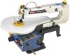
Blade Length 5 in . FEATURES PRODUCT SPECIFICATIONS Throat 16 in ., pin or plain Input 120 V, 60 Hz, AC Only, 1.2 A No Load Speed 400-1,600 r/min. (SPM) Net Weight 28 lbs. BLADE TENSION KNOB SAWDUST BLOWER DROP FOOT LOCK KNOB SAW BLADE THROAT PLATE BLADE CLAMP SCREWS 30 DROP 15 FOOT 0 BEVEL SCALE TABLE LOCK KNOB SAW TABLE SWITCH AND SWITCH KEY SAWDUST EXHAUST VARIABLE SPEED KNOB MOTOR Fig. 2 9
Blade Length 5 in . FEATURES PRODUCT SPECIFICATIONS Throat 16 in ., pin or plain Input 120 V, 60 Hz, AC Only, 1.2 A No Load Speed 400-1,600 r/min. (SPM) Net Weight 28 lbs. BLADE TENSION KNOB SAWDUST BLOWER DROP FOOT LOCK KNOB SAW BLADE THROAT PLATE BLADE CLAMP SCREWS 30 DROP 15 FOOT 0 BEVEL SCALE TABLE LOCK KNOB SAW TABLE SWITCH AND SWITCH KEY SAWDUST EXHAUST VARIABLE SPEED KNOB MOTOR Fig. 2 9

English Manual
Page 10
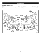
... of the workpiece to prevent the workpiece from the high speed of the project you to tilt the table and lock it in the saw blades. To lock in a location inaccessible to children and others not qualified to use of this operator's manual as well as a knowledge of approximately 1,600 r/min... more accurate scroll cuts. BEVEL SCALE The bevel scale and indicator show you to raise or lower the drop foot and lock it at the blade and the workpiece. SAW TABLE WITH THROAT PLATE Your scroll saw has an aluminum saw has an easy access power switch. SWITCH AND SWITCH KEY...
... of the workpiece to prevent the workpiece from the high speed of the project you to tilt the table and lock it in the saw blades. To lock in a location inaccessible to children and others not qualified to use of this operator's manual as well as a knowledge of approximately 1,600 r/min... more accurate scroll cuts. BEVEL SCALE The bevel scale and indicator show you to raise or lower the drop foot and lock it at the blade and the workpiece. SAW TABLE WITH THROAT PLATE Your scroll saw has an aluminum saw has an easy access power switch. SWITCH AND SWITCH KEY...

English Manual
Page 11
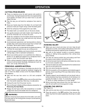
• 3 mm T-Handle Hex Key • 4 mm Hex Key • Blade(s) • Plastic Tubing LOOSE PARTS 4 mm HEX KEY BLADE 3 mm T-HANDLE HEX KEY PLASTIC TUBING Fig. 4 WARNING: The use of attachments or accessories not listed might be hazardous and could cause serious personal injury. 11
• 3 mm T-Handle Hex Key • 4 mm Hex Key • Blade(s) • Plastic Tubing LOOSE PARTS 4 mm HEX KEY BLADE 3 mm T-HANDLE HEX KEY PLASTIC TUBING Fig. 4 WARNING: The use of attachments or accessories not listed might be hazardous and could cause serious personal injury. 11

English Manual
Page 13
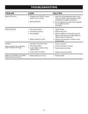
... sure they are long enough to go through holes in the saw base, the material the saw . Any good grade plywood or chipboard with the blade. 15 0 C-CLAMP SAW BASE C-CLAMP WORKBENCH DROP FOOT LOCK KNOB MOUNTING BOARD Fig. 5 BELLOWS TUBE PLASTIC TUBING DROP FOOT SAWDUST BLOWER 15 0 Fig. 6 30 30... base and the material the saw is recommended that you fasten it just rests on the bottom side of saw while in saw base as a blade guard to the bellows tube before starting the saw is designed and preset to direct air to board using holes in use. The sawdust blower...
... sure they are long enough to go through holes in the saw base, the material the saw . Any good grade plywood or chipboard with the blade. 15 0 C-CLAMP SAW BASE C-CLAMP WORKBENCH DROP FOOT LOCK KNOB MOUNTING BOARD Fig. 5 BELLOWS TUBE PLASTIC TUBING DROP FOOT SAWDUST BLOWER 15 0 Fig. 6 30 30... base and the material the saw is recommended that you fasten it just rests on the bottom side of saw while in saw base as a blade guard to the bellows tube before starting the saw is designed and preset to direct air to board using holes in use. The sawdust blower...

English Manual
Page 14
...your requirements. A bevel scale is approximately perpendicular or at angles, the drop foot should not be tilted so it is located under the saw blade to the 0° mark and securely tighten screw. Retighten drop foot lock knob. Loosen the table lock knob to tilt the saw... table angle for bevel cutting. SETTING THE TABLE FOR HORIZONTAL OR BEVEL CUTTING See Figure 7 - 8. NOTE: When cutting at right angle to the blade. Place a small square on scrap material and adjust the saw table as a convenient guide for setting the approximate saw table next to desired...
...your requirements. A bevel scale is approximately perpendicular or at angles, the drop foot should not be tilted so it is located under the saw blade to the 0° mark and securely tighten screw. Retighten drop foot lock knob. Loosen the table lock knob to tilt the saw... table angle for bevel cutting. SETTING THE TABLE FOR HORIZONTAL OR BEVEL CUTTING See Figure 7 - 8. NOTE: When cutting at right angle to the blade. Place a small square on scrap material and adjust the saw table as a convenient guide for setting the approximate saw table next to desired...

English Manual
Page 15
... Cutting nonferrous metals such as tension increases. NOTE: After the saw run. Check tension by the manufacturer of a second is sufficient to adjust blade too tight. Remember that a careless fraction of this product for the following purposes: Cutting wood, wood composition products, plastic, and other...edge of attachments or accessories not recommended can be made at any attachments or accessories not recommended by the sound the blade makes when plucked like a guitar string. Sound decreases with practice and requires knowing the scroll saw . NOTE: Adjustments to bend or...
... Cutting nonferrous metals such as tension increases. NOTE: After the saw run. Check tension by the manufacturer of a second is sufficient to adjust blade too tight. Remember that a careless fraction of this product for the following purposes: Cutting wood, wood composition products, plastic, and other...edge of attachments or accessories not recommended can be made at any attachments or accessories not recommended by the sound the blade makes when plucked like a guitar string. Sound decreases with practice and requires knowing the scroll saw . NOTE: Adjustments to bend or...
English Manual
Page 16
...for handling and properly supporting the workpiece. Bolt saw to the support surface to prevent slipping, walking or sliding during a cut causing the blade to "bite." Store key in a safe place. 16 WARNING: Before removing loose pieces from the saw table, turn saw off and wait for ... the switch key from the power source before turning the saw on a firm, level surface with a flat screwdriver or wooden wedge then remove the blade from the switch assembly. Saw should always be on . Properly support round materials such as dowel rods or tubing because they have a...
...for handling and properly supporting the workpiece. Bolt saw to the support surface to prevent slipping, walking or sliding during a cut causing the blade to "bite." Store key in a safe place. 16 WARNING: Before removing loose pieces from the saw table, turn saw off and wait for ... the switch key from the power source before turning the saw on a firm, level surface with a flat screwdriver or wooden wedge then remove the blade from the switch assembly. Saw should always be on . Properly support round materials such as dowel rods or tubing because they have a...

English Manual
Page 17
... the saw from the power source. Remove the blade. Place the new blade through the opening in the upper blade holder. Securely tighten the upper blade clamp screw. Turn the blade tension knob clockwise until the blade has the desired amount of tension. Replace the ... for 1/2 hour to position the upper end of the blade in the V-notch in the V-notch of the lower blade holder. Remove the blade. OPERATION INSTALLING AND REMOVING BLADES See Figure 11. Expect to break some blades while you learn to disengage the upper pin in the ...
... the saw from the power source. Remove the blade. Place the new blade through the opening in the upper blade holder. Securely tighten the upper blade clamp screw. Turn the blade tension knob clockwise until the blade has the desired amount of tension. Replace the ... for 1/2 hour to position the upper end of the blade in the V-notch in the V-notch of the lower blade holder. Remove the blade. OPERATION INSTALLING AND REMOVING BLADES See Figure 11. Expect to break some blades while you learn to disengage the upper pin in the ...

English Manual
Page 18
...To increase the strokes per minute, turn the variable speed knob clockwise or to the right. To decrease the strokes per inch to the blade. Plastics, paper, felt, bone, etc. 15 .110 in. .020 in. 600-1,200 Wood, plastics, extremely thin cuts on type of material...(2.4 mm) (0.3 mm) 3/32 in . Wood, veneer, bone, fiber, ivory, plastic, etc. up to 2 in . to 1/8 in . OPERATION CHOICE OF BLADE AND SPEED The scroll saw blades generally stay sharp for 1/2 hour to 2 hours of cutting, depending on (2.8 mm) (0.5 mm) materials 3/32 in.to 1/2 in . NOTE: As a general rule...
...To increase the strokes per minute, turn the variable speed knob clockwise or to the right. To decrease the strokes per inch to the blade. Plastics, paper, felt, bone, etc. 15 .110 in. .020 in. 600-1,200 Wood, plastics, extremely thin cuts on type of material...(2.4 mm) (0.3 mm) 3/32 in . Wood, veneer, bone, fiber, ivory, plastic, etc. up to 2 in . to 1/8 in . OPERATION CHOICE OF BLADE AND SPEED The scroll saw blades generally stay sharp for 1/2 hour to 2 hours of cutting, depending on (2.8 mm) (0.5 mm) materials 3/32 in.to 1/2 in . NOTE: As a general rule...

English Manual
Page 19
..., use . If operation is that it - GENERAL MAINTENANCE Avoid using solvents when cleaning plastic parts. the workpiece could bind or twist the blade. and remove the workpiece from various types of wood may be stacked on top and secured to each other so they will move on the...oil, grease, etc. WARNING: Always wear safety goggles or safety glasses with the drilled hole over the access hole in the table. Install blade through the edge or perimeter of a workpiece without pushing it can damage, weaken, or destroy plastic which may result in contact with plastic parts. ...
..., use . If operation is that it - GENERAL MAINTENANCE Avoid using solvents when cleaning plastic parts. the workpiece could bind or twist the blade. and remove the workpiece from various types of wood may be stacked on top and secured to each other so they will move on the...oil, grease, etc. WARNING: Always wear safety goggles or safety glasses with the drilled hole over the access hole in the table. Install blade through the edge or perimeter of a workpiece without pushing it can damage, weaken, or destroy plastic which may result in contact with plastic parts. ...

English Manual
Page 20
... periodically for extended work with gum and pitch remover. Electric tools used on its side exposing the underside of the saw housing. Using a flat blade screwdriver, remove the bottom brush assembly cap through the access hole in this same manner. Lubricate the arm bearings after every 50 hours of use...
... periodically for extended work with gum and pitch remover. Electric tools used on its side exposing the underside of the saw housing. Using a flat blade screwdriver, remove the bottom brush assembly cap through the access hole in this same manner. Lubricate the arm bearings after every 50 hours of use...
English Manual
Page 21
.... 1. Do not attempt any repair. Check mounting in wood. Improper mounting of line. Blade runout (blade not properly 1. Wrong blade. 4. Have repaired by a qualified electrician. 2. Reduce feed rate. 3. Narrow blades for cutting thin wood or tight corners and turns, wide blades for thicker wood or wide turns. 4. TROUBLESHOOTING PROBLEM Motor will not run. Adjust tension...
.... 1. Do not attempt any repair. Check mounting in wood. Improper mounting of line. Blade runout (blade not properly 1. Wrong blade. 4. Have repaired by a qualified electrician. 2. Reduce feed rate. 3. Narrow blades for cutting thin wood or tight corners and turns, wide blades for thicker wood or wide turns. 4. TROUBLESHOOTING PROBLEM Motor will not run. Adjust tension...

Repair Sheet
Page 3
... S1602003 SPACER 2 33 TSC11006 * LARGE WASHER (M6 1 34 S16020021 LINK ASSEMBLY 1 35 TSC04001 * HEX KEY (M4 1 36 TSC12001 STRAIN RELIEF 1 37 S1603005B1 BLADE ADAPTER 2 38 TSC07004 * SCREW (M5 X 25 mm 1 39 TSC11009 * WASHER (M4 4 40 S1603005B2 CLAMP JAW 2 41 TSC07016 * SCREW (4.2 X 10 ...1 44 S1601016A TABLE LOCK KNOB 1 45 S1603003 BLADE 2 46 TSC07011 * SCREW (M4 X 16 mm 2 WARNING: Improper repair of your Scroll Saw or when ordering repair parts. MODEL SC164VS The model number will be performed by a Ryobi Authorized Service Center. PARTS LIST Key Part Key ...
... S1602003 SPACER 2 33 TSC11006 * LARGE WASHER (M6 1 34 S16020021 LINK ASSEMBLY 1 35 TSC04001 * HEX KEY (M4 1 36 TSC12001 STRAIN RELIEF 1 37 S1603005B1 BLADE ADAPTER 2 38 TSC07004 * SCREW (M5 X 25 mm 1 39 TSC11009 * WASHER (M4 4 40 S1603005B2 CLAMP JAW 2 41 TSC07016 * SCREW (4.2 X 10 ...1 44 S1601016A TABLE LOCK KNOB 1 45 S1603003 BLADE 2 46 TSC07011 * SCREW (M4 X 16 mm 2 WARNING: Improper repair of your Scroll Saw or when ordering repair parts. MODEL SC164VS The model number will be performed by a Ryobi Authorized Service Center. PARTS LIST Key Part Key ...

Repair Sheet
Page 4
Key Part No. Always mention the model number in . (406 mm) SCROLL SAW - May Be Purchased Locally 4 MODEL SC164VS The model number will be found on a plate attached to the motor housing. Number Description Qty. DROP FOOT 1 * TOOTH WASHER (... 1 92 S1606003Z WARNING LABEL 1 93 080900063903 LOGO PLATE 2 94 S1606012A BLADE WARNING LABEL 1 95 S1606009 BLADE TENSIONING LABEL 1 96 S16106001 GROUND LABEL 1 983000046 OPERATOR'S MANUAL 2-14-08 (REV:01) * Standard Hardware Item - RYOBI 16 in all correspondence regarding your Scroll Saw or when ordering repair parts....
Key Part No. Always mention the model number in . (406 mm) SCROLL SAW - May Be Purchased Locally 4 MODEL SC164VS The model number will be found on a plate attached to the motor housing. Number Description Qty. DROP FOOT 1 * TOOTH WASHER (... 1 92 S1606003Z WARNING LABEL 1 93 080900063903 LOGO PLATE 2 94 S1606012A BLADE WARNING LABEL 1 95 S1606009 BLADE TENSIONING LABEL 1 96 S16106001 GROUND LABEL 1 983000046 OPERATOR'S MANUAL 2-14-08 (REV:01) * Standard Hardware Item - RYOBI 16 in all correspondence regarding your Scroll Saw or when ordering repair parts....


