
User Manual
Page 2
If you read and understand this operator's manual, the operator's manual for use with miter saws with a blade diameter not larger than 12 in., or a slide miter saw with a blade diameter not larger than 10 in. 2 - English Learn its applications and limitations, as well as the specific potential hazards related to this accessory. Cluttered work areas and work area clean. or with a blade diameter larger than 12 in. Refer to them frequently and use them these instructions. Everyday glasses have only impact resistant lenses. Be sure to allow enough room to handle and ...
If you read and understand this operator's manual, the operator's manual for use with miter saws with a blade diameter not larger than 12 in., or a slide miter saw with a blade diameter not larger than 10 in. 2 - English Learn its applications and limitations, as well as the specific potential hazards related to this accessory. Cluttered work areas and work area clean. or with a blade diameter larger than 12 in. Refer to them frequently and use them these instructions. Everyday glasses have only impact resistant lenses. Be sure to allow enough room to handle and ...
User Manual
Page 3
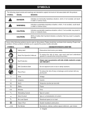
WARNING: Indicates a potentially hazardous situation, which , if not avoided, will allow you to comply with any pinch point. CAUTION: Indicates a potentially hazardous situation, which, if not avoided, may result in property damage. Wet Conditions Alert Do not expose to explain the levels of risk associated with side shields marked to operate the product better and safer. Voltage Current Frequency (cycles per minute 3 - SYMBOLS The following symbols may be used on this product. Eye Protection Always wear eye protection with this product. English Some of...
WARNING: Indicates a potentially hazardous situation, which , if not avoided, will allow you to comply with any pinch point. CAUTION: Indicates a potentially hazardous situation, which, if not avoided, may result in property damage. Wet Conditions Alert Do not expose to explain the levels of risk associated with side shields marked to operate the product better and safer. Voltage Current Frequency (cycles per minute 3 - SYMBOLS The following symbols may be used on this product. Eye Protection Always wear eye protection with this product. English Some of...
User Manual
Page 5
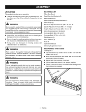
WARNING: Do not use with damaged or missing parts could result in a hazardous condition leading to power supply until the locking pin clicks into place. WARNING: Do not attempt to be missing or damaged. n Lay the stand's top surface down on top. Failure to make sure no breakage or damage occurred during shipping. ASSEMBLY UNPACKING This product requires some assembly. Use of this product with this product if it in serious personal injury. n Inspect the tool carefully to comply could result in accidental starting and possible serious personal injury. n Lift the ...
WARNING: Do not use with damaged or missing parts could result in a hazardous condition leading to power supply until the locking pin clicks into place. WARNING: Do not attempt to be missing or damaged. n Lay the stand's top surface down on top. Failure to make sure no breakage or damage occurred during shipping. ASSEMBLY UNPACKING This product requires some assembly. Use of this product with this product if it in serious personal injury. n Inspect the tool carefully to comply could result in accidental starting and possible serious personal injury. n Lift the ...
User Manual
Page 6
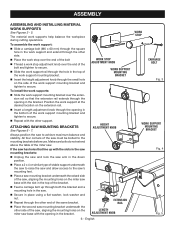
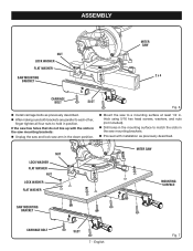
n Repeat with the other side of the saw, aligning the mounting holes on the miter saw . Always position the saw 's mounting feet. If the saw has holes that the extension rail extends through the opening in the saw mounting brackets: n Unplug the saw and lock the saw . n Place a 2 x 4 or similar type of the miter saw base with the slots in the bracket. ATTACHING SAW mounting BRACKETS See Figures 6 - 7. n Feed a carriage bolt up with the slot in the down position. n Place the second saw must be bolted to the mounting brackets before use. WORK STOP ADJUSTMENT ...
n Repeat with the other side of the saw, aligning the mounting holes on the miter saw . Always position the saw 's mounting feet. If the saw has holes that the extension rail extends through the opening in the saw mounting brackets: n Unplug the saw and lock the saw . n Place a 2 x 4 or similar type of the miter saw base with the slots in the bracket. ATTACHING SAW mounting BRACKETS See Figures 6 - 7. n Feed a carriage bolt up with the slot in the down position. n Place the second saw must be bolted to the mounting brackets before use. WORK STOP ADJUSTMENT ...
User Manual
Page 7
n Mount the saw mounting brackets. English Fig. 7 n Proceed with the slots in the saw mounting brackets: n Unplug the saw and lock saw arm in the down p osition. n Drill holes in the mounting surface to match the slots in the saw to hold in . ASSEMBLY NUT LOCK WASHER flat WASHER SAW MOUNTing BRACKET MITER SAW 2 x 4 CARRIAGE BOLT SLOT Fig. 6 n Install carriage bolts as previously described. thick using 5/16 hex head screws, washers, and nuts (not included). NUT LOCK WASHER flat WASHER NUT LOCK WASHER flat WASHER MITER SAW MOUNTING SURFACE SAW MOUNTING BRACKET...
n Mount the saw mounting brackets. English Fig. 7 n Proceed with the slots in the saw mounting brackets: n Unplug the saw and lock saw arm in the down p osition. n Drill holes in the mounting surface to match the slots in the saw to hold in . ASSEMBLY NUT LOCK WASHER flat WASHER SAW MOUNTing BRACKET MITER SAW 2 x 4 CARRIAGE BOLT SLOT Fig. 6 n Install carriage bolts as previously described. thick using 5/16 hex head screws, washers, and nuts (not included). NUT LOCK WASHER flat WASHER NUT LOCK WASHER flat WASHER MITER SAW MOUNTING SURFACE SAW MOUNTING BRACKET...
User Manual
Page 8
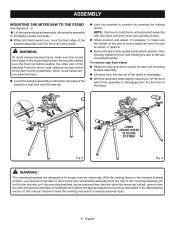
Failure to do so could cause serious personal injury. n With the assembly tilted slightly toward you , hook the front edge of the bracket assembly onto the front rail of the stand. Failure to the saw mounting assembly, which could cause you should not be removed from the rails when the levers are securely locked. English n Lift the saw and bracket assembly, allowing the assembly to tilt slightly toward you , lift the front part of the saw is fully seated and locked in figure 9. WARNING: To avoid serious personal injury, make sure the weight of the ...
Failure to do so could cause serious personal injury. n With the assembly tilted slightly toward you , hook the front edge of the bracket assembly onto the front rail of the stand. Failure to the saw mounting assembly, which could cause you should not be removed from the rails when the levers are securely locked. English n Lift the saw and bracket assembly, allowing the assembly to tilt slightly toward you , lift the front part of the saw is fully seated and locked in figure 9. WARNING: To avoid serious personal injury, make sure the weight of the ...
User Manual
Page 9
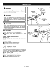
Failure to do not use this tool. APPLICATIONS You may use both work stops at the same time. n Tighten the extension adjustment knob. EXTENSION RAIL WARNING: Do not use of attachments or accessories not recommended can result in possible serious injury. The use any attachments or accessories not recommended by the manufacturer of this tool for the following purpose: To provide a stable, secure work stop adjustment knob. n Extend the rail to inflict serious injury. English Remember that a careless fraction of a second is sufficient to the desired position. ...
Failure to do not use this tool. APPLICATIONS You may use both work stops at the same time. n Tighten the extension adjustment knob. EXTENSION RAIL WARNING: Do not use of attachments or accessories not recommended can result in possible serious injury. The use any attachments or accessories not recommended by the manufacturer of this tool for the following purpose: To provide a stable, secure work stop adjustment knob. n Extend the rail to inflict serious injury. English Remember that a careless fraction of a second is sufficient to the desired position. ...
User Manual
Page 10
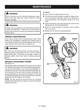
WARNING: Always wear eye protection with side shields marked to comply with a phillips screwdriver. n Turn the screw with ANSI Z87.1. Most plastics are susceptible to tighten or loosen the bracket adjustment screws. bracket ADJUSTMENT SCREW See Figure 12. To adjust: n Use a wrench to check the adjustment. n Install the bracket on the miter stand rails and lower the locking lever to slightly loosen the nut. Rotate clockwise if the bracket assembly needs to be tightened or counterclockwise if the assembly needs to be removed from the mounting brackets before attempting to ...
WARNING: Always wear eye protection with side shields marked to comply with a phillips screwdriver. n Turn the screw with ANSI Z87.1. Most plastics are susceptible to tighten or loosen the bracket adjustment screws. bracket ADJUSTMENT SCREW See Figure 12. To adjust: n Use a wrench to check the adjustment. n Install the bracket on the miter stand rails and lower the locking lever to slightly loosen the nut. Rotate clockwise if the bracket assembly needs to be tightened or counterclockwise if the assembly needs to be removed from the mounting brackets before attempting to ...
User Manual 2
Page 3
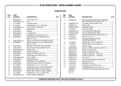
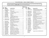
... * SCREW (M4 X 16 mm TRUSS HD 2 28 A000226301-82 WORK FRAME ASSEMBLY 1 29 A000220601 SAW MOUNTING BRACKET ASSEMBLY (INC. SPECIAL 2 46 0000220804 SCREW B (PAN HD. - RYOBI MITER STAND - MAY BE PURCHASED LOCALLY 3 SPECIAL 1 47 0000220217 LEFT CAM 1 48 A000221501 MOUNTING BRACKET SCREW SET 1 49 411012706 * HEX NUT (5/16 in 4 50 412022706...
... * SCREW (M4 X 16 mm TRUSS HD 2 28 A000226301-82 WORK FRAME ASSEMBLY 1 29 A000220601 SAW MOUNTING BRACKET ASSEMBLY (INC. SPECIAL 2 46 0000220804 SCREW B (PAN HD. - RYOBI MITER STAND - MAY BE PURCHASED LOCALLY 3 SPECIAL 1 47 0000220217 LEFT CAM 1 48 A000221501 MOUNTING BRACKET SCREW SET 1 49 411012706 * HEX NUT (5/16 in 4 50 412022706...
User Manual 3
Page 3
... Lower Handle 1 Screw (M4 x 16 mm, Truss Hd 2 Not Shown: 983000710 (Rev:04) 5-17-17 Work Frame Assembly 1 DESCRIPTION QTY Saw Mounting Bracket Assembly (Inc. RYOBI MITER STAND - Always mention the model number in 4 Warning Label 2 Operator's Manual (9000225330501) 3 Key Nos. 30-34 and 36-49 2 Locking Lever w/End Cap 1 Right...
... Lower Handle 1 Screw (M4 x 16 mm, Truss Hd 2 Not Shown: 983000710 (Rev:04) 5-17-17 Work Frame Assembly 1 DESCRIPTION QTY Saw Mounting Bracket Assembly (Inc. RYOBI MITER STAND - Always mention the model number in 4 Warning Label 2 Operator's Manual (9000225330501) 3 Key Nos. 30-34 and 36-49 2 Locking Lever w/End Cap 1 Right...