

Manual 1
Page 2
... part of electric shock. Avoid body contact with the power tool or these are provided for carrying, pulling or unplugging the power tool. Any power tool that may result in any adjustments, changing accessories, or storing power tools. If damaged, have the switch on invites accidents. Remove any adjusting key or wrench before turning the power tool on and off -position before making any way. Save all times. Use of a cord...
... part of electric shock. Avoid body contact with the power tool or these are provided for carrying, pulling or unplugging the power tool. Any power tool that may result in any adjustments, changing accessories, or storing power tools. If damaged, have the switch on invites accidents. Remove any adjusting key or wrench before turning the power tool on and off -position before making any way. Save all times. Use of a cord...

Manual 1
Page 3
... the safety of the tool, a guard or other conditions that it must be properly repaired or replaced by poorly maintained power tools. Keep cutting tools sharp and clean. Check for and remove all nails from those intended could give the operator an electric shock. Know your power tool serviced by a qualified repair person using only identical replacement parts. English Following this rule will reduce the risk of parts, mounting, and...
... the safety of the tool, a guard or other conditions that it must be properly repaired or replaced by poorly maintained power tools. Keep cutting tools sharp and clean. Check for and remove all nails from those intended could give the operator an electric shock. Know your power tool serviced by a qualified repair person using only identical replacement parts. English Following this rule will reduce the risk of parts, mounting, and...
Manual 1
Page 4
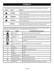
... no .../min Wet Conditions Alert Volts Amperes Hertz Watt Minutes Alternating Current No Load Speed Class II Construction Per Minute Do not expose to comply with ANSI Z87.1. V A Hz W min no load Double-insulated construction Revolutions, strokes, surface speed, orbits etc., per second) Power Time Type of injury, user must read and understand operator's manual before using this product. Voltage Current...
... no .../min Wet Conditions Alert Volts Amperes Hertz Watt Minutes Alternating Current No Load Speed Class II Construction Per Minute Do not expose to comply with ANSI Z87.1. V A Hz W min no load Double-insulated construction Revolutions, strokes, surface speed, orbits etc., per second) Power Time Type of injury, user must read and understand operator's manual before using this product. Voltage Current...
Manual 1
Page 5
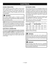
Always use . ELECTRICAL CONNECTION This tool has a precision-built electric motor. If your nearest authorized service center for the usual threewire grounded power cord. Use the chart to determine the minimum wire size required in serious personal injury. Failure to do not need for repair. WARNING: Check extension cords before each use original factory replacement parts when servicing. Observe all normal safety precautions to your tool does not operate when plugged into...
Always use . ELECTRICAL CONNECTION This tool has a precision-built electric motor. If your nearest authorized service center for the usual threewire grounded power cord. Use the chart to determine the minimum wire size required in serious personal injury. Failure to do not need for repair. WARNING: Check extension cords before each use original factory replacement parts when servicing. Observe all normal safety precautions to your tool does not operate when plugged into...
Manual 1
Page 6
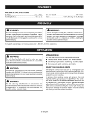
... edges Removing rust, paint, varnishes, and stains SELECTING SANDING BELTS Selecting the correct size and type of attachments or accessories not recommended can result in a hazardous condition leading to be sanded determines which grit will do so could result in serious personal injury. If the surface is rough, start with each grit until the surface is not completely assembled...
... edges Removing rust, paint, varnishes, and stains SELECTING SANDING BELTS Selecting the correct size and type of attachments or accessories not recommended can result in a hazardous condition leading to be sanded determines which grit will do so could result in serious personal injury. If the surface is rough, start with each grit until the surface is not completely assembled...
Manual 1
Page 7
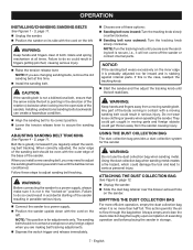
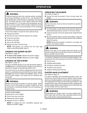
... air to adjust sanding belt tracking. OPERATION INSTALLING/CHANGING SANDING BELTS See Figures 1 - 3, page 11. Unplug the sander. Position the sander on its correct position. Lower the tension release lever to secure the sanding belt. When correctly adjusted, the outer edge of the sander. Follow these options: Sanding belt runs inward: Turn the tracking knob slowly counterclockwise. Sanding belt runs outward: Turn the tracking knob slowly clockwise. USING THE DUST COLLECTION BAG The dust...
... air to adjust sanding belt tracking. OPERATION INSTALLING/CHANGING SANDING BELTS See Figures 1 - 3, page 11. Unplug the sander. Position the sander on its correct position. Lower the tension release lever to secure the sanding belt. When correctly adjusted, the outer edge of the sander. Follow these options: Sanding belt runs inward: Turn the tracking knob slowly counterclockwise. Sanding belt runs outward: Turn the tracking knob slowly clockwise. USING THE DUST COLLECTION BAG The dust...
Manual 1
Page 8
... on feature engaged during use and the sander is accidentally disconnected from moving sanding belt, front idler roller, and drive roller assembly. When operating the sander, always hold the front handle with your left hand and the rear handle with both hands at all times. WARNING: Before connecting the sander to a power supply, make sure it is designed to lock the switch trigger in maintaining control, keeping...
... on feature engaged during use and the sander is accidentally disconnected from moving sanding belt, front idler roller, and drive roller assembly. When operating the sander, always hold the front handle with your left hand and the rear handle with both hands at all times. WARNING: Before connecting the sander to a power supply, make sure it is designed to lock the switch trigger in maintaining control, keeping...

Manual 1
Page 9
... right edge of the sander is not designed for contour sanding. Wash hands after handling. Sanding on the tool at the correct location. The front roller of the sander. serious personal injury could cause irregularity in the sanding belt tracking. When this type of these chemicals varies, depending on the drive roller and front roller. Use a coarser sanding belt for heavy sanding, not heavy pressure...
... right edge of the sander is not designed for contour sanding. Wash hands after handling. Sanding on the tool at the correct location. The front roller of the sander. serious personal injury could cause irregularity in the sanding belt tracking. When this type of these chemicals varies, depending on the drive roller and front roller. Use a coarser sanding belt for heavy sanding, not heavy pressure...
Manual 1
Page 10
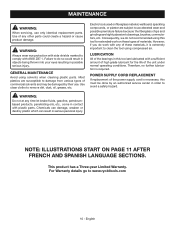
... possible serious injury. MAINTENANCE WARNING: When servicing, use . WARNING: Always wear eye protection with side shields marked to damage from various types of the unit under normal operating conditions. LUBRICATION All of materials. This product has a Three-year Limited Warranty. For Warranty details go to bearings, brushes, commutators, etc. POWER SUPPLY CORD REPLACEMENT If replacement of the power supply cord is necessary, this...
... possible serious injury. MAINTENANCE WARNING: When servicing, use . WARNING: Always wear eye protection with side shields marked to damage from various types of the unit under normal operating conditions. LUBRICATION All of materials. This product has a Three-year Limited Warranty. For Warranty details go to bearings, brushes, commutators, etc. POWER SUPPLY CORD REPLACEMENT If replacement of the power supply cord is necessary, this...

Manual 2
Page 2
RYOBI BELT SANDER - MODEL NUMBER BE319 35 36 8 3 4 1 9 2 12 10 32 13 11 14 15 34 33 32 38 37 35 39 5 6 16 7 17 18 19 20 21 22 24 23 26 25 13 31 12 30 28 30 29 27 52 51 49 50 40 41 42 43 44 46 45 47 48 Note: The assembly shown represents an important part of alteration or damage to the System, service should be performed by your nearest Ryobi authorized Service Center. To avoid the possibility of the double insulated system. For the service center nearest you call 1-800-525-2579. 2
RYOBI BELT SANDER - MODEL NUMBER BE319 35 36 8 3 4 1 9 2 12 10 32 13 11 14 15 34 33 32 38 37 35 39 5 6 16 7 17 18 19 20 21 22 24 23 26 25 13 31 12 30 28 30 29 27 52 51 49 50 40 41 42 43 44 46 45 47 48 Note: The assembly shown represents an important part of alteration or damage to the System, service should be performed by your nearest Ryobi authorized Service Center. To avoid the possibility of the double insulated system. For the service center nearest you call 1-800-525-2579. 2

Manual 2
Page 3
... Clamp 1 039820001002 Power Cord 1 039820001003 Bend Relief 1 039820001049 Hex Nut (M8 LH Threads 1 039820001105 Drum Wheel Assembly 1 039820001052 Washer 1 039820001053 Wave Washer 1 039820001054 Split Ring 1 039820001059 Adjustment Washer 1 039820001107 Drive Shaft Assembly 1 039820001055 Screw (M4.1 x 16 mm 4 039820001106 Support Assembly 1 039820001064 Dust Bag Assembly 1 039820001063 Sanding Belt 1 Not Shown: 991000168 Operator's Manual (961152363) 1-22-15 (Rev:01) WARNING: Improper repair of your BELT SANDER or when ordering repair parts. KEY...
... Clamp 1 039820001002 Power Cord 1 039820001003 Bend Relief 1 039820001049 Hex Nut (M8 LH Threads 1 039820001105 Drum Wheel Assembly 1 039820001052 Washer 1 039820001053 Wave Washer 1 039820001054 Split Ring 1 039820001059 Adjustment Washer 1 039820001107 Drive Shaft Assembly 1 039820001055 Screw (M4.1 x 16 mm 4 039820001106 Support Assembly 1 039820001064 Dust Bag Assembly 1 039820001063 Sanding Belt 1 Not Shown: 991000168 Operator's Manual (961152363) 1-22-15 (Rev:01) WARNING: Improper repair of your BELT SANDER or when ordering repair parts. KEY...

Manual 2
Page 4
MODEL NUMBER BE319 BRUSH ASSEMBLY BLACK MOTOR RED BLACK SWITCH BLACK RED WHITE POWER CORD WIRING DIAGRAM 4 BRUSH ASSEMBLY RYOBI BELT SANDER -
MODEL NUMBER BE319 BRUSH ASSEMBLY BLACK MOTOR RED BLACK SWITCH BLACK RED WHITE POWER CORD WIRING DIAGRAM 4 BRUSH ASSEMBLY RYOBI BELT SANDER -


