English Manual
Page 2
......2 Warranty...2 General Safety Rules...3-4 Specific Safety Rules...5 Symbols...6-7 Electrical...8 Glossary of Terms...9 Features...10-11 Tools Needed...11 Loose Parts...12 Assembly...13-17 Operation...18-20 Adjustments...21-22 Maintenance...23 Troubleshooting...24 Parts Ordering / Service...Back Page...
......2 Warranty...2 General Safety Rules...3-4 Specific Safety Rules...5 Symbols...6-7 Electrical...8 Glossary of Terms...9 Features...10-11 Tools Needed...11 Loose Parts...12 Assembly...13-17 Operation...18-20 Adjustments...21-22 Maintenance...23 Troubleshooting...24 Parts Ordering / Service...Back Page...
English Manual
Page 3
... 16 is tipped. CHECK DAMAGED PARTS. Failure to disconnect from tool before servicing, or when changing attachments, blades, bits, cutters, etc., all instructions listed below, may result in doubt, use , before turning it on the tool while it to follow all tools should be properly repaired or replaced by an authorized service center to this tool. GUARD AGAINST ELECTRICAL SHOCK BY PREVENTING BODY CONTACT WITH GROUNDED...
... 16 is tipped. CHECK DAMAGED PARTS. Failure to disconnect from tool before servicing, or when changing attachments, blades, bits, cutters, etc., all instructions listed below, may result in doubt, use , before turning it on the tool while it to follow all tools should be properly repaired or replaced by an authorized service center to this tool. GUARD AGAINST ELECTRICAL SHOCK BY PREVENTING BODY CONTACT WITH GROUNDED...
English Manual
Page 4
... FREE FROM OIL AND GREASE. Do not rush. DO NOT USE TOOL IF SWITCH DOES NOT TURN IT ON AND OFF. Instructions for safe use common sense. Repair or replace a damaged or worn cord immediately. If damaged, have repaired by an authorized service center. ALWAYS TURN SWITCH OFF before disconnecting it should be plugged into a three-hole electrical receptacle. Use only correct electrical devices: 3-wire extension cords...
... FREE FROM OIL AND GREASE. Do not rush. DO NOT USE TOOL IF SWITCH DOES NOT TURN IT ON AND OFF. Instructions for safe use common sense. Repair or replace a damaged or worn cord immediately. If damaged, have repaired by an authorized service center. ALWAYS TURN SWITCH OFF before disconnecting it should be plugged into a three-hole electrical receptacle. Use only correct electrical devices: 3-wire extension cords...
English Manual
Page 5
... approved safety equipment, such as those dust masks that the head and table support lock handle is aimed at a surface with respect to instruct other masonry products, and • arsenic and chromium from the bit. Your risk from the chuck before leaving machine. AVOID direct eye exposure when using the laser guide. Always ensure the laser beam is clamped tight to power source or turning power...
... approved safety equipment, such as those dust masks that the head and table support lock handle is aimed at a surface with respect to instruct other masonry products, and • arsenic and chromium from the bit. Your risk from the chuck before leaving machine. AVOID direct eye exposure when using the laser guide. Always ensure the laser beam is clamped tight to power source or turning power...
English Manual
Page 7
... Wide Vision Safety Mask for continuing safe operation and instructing others who may result in minor or moderate injury. (Without Safety Alert Symbol) Indicates a situation that may use over eyeglasses or standard safety glasses with ANSI Z87.1. WARNING: To avoid serious personal injury, do not attempt to use only identical replacement parts. Save this operator's manual and review frequently for use this product...
... Wide Vision Safety Mask for continuing safe operation and instructing others who may result in minor or moderate injury. (Without Safety Alert Symbol) Indicates a situation that may use over eyeglasses or standard safety glasses with ANSI Z87.1. WARNING: To avoid serious personal injury, do not attempt to use only identical replacement parts. Save this operator's manual and review frequently for use this product...
English Manual
Page 8
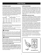
... extension cords before each use tool with all local codes and ordinances. Never use . Position the cord so that is equipped with a qualified electrician or service personnel if the grounding instructions are working area. Check with an electric cord having an outer surface that can result in doubt as the motor's horsepower rating. Electrical Extension Cords Use only 3-wire extension cords that have the proper outlet installed by...
... extension cords before each use tool with all local codes and ordinances. Never use . Position the cord so that is equipped with a qualified electrician or service personnel if the grounding instructions are working area. Check with an electric cord having an outer surface that can result in doubt as the motor's horsepower rating. Electrical Extension Cords Use only 3-wire extension cords that have the proper outlet installed by...
English Manual
Page 9
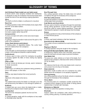
... Material The item on which a blade or cutting tool is not properly supported. Cutter Head (planers and jointers) A rotating piece of the workpiece. Ripping or Rip Cut A cutting operation along the length of adjustable blades. GLOSSARY OF TERMS Anti-Kickback Pawls (radial arm and table saws) A device which, when properly installed and maintained, is bent (or set) outward from the face of the blade. Dado Cut A non-through the thickness...
... Material The item on which a blade or cutting tool is not properly supported. Cutter Head (planers and jointers) A rotating piece of the workpiece. Ripping or Rip Cut A cutting operation along the length of adjustable blades. GLOSSARY OF TERMS Anti-Kickback Pawls (radial arm and table saws) A device which, when properly installed and maintained, is bent (or set) outward from the face of the blade. Dado Cut A non-through the thickness...
English Manual
Page 10
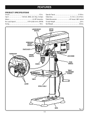
Input 120 Volt, 60Hz, AC Only, 3 Amps Motor 1/4 HP Induction No Load Speed 570-3,050 r/min. (RPM) Swing 10 in . laser on/off switch depth gauge worklight worklight on/off switch switch key power switch chuck table laser bevel scale lock knob feed handle table adjustment handle base 10 Fig. 2 Spindle Travel 2-3/8 in . Net Weight 62 lbs. FEATURES product specifications Chuck 1/2 in . Table Size 9-1/4 in . x 8-3/16 in . Table Movement 45° bevel, 360° swivel Overall Height 29 in .
Input 120 Volt, 60Hz, AC Only, 3 Amps Motor 1/4 HP Induction No Load Speed 570-3,050 r/min. (RPM) Swing 10 in . laser on/off switch depth gauge worklight worklight on/off switch switch key power switch chuck table laser bevel scale lock knob feed handle table adjustment handle base 10 Fig. 2 Spindle Travel 2-3/8 in . Net Weight 62 lbs. FEATURES product specifications Chuck 1/2 in . Table Size 9-1/4 in . x 8-3/16 in . Table Movement 45° bevel, 360° swivel Overall Height 29 in .
English Manual
Page 11
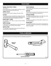
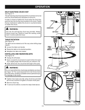
... motor for assembly and alignment: mallet or hammer adjustable wrench PHILLIPS SCREWDRIVER 11 Fig. 3 Chuck Your drill press features a standard three-jaw type chuck with a self-ejecting chuck key, which prevents accidentally starting the drill press with the key still engaged in drilling at desired depths. bevel scale The bevel scale indicates the degree the table is equipped with all operating features and safety rules. feed handles Feed handles raise and lower the chuck and bit...
... motor for assembly and alignment: mallet or hammer adjustable wrench PHILLIPS SCREWDRIVER 11 Fig. 3 Chuck Your drill press features a standard three-jaw type chuck with a self-ejecting chuck key, which prevents accidentally starting the drill press with the key still engaged in drilling at desired depths. bevel scale The bevel scale indicates the degree the table is equipped with all operating features and safety rules. feed handles Feed handles raise and lower the chuck and bit...
English Manual
Page 13
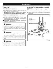
... when needed. Inspect the tool carefully to possible serious personal injury. WARNING: If any accessories from ...parts, and satisfactorily operated the tool. If any parts are replaced. attaching column assembly to power supply until assembly is complete. Note: This tool is misuse and could result in each hole and tighten using an adjust- Any such alteration or modification is heavy. able wrench. Align screw holes in the column assembly with this tool. ASSEMBLY UNPACKING This product requires assembly. Carefully remove the tool and any parts...
... when needed. Inspect the tool carefully to possible serious personal injury. WARNING: If any accessories from ...parts, and satisfactorily operated the tool. If any parts are replaced. attaching column assembly to power supply until assembly is complete. Note: This tool is misuse and could result in each hole and tighten using an adjust- Any such alteration or modification is heavy. able wrench. Align screw holes in the column assembly with this tool. ASSEMBLY UNPACKING This product requires assembly. Carefully remove the tool and any parts...

English Manual
Page 14
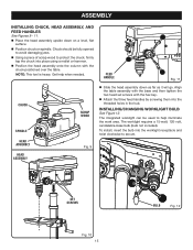
... the set screw. Insert it into the threaded hole at the rear of the table assembly and tighten by hand. The worm gear should be able to side. Locate the table lock handle. assembly installing table assembly See Figures 6 - 8. ■ Loosen the set screw in the collar using the hex key. Feed the gear rack through the hole in the table assembly. Install table adjustment handle over the column until the beveled side...
... the set screw. Insert it into the threaded hole at the rear of the table assembly and tighten by hand. The worm gear should be able to side. Locate the table lock handle. assembly installing table assembly See Figures 6 - 8. ■ Loosen the set screw in the collar using the hex key. Feed the gear rack through the hole in the table assembly. Install table adjustment handle over the column until the beveled side...
English Manual
Page 15
... when needed. Fig. 9 head assembly set screws with the chuck positioned over the table. The worklight requires a 15-watt, 120-volt, candelabra-base bulb (bulb not included). Note: This tool is heavy. Align the table assembly with the base and then tighten the two head set screws Fig. 10 15 bulb Fig. 12 Chuck should be used to protect the chuck, firmly tap the chuck into place using a mallet or hammer. ...
... when needed. Fig. 9 head assembly set screws with the chuck positioned over the table. The worklight requires a 15-watt, 120-volt, candelabra-base bulb (bulb not included). Note: This tool is heavy. Align the table assembly with the base and then tighten the two head set screws Fig. 10 15 bulb Fig. 12 Chuck should be used to protect the chuck, firmly tap the chuck into place using a mallet or hammer. ...

English Manual
Page 18
... the bit before operating the switch to start the tool. APPLICATIONS You may use of this warning may cause the workpiece to be kicked back toward the operator and result in a safe place. TO TURN THE DRILL PRESS OFF: With the switch key inserted into the switch, lift the switch to inflict serious injury. WARNING: Always remove the switch key when the tool is sufficient to turn the switch...
... the bit before operating the switch to start the tool. APPLICATIONS You may use of this warning may cause the workpiece to be kicked back toward the operator and result in a safe place. TO TURN THE DRILL PRESS OFF: With the switch key inserted into the switch, lift the switch to inflict serious injury. WARNING: Always remove the switch key when the tool is sufficient to turn the switch...
English Manual
Page 19
... larger than the bit size you intend to use a wrench to be rotated out of the jaws. In order to a point where the open- Do not use . Insert drill bit into the chuck the full length of the way when drilling large objects. Loosen the table lock handle. Rotate the table to the desired position. Retighten the table lock handle installing and removing bits See Figure...
... larger than the bit size you intend to use a wrench to be rotated out of the jaws. In order to a point where the open- Do not use . Insert drill bit into the chuck the full length of the way when drilling large objects. Loosen the table lock handle. Rotate the table to the desired position. Retighten the table lock handle installing and removing bits See Figure...
English Manual
Page 20
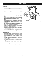
... drill bit based on the hole size desired. let the drill press do the work table is free of all loose objects and the bit is not in contact with oil to improve drilling action and increase bit life. As you increase the drill size, you may need to Adjusting Table Height in the Adjustments section of this manual. If desired, set the recommended spindle speed. Operation drilling See Figure 20. Using a clamping...
... drill bit based on the hole size desired. let the drill press do the work table is free of all loose objects and the bit is not in contact with oil to improve drilling action and increase bit life. As you increase the drill size, you may need to Adjusting Table Height in the Adjustments section of this manual. If desired, set the recommended spindle speed. Operation drilling See Figure 20. Using a clamping...
English Manual
Page 22
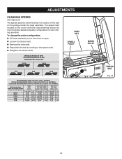
drive belt SPINDLE PULLEY MOTOR PULLEY TENSION bolt Fig. 24 22 adjustments CHANGING SPEEDS See Figure 24. To change the pulley configuration: Lift head assembly cover from front to open. Loosen the tension bolt. Remove the drive belt. Reposition the belt according to the speed chart. Retighten the tension bolt. The spindle speed is determined by the location of the belt on the cover...
drive belt SPINDLE PULLEY MOTOR PULLEY TENSION bolt Fig. 24 22 adjustments CHANGING SPEEDS See Figure 24. To change the pulley configuration: Lift head assembly cover from front to open. Loosen the tension bolt. Remove the drive belt. Reposition the belt according to the speed chart. Retighten the tension bolt. The spindle speed is determined by the location of the belt on the cover...
English Manual
Page 23
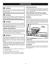
... side shields during power tool operation or when blowing dust. MOTOR/ELECTRICAL The induction motor is dusty, also wear a dust mask. MAINTENANCE WARNING: When servicing, use . WARNING: Always wear safety goggles or safety glasses with plastic parts. Use clean cloths to avoid deterioration. To make sure the pulleys are permanently lubricated and need no further attention. pulley set screw with the hex key. GENERAL MAINTENANCE Avoid using the laser for an extended...
... side shields during power tool operation or when blowing dust. MOTOR/ELECTRICAL The induction motor is dusty, also wear a dust mask. MAINTENANCE WARNING: When servicing, use . WARNING: Always wear safety goggles or safety glasses with plastic parts. Use clean cloths to avoid deterioration. To make sure the pulleys are permanently lubricated and need no further attention. pulley set screw with the hex key. GENERAL MAINTENANCE Avoid using the laser for an extended...
English Manual
Page 24
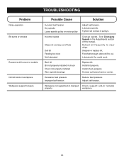
... pressure. Workpiece not supported or clamped Check support and/or reclamp properly workpiece. 24 Install chuck properly. Tighten set screws in chuck Chuck not properly installed Worn spindle bearings Replace bit. Bent bit Bit not properly installed in pulleys. Feed fast enough; Contact authorized service center. Incorrect speed Chips not coming out of this manual. Install bit properly. Lubricate spindle. Sharpen or replace bit. Retract bit frequently to cut. Adjust belt tension. troubleshooting Problem Noisy operation Bit burns or smokes Excessive drill...
... pressure. Workpiece not supported or clamped Check support and/or reclamp properly workpiece. 24 Install chuck properly. Tighten set screws in chuck Chuck not properly installed Worn spindle bearings Replace bit. Bent bit Bit not properly installed in pulleys. Feed fast enough; Contact authorized service center. Incorrect speed Chips not coming out of this manual. Install bit properly. Lubricate spindle. Sharpen or replace bit. Retract bit frequently to cut. Adjust belt tension. troubleshooting Problem Noisy operation Bit burns or smokes Excessive drill...
Repair Sheet
Page 3
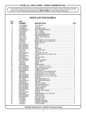
... BALL BEARING (60203 2 13302023A SPACER 1 089140200041 PULLEY INSERT 1 089140200042 RETAINING RING (22 1 089140200043 PULLEY SPINDLE 1 089140200044 LIGHT SWITCH 2 089140200045 SWITCH BOX 1 13202021 SPECIAL SET SCREW 1 089140200047 BAFFLE 1 TDP03002 * SCREW (M8 X 8 mm HEX HD 1 089140200049 HEAD STOCK 1 089140200050 BATTERY BOX 1 TDP06002 * HEX NUT (M10 2 13104008 SPRING CAP 1 13104009 TORSION SPRING 1 13104007 SPRING RETAINER 1 13202014 CORD CLAMP 4 * Standard Hardware Item - Always mention the model number in .
... BALL BEARING (60203 2 13302023A SPACER 1 089140200041 PULLEY INSERT 1 089140200042 RETAINING RING (22 1 089140200043 PULLEY SPINDLE 1 089140200044 LIGHT SWITCH 2 089140200045 SWITCH BOX 1 13202021 SPECIAL SET SCREW 1 089140200047 BAFFLE 1 TDP03002 * SCREW (M8 X 8 mm HEX HD 1 089140200049 HEAD STOCK 1 089140200050 BATTERY BOX 1 TDP06002 * HEX NUT (M10 2 13104008 SPRING CAP 1 13104009 TORSION SPRING 1 13104007 SPRING RETAINER 1 13202014 CORD CLAMP 4 * Standard Hardware Item - Always mention the model number in .

Repair Sheet
Page 4
... mention the model number in 1 089140200912 LASER LABEL 1 089140200094 CAPACITOR (DP102 MOTOR 1 089140200096 WASHER 5 983000641 OPERATOR'S MANUAL 06-06-08 (REV:05) * Standard Hardware Item - KEY NO. 105 1 13202016 POWER CORD 1 13205007 BELT (K31 1 089140200080 * HEX KEY (3 mm 1 TDP04001 * HEX KEY (4 mm 1 089140200082 * HEX KEY (5 mm 1 089140200083 KNOB 3 089140200084 ROD 3 089140200085 HUB 1 089140200086 KNOB DEPTH SCREW 1 089140200087 * SCREW (M4.2 X 13 mm COUNTERSUNK HD 2 089140200088 BULB SOCKET WITH NUT 1 089140200089 BULB...
... mention the model number in 1 089140200912 LASER LABEL 1 089140200094 CAPACITOR (DP102 MOTOR 1 089140200096 WASHER 5 983000641 OPERATOR'S MANUAL 06-06-08 (REV:05) * Standard Hardware Item - KEY NO. 105 1 13202016 POWER CORD 1 13205007 BELT (K31 1 089140200080 * HEX KEY (3 mm 1 TDP04001 * HEX KEY (4 mm 1 089140200082 * HEX KEY (5 mm 1 089140200083 KNOB 3 089140200084 ROD 3 089140200085 HUB 1 089140200086 KNOB DEPTH SCREW 1 089140200087 * SCREW (M4.2 X 13 mm COUNTERSUNK HD 2 089140200088 BULB SOCKET WITH NUT 1 089140200089 BULB...


