English Manual
Page 1
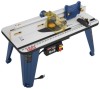
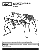
OPERATOR'S MANUAL ROUTER TABLE A25RT02 3 2 1 0 1 Inch inch 3 2 1 0 1 Inch Your router table has been engineered and manufactured to our high standard for your purchase. WARNING: To reduce the risk of operation, and operator safety. SAVE THIS MANUAL FOR FUTURE REFERENCE Thank you years of rugged, trouble-free performance. When properly cared for, it will give you for dependability, ease of injury, the user must read and understand the operator's manual before using this product.
OPERATOR'S MANUAL ROUTER TABLE A25RT02 3 2 1 0 1 Inch inch 3 2 1 0 1 Inch Your router table has been engineered and manufactured to our high standard for your purchase. WARNING: To reduce the risk of operation, and operator safety. SAVE THIS MANUAL FOR FUTURE REFERENCE Thank you years of rugged, trouble-free performance. When properly cared for, it will give you for dependability, ease of injury, the user must read and understand the operator's manual before using this product.
English Manual
Page 3
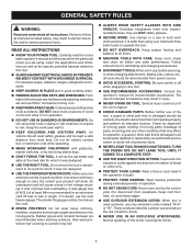
...to disconnect from work when practical, it is used outdoors, use power tools in injury. NEVER STAND ON TOOL. Carefully read the router table operator's manual and the manual for outdoor use and reduce the risk of improper accessories may result in damp or wet locations or expose to...DO NOT LEAVE TOOL UNTIL IT COMES TO A COMPLETE STOP. USE THE RIGHT DIRECTION OF FEED. These cords are rated for the particular router you into a blade or cutter against the direction of rotation of wood on . KEEP WORK AREA CLEAN. READ ALL INSTRUCTIONS KNOW...
...to disconnect from work when practical, it is used outdoors, use power tools in injury. NEVER STAND ON TOOL. Carefully read the router table operator's manual and the manual for outdoor use and reduce the risk of improper accessories may result in damp or wet locations or expose to...DO NOT LEAVE TOOL UNTIL IT COMES TO A COMPLETE STOP. USE THE RIGHT DIRECTION OF FEED. These cords are rated for the particular router you into a blade or cutter against the direction of rotation of wood on . KEEP WORK AREA CLEAN. READ ALL INSTRUCTIONS KNOW...
English Manual
Page 4
... power source. DO NOT USE AWKWARD HAND POSITIONS. FIRMLY CLAMP OR BOLT THE ROUTER TABLE TO A WORK SURFACE so that the router table surface is the equipment-grounding conductor. Instructions for safe use only identical replacement parts. Do not reach ...you loan someone this router table operator's manual and the router manual before operating the router or using the router table. ALWAYS USE THE ARTICULATING ROUTER CUTTER BIT GUARD. WHEN USING THE ROUTER ON THE ROUTER TABLE, the router must be plugged into the router table switch outlet. ...
... power source. DO NOT USE AWKWARD HAND POSITIONS. FIRMLY CLAMP OR BOLT THE ROUTER TABLE TO A WORK SURFACE so that the router table surface is the equipment-grounding conductor. Instructions for safe use only identical replacement parts. Do not reach ...you loan someone this router table operator's manual and the router manual before operating the router or using the router table. ALWAYS USE THE ARTICULATING ROUTER CUTTER BIT GUARD. WHEN USING THE ROUTER ON THE ROUTER TABLE, the router must be plugged into the router table switch outlet. ...
English Manual
Page 7
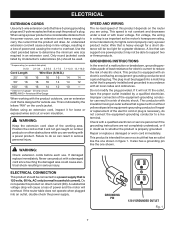
... check the power supply. It also has a grounding pin like the one shown in figure 1. Do not operate this product depends on the router you are working with a power product. A substantial voltage drop will overheat. Before using a power product at a considerable distance from the power...ELECTRICAL CONNECTION This product should be connected to a power supply that is properly installed and grounded in an extension cord. If the router table does not operate when plugged into a matching outlet that is as important as to determine the minimum wire size required in accordance ...
... check the power supply. It also has a grounding pin like the one shown in figure 1. Do not operate this product depends on the router you are working with a power product. A substantial voltage drop will overheat. Before using a power product at a considerable distance from the power...ELECTRICAL CONNECTION This product should be connected to a power supply that is properly installed and grounded in an extension cord. If the router table does not operate when plugged into a matching outlet that is as important as to determine the minimum wire size required in accordance ...
English Manual
Page 8
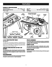
...has pre-drilled countersunk holes that can be used with all operating features and safety rules. 1 Inch FEDEIDRECTION FEATURES PRODUCT SPECIFICATIONS Table Dimensions 16 in . x 32 in . Before use of this product requires an understanding of the information on the fence assembly... 1 Inch FEATHER BOARD inch 3 2 1 0 1 Inch RESE T PUSH THROAT PLATES SWITCH ASSEMBLY RESET BUTTON MITER GAUGE Fig. 2 KNOW YOUR ROUTER TABLE See Figure 2. FEATHERBOARD The featherboard allows for mitered routing and to support and guide the work. x 32 in . FENCE ASSEMBLY The sacrifical MDF fence...
...has pre-drilled countersunk holes that can be used with all operating features and safety rules. 1 Inch FEDEIDRECTION FEATURES PRODUCT SPECIFICATIONS Table Dimensions 16 in . x 32 in . Before use of this product requires an understanding of the information on the fence assembly... 1 Inch FEATHER BOARD inch 3 2 1 0 1 Inch RESE T PUSH THROAT PLATES SWITCH ASSEMBLY RESET BUTTON MITER GAUGE Fig. 2 KNOW YOUR ROUTER TABLE See Figure 2. FEATHERBOARD The featherboard allows for mitered routing and to support and guide the work. x 32 in . FENCE ASSEMBLY The sacrifical MDF fence...
English Manual
Page 9
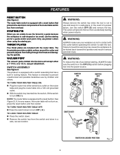
...outlet on , press the reset button and then restart. Failure to heed this warning may cause the workpiece to turn on the router table and plug the router table into a 120 volt grounded outlet. With the switch key inserted into the fence will prevent the tool from the switch...workpiece is not in a safe, secure location. SWITCH ASSEMBLY See Figure 3. WARNING: ALWAYS make sure the switch is in . TO LOCK YOUR ROUTER TABLE: Press the switch down to be kicked back toward the operator and result in locking feature. WARNING: Always remove the switch key when...
...outlet on , press the reset button and then restart. Failure to heed this warning may cause the workpiece to turn on the router table and plug the router table into a 120 volt grounded outlet. With the switch key inserted into the fence will prevent the tool from the switch...workpiece is not in a safe, secure location. SWITCH ASSEMBLY See Figure 3. WARNING: ALWAYS make sure the switch is in . TO LOCK YOUR ROUTER TABLE: Press the switch down to be kicked back toward the operator and result in locking feature. WARNING: Always remove the switch key when...

English Manual
Page 10
... 21. Miter Gauge 18. Featherboard Bolts (2) 22. Featherboard Lock Knobs (2) 24. Table Leg Phillips Head Screw (16) 4. Router Insert Plate Screws (5/16-18 x 3/4 in place before using the router table. WARNING: Do not attempt to possible serious personal injury. WARNING: The undertable guards must... be securely in .) (3) 14. Table Top 5. Switch Box Screw (3) 7. Any such alteration or modification ...
... 21. Miter Gauge 18. Featherboard Bolts (2) 22. Featherboard Lock Knobs (2) 24. Table Leg Phillips Head Screw (16) 4. Router Insert Plate Screws (5/16-18 x 3/4 in place before using the router table. WARNING: Do not attempt to possible serious personal injury. WARNING: The undertable guards must... be securely in .) (3) 14. Table Top 5. Switch Box Screw (3) 7. Any such alteration or modification ...
English Manual
Page 11
... plate. FRENCH / SPANISH LABEL LEFT LEG- Use these screws and nuts in the bag to attach the switch box. Place the router table upside down on a flat surface. Hold the switch box so that is the rail that the words ON and OFF on the ...the nuts on a flat surface. Position the under table guards in front of the under table guards. Place the router table upside down on the back of the table. NOTE: The table leg with the English language warning should go next to the router table. ENGLISH LABEL Fig. 7 11 The legs with a screwdriver...
... plate. FRENCH / SPANISH LABEL LEFT LEG- Use these screws and nuts in the bag to attach the switch box. Place the router table upside down on a flat surface. Hold the switch box so that is the rail that the words ON and OFF on the ...the nuts on a flat surface. Position the under table guards in front of the under table guards. Place the router table upside down on the back of the table. NOTE: The table leg with the English language warning should go next to the router table. ENGLISH LABEL Fig. 7 11 The legs with a screwdriver...
English Manual
Page 12
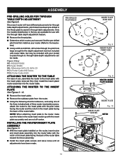
... With the insert plate installed on the router, insert router and insert plate assembly into the router table with the insert plate removed first, then install the insert plate/ router assembly into the router table. ASSEMBLY PRE-DRILLING HOLES FOR THROUGH TABLE DEPTH ADJUSTMENT See Figure 8. Only the models listed ...off-center. Figure 8 Key: RD: RIDGID R2930 RY: Ryobi R163K ML: Milwaukee 5615-20, 5616-20 PC1: Porter-Cable 890 Series PC2: Porter-Cable 8529 ATTACHING THE ROUTER TO THE TABLE For ease of the router table toward the fence assembly. Install the insert plate ...
... With the insert plate installed on the router, insert router and insert plate assembly into the router table with the insert plate removed first, then install the insert plate/ router assembly into the router table. ASSEMBLY PRE-DRILLING HOLES FOR THROUGH TABLE DEPTH ADJUSTMENT See Figure 8. Only the models listed ...off-center. Figure 8 Key: RD: RIDGID R2930 RY: Ryobi R163K ML: Milwaukee 5615-20, 5616-20 PC1: Porter-Cable 890 Series PC2: Porter-Cable 8529 ATTACHING THE ROUTER TO THE TABLE For ease of the router table toward the fence assembly. Install the insert plate ...
English Manual
Page 14
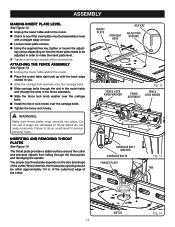
... in order to do not snap in serious personal injury. ASSEMBLY MAKING INSERT PLATE LEVEL See Figure 12. Unplug the router table and/or the router. Check to see if the insert plate mounted assembly is level with a screwdriver. ATTACHING THE FENCE ASSEMBLY See Figure ...13. Unplug the router table and/or the router. Place the router table right side up with the back edge closest to you. Slide the carriage bolt washers onto the carriage bolts...
... in order to do not snap in serious personal injury. ASSEMBLY MAKING INSERT PLATE LEVEL See Figure 12. Unplug the router table and/or the router. Check to see if the insert plate mounted assembly is level with a screwdriver. ATTACHING THE FENCE ASSEMBLY See Figure ...13. Unplug the router table and/or the router. Place the router table right side up with the back edge closest to you. Slide the carriage bolt washers onto the carriage bolts...

English Manual
Page 15
... to you are using the starting pin on the right. ATTACHING THE FEATHERBOARD See Figure 15. Unplug the router table and/or the router. Insert the featherboard bolts through the slots in the fence assembly. Slide the featherboard over the ... 1 0 DIFREEECDTION Inch 1 SLOT 15 Fig. 17 Place the starting pin. INSTALLING THE MITER GAUGE See Figure 17. Unplug the router table and/or the router. With the router table right side up, and the front edge closest to use. Press throat plate into place. 3 2 To remove, push...
... to you are using the starting pin on the right. ATTACHING THE FEATHERBOARD See Figure 15. Unplug the router table and/or the router. Insert the featherboard bolts through the slots in the fence assembly. Slide the featherboard over the ... 1 0 DIFREEECDTION Inch 1 SLOT 15 Fig. 17 Place the starting pin. INSTALLING THE MITER GAUGE See Figure 17. Unplug the router table and/or the router. With the router table right side up, and the front edge closest to use. Press throat plate into place. 3 2 To remove, push...

English Manual
Page 16
..., insert the top front of clamp through the work surface. Place the router table back on a sturdy work surface; ing the holes in the table legs with a pencil. Remove the router table. Drill four holes through the opening in the work surface, align- ... the holes in the router table leg. Tighten clamp securely. MOUNTING THE ROUTER TABLE TO A WORK BENCH See Figure 20. Unplug the router table and/or the router. Place the router table right side up on the work surface. NOTE: Position the router table surface at approximately hip ...
..., insert the top front of clamp through the work surface. Place the router table back on a sturdy work surface; ing the holes in the table legs with a pencil. Remove the router table. Drill four holes through the opening in the work surface, align- ... the holes in the router table leg. Tighten clamp securely. MOUNTING THE ROUTER TABLE TO A WORK BENCH See Figure 20. Unplug the router table and/or the router. Place the router table right side up on the work surface. NOTE: Position the router table surface at approximately hip ...
English Manual
Page 17
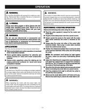
... safety glasses with the fence opening of this product. Failure to inflict serious injury. The "0" location on the table. Always plug the router into either of the router table switched outlets. WARNING: The router or router table should never be connected to a power supply when you are close to support the workpiece after the cut. NOTE...
... safety glasses with the fence opening of this product. Failure to inflict serious injury. The "0" location on the table. Always plug the router into either of the router table switched outlets. WARNING: The router or router table should never be connected to a power supply when you are close to support the workpiece after the cut. NOTE...
English Manual
Page 18
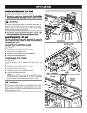
...desired angle. Tighten the miter gauge knob. ADJUSTING THE MITER GAUGE See Figure 21. Unplug the router table and/or the router. Loosen the miter gauge knob. Rotate the miter gauge to support the workpiece as it exits... DIFREEECDTION 3 2 3 1 2 0 1 Inch SCALE Fig. 22 18 OPERATION INSERTING/REMOVING CUTTERS Unplug the router table and/or the router. Remove the router/insert plate assembly. (See Installing Router/Insert Plate Assembly in the Assembly section.) WARNING: 3 2 1 0 1 Inch If you are changing a cutter immediately...
...desired angle. Tighten the miter gauge knob. ADJUSTING THE MITER GAUGE See Figure 21. Unplug the router table and/or the router. Loosen the miter gauge knob. Rotate the miter gauge to support the workpiece as it exits... DIFREEECDTION 3 2 3 1 2 0 1 Inch SCALE Fig. 22 18 OPERATION INSERTING/REMOVING CUTTERS Unplug the router table and/or the router. Remove the router/insert plate assembly. (See Installing Router/Insert Plate Assembly in the Assembly section.) WARNING: 3 2 1 0 1 Inch If you are changing a cutter immediately...

English Manual
Page 20
...drilling, and other construction activities contains chemicals known to these chemicals: work in a well ventilated area, and work . OPERATOR'S MANUAL ROUTER TABLE A25RT02 WARNING: Some dust created by calling 1-800-525-2579. To reduce your model and serial number from chemically-treated lumber. Some examples ..., • crystalline silica from bricks and cement and other reproductive harm. Replacement parts can also be obtained at one of Ryobi Limited used under license. Your risk from these chemicals are specially designed to filter out microscopic particles. • PARTS AND ...
...drilling, and other construction activities contains chemicals known to these chemicals: work in a well ventilated area, and work . OPERATOR'S MANUAL ROUTER TABLE A25RT02 WARNING: Some dust created by calling 1-800-525-2579. To reduce your model and serial number from chemically-treated lumber. Some examples ..., • crystalline silica from bricks and cement and other reproductive harm. Replacement parts can also be obtained at one of Ryobi Limited used under license. Your risk from these chemicals are specially designed to filter out microscopic particles. • PARTS AND ...
Repair Sheet
Page 2
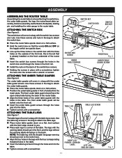
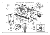
45 46 47 44 34 31 43 42 31 RYOBI ROUTER TABLE - MODEL NUMBER A25RT02 5 3 2 7 6 4 6 8 6 11 12 14 15 14 7 12 9 6 13 16 1 25 26 27 4 3 2 1 0 1 Inch 3 2 30 35 1 37 36 29 34 29 41 38 23 22 10 24 21 35 54 18 6 1 20 8 DIFREEECDTION 4 3 2 1 0 1 Inch 28 17 19 35 1 28 34 33 29 30 53 48 6 40 39 34 31 32 31 49 50 51 52 2
45 46 47 44 34 31 43 42 31 RYOBI ROUTER TABLE - MODEL NUMBER A25RT02 5 3 2 7 6 4 6 8 6 11 12 14 15 14 7 12 9 6 13 16 1 25 26 27 4 3 2 1 0 1 Inch 3 2 30 35 1 37 36 29 34 29 41 38 23 22 10 24 21 35 54 18 6 1 20 8 DIFREEECDTION 4 3 2 1 0 1 Inch 28 17 19 35 1 28 34 33 29 30 53 48 6 40 39 34 31 32 31 49 50 51 52 2
Repair Sheet
Page 3
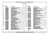
...20 9002800025 21 9002780055 22 9002800020 23 9002780034 24 9002780014 25 9002780009 9002780010 9002780011 9002780012 9002780013 26 9002780054 27 9002780072 RYOBI ROUTER TABLE - MODEL NUMBER A25RT02 PARTS LIST DESCRIPTION QTY * CARRIAGE BOLT (1/4-20 x 1 3/4 in 6 LEFT SLIDING FENCE FACE 1 JOINING ... (5/16-18 x 3/4 in 3 * SCREW (10-24 x 5/8 in 3 * SCREW (10-32 x 5/8 in 4 INSERT PLATE (INC. x 20 x 1/4 in 2 FEATHERBOARD 1 ROUTER TABLE TOP 1 * INSERT PLATE SCREW (10-24 x 3/4 in 2 T-TRACK NUT (10-24 8 * HEX BOLT (1/4-20 x 7/8 in 1 STARTING PIN 1 THROAT PLATE-A (1/2 in 1 ...
...20 9002800025 21 9002780055 22 9002800020 23 9002780034 24 9002780014 25 9002780009 9002780010 9002780011 9002780012 9002780013 26 9002780054 27 9002780072 RYOBI ROUTER TABLE - MODEL NUMBER A25RT02 PARTS LIST DESCRIPTION QTY * CARRIAGE BOLT (1/4-20 x 1 3/4 in 6 LEFT SLIDING FENCE FACE 1 JOINING ... (5/16-18 x 3/4 in 3 * SCREW (10-24 x 5/8 in 3 * SCREW (10-32 x 5/8 in 4 INSERT PLATE (INC. x 20 x 1/4 in 2 FEATHERBOARD 1 ROUTER TABLE TOP 1 * INSERT PLATE SCREW (10-24 x 3/4 in 2 T-TRACK NUT (10-24 8 * HEX BOLT (1/4-20 x 7/8 in 1 STARTING PIN 1 THROAT PLATE-A (1/2 in 1 ...


