English Manual
Page 1
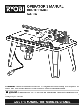
Thank you years of injury, the user must read and understand the operator's manual before using this product. OPERATOR'S MANUAL ROUTER TABLE A25RT02 3 2 1 0 1 Inch inch 3 2 1 0 1 Inch Your router table has been engineered and manufactured to our high standard for your purchase. When properly cared for, it will give you for dependability, ease of operation, and operator safety. SAVE THIS MANUAL FOR FUTURE REFERENCE WARNING: To reduce the risk of rugged, trouble-free performance.
Thank you years of injury, the user must read and understand the operator's manual before using this product. OPERATOR'S MANUAL ROUTER TABLE A25RT02 3 2 1 0 1 Inch inch 3 2 1 0 1 Inch Your router table has been engineered and manufactured to our high standard for your purchase. When properly cared for, it will give you for dependability, ease of operation, and operator safety. SAVE THIS MANUAL FOR FUTURE REFERENCE WARNING: To reduce the risk of rugged, trouble-free performance.
English Manual
Page 3
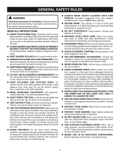
... "W-A" or "W". A guard or other conditions that can get caught and draw you are NOT safety glasses. SECURE WORK. Carefully read the router table operator's manual and the manual for which it to rain. Form habit of blade or cutter only. PROTECT YOUR LUNGS. Do not ... An undersized cord will do a job for better and safer performance. Keep proper footing and balance at the feed rate for the particular router you into a blade or cutter against the direction of rotation of checking to do the job better and safer at all instructions. GENERAL SAFETY...
... "W-A" or "W". A guard or other conditions that can get caught and draw you are NOT safety glasses. SECURE WORK. Carefully read the router table operator's manual and the manual for which it to rain. Form habit of blade or cutter only. PROTECT YOUR LUNGS. Do not ... An undersized cord will do a job for better and safer performance. Keep proper footing and balance at the feed rate for the particular router you into a blade or cutter against the direction of rotation of checking to do the job better and safer at all instructions. GENERAL SAFETY...

English Manual
Page 4
...the equipment-grounding conductor to clean tool. STAY ALERT AND EXERCISE CONTROL. The conductor with insulation having an outer surface that the router table surface is the equipment-grounding conductor. Following this tool. GENERAL SAFETY RULES INSPECT TOOL CORDS PERIODICALLY. If damaged, have ... by an authorized service center to a power source. DO NOT USE AWKWARD HAND POSITIONS. FIRMLY CLAMP OR BOLT THE ROUTER TABLE TO A WORK SURFACE so that is green with the accessory. If repair or replacement of any time while the tool is connected to...
...the equipment-grounding conductor to clean tool. STAY ALERT AND EXERCISE CONTROL. The conductor with insulation having an outer surface that the router table surface is the equipment-grounding conductor. Following this tool. GENERAL SAFETY RULES INSPECT TOOL CORDS PERIODICALLY. If damaged, have ... by an authorized service center to a power source. DO NOT USE AWKWARD HAND POSITIONS. FIRMLY CLAMP OR BOLT THE ROUTER TABLE TO A WORK SURFACE so that is green with the accessory. If repair or replacement of any time while the tool is connected to...
English Manual
Page 7
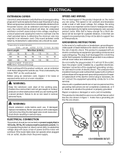
...conductor. ELECTRICAL CONNECTION This product should be connected to do not connect the equipment-grounding conductor to a live terminal. If the router table does not operate when plugged into a matching outlet that has an outlet like the one shown in an extension cord. WARNING...the minimum wire size required in figure 1. If damaged replace immediately. A line that can result in a loss of this product on the router you are working area. When using . GROUNDING INSTRUCTIONS In the event of a malfunction or breakdown, grounding provides a path of least resistance...
...conductor. ELECTRICAL CONNECTION This product should be connected to do not connect the equipment-grounding conductor to a live terminal. If the router table does not operate when plugged into a matching outlet that has an outlet like the one shown in an extension cord. WARNING...the minimum wire size required in figure 1. If damaged replace immediately. A line that can result in a loss of this product on the router you are working area. When using . GROUNDING INSTRUCTIONS In the event of a malfunction or breakdown, grounding provides a path of least resistance...
English Manual
Page 8
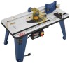
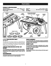
...assembly provides a barrier to protect the operator from contact with the cutter and is designed to stay in this product requires an understanding of routers. Rating 120 V, 60 Hz, AC only, 15 Amps Net Weight 28 lbs. FENCE ASSEMBLY The sacrifical MDF fence assembly provides an ...of this operator's manual as well as a knowledge of the workpiece through the cutter area and is the vacuum port. ARTICULATING ROUTER CUTTER / BIT GUARD The articulating router cutter bit guard on the product and in contact with all operating features and safety rules. Maximum Cutter Diameter 1-15/16 ...
...assembly provides a barrier to protect the operator from contact with the cutter and is designed to stay in this product requires an understanding of routers. Rating 120 V, 60 Hz, AC only, 15 Amps Net Weight 28 lbs. FENCE ASSEMBLY The sacrifical MDF fence assembly provides an ...of this operator's manual as well as a knowledge of the workpiece through the cutter area and is the vacuum port. ARTICULATING ROUTER CUTTER / BIT GUARD The articulating router cutter bit guard on the product and in contact with all operating features and safety rules. Maximum Cutter Diameter 1-15/16 ...
English Manual
Page 9
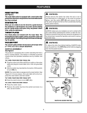
...THROAT PLATES Five throat plates are unable to start the tool. VACUUM PORT The vacuum ports molded into the power source. TO LOCK YOUR ROUTER TABLE: Press the switch down to prevent unauthorized and possible hazardous use piloted cutters when using the starting pin for a guide ...because the workpiece is equipped with the router table. The router table switch is odd-shaped or too small, use and keep it in a safe, secure location. This feature is intended to...
...THROAT PLATES Five throat plates are unable to start the tool. VACUUM PORT The vacuum ports molded into the power source. TO LOCK YOUR ROUTER TABLE: Press the switch down to prevent unauthorized and possible hazardous use piloted cutters when using the starting pin for a guide ...because the workpiece is equipped with the router table. The router table switch is odd-shaped or too small, use and keep it in a safe, secure location. This feature is intended to...

English Manual
Page 10
... 7. Under Table Guard (2) 18 DIFREEECDTION 23 19 22 3 20 3 2 1 0 1 Inch 17 21 16 15 14 13 12 11 Fig. 4 12. Router Insert Plate Screws (10-32 x 5/8 in .) (3) 15. Operator's Manual (not shown) 10 ASSEMBLY UNPACKING This product requires assembly. Carefully remove the ...(2) 23. WARNING: Do not connect to modify this product or create accessories not recommended for assistance. Table Leg (4) 2. Carriage Bolt Washer (2) 9. Router Insert Plate Screws (10-24 x 5/8 in .) (3) 16. WARNING: Do not attempt to power supply until the parts are replaced. Failure to ...
... 7. Under Table Guard (2) 18 DIFREEECDTION 23 19 22 3 20 3 2 1 0 1 Inch 17 21 16 15 14 13 12 11 Fig. 4 12. Router Insert Plate Screws (10-32 x 5/8 in .) (3) 15. Operator's Manual (not shown) 10 ASSEMBLY UNPACKING This product requires assembly. Carefully remove the ...(2) 23. WARNING: Do not connect to modify this product or create accessories not recommended for assistance. Table Leg (4) 2. Carriage Bolt Washer (2) 9. Router Insert Plate Screws (10-24 x 5/8 in .) (3) 16. WARNING: Do not attempt to power supply until the parts are replaced. Failure to ...
English Manual
Page 11
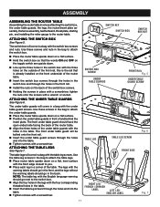
...words ON and OFF on the toggle switch are upside down on a flat surface. Position the under table guards, the legs, the router/insert plate assembly, the fence assembly, featherboard, throat plate, starting pin, and installing the miter gauge to the switch box. Align ...the table leg screws through the holes and into the table. Tighten screws with a wrench or socket. ASSEMBLY ASSEMBLING THE ROUTER TABLE Assembling the router table involves attaching the switch box, the under table guards in front of and behind the insert plate. ATTACHING THE UNDER TABLE GUARDS ...
...words ON and OFF on the toggle switch are upside down on a flat surface. Position the under table guards, the legs, the router/insert plate assembly, the fence assembly, featherboard, throat plate, starting pin, and installing the miter gauge to the switch box. Align ...the table leg screws through the holes and into the table. Tighten screws with a wrench or socket. ASSEMBLY ASSEMBLING THE ROUTER TABLE Assembling the router table involves attaching the switch box, the under table guards in front of and behind the insert plate. ATTACHING THE UNDER TABLE GUARDS ...
English Manual
Page 12
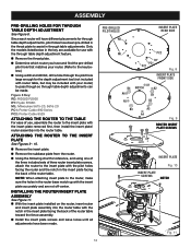
... SIDE B4 A6 A5 A1 NOTCH A2 B1 B2 B3 A3 A4 Fig. 9 ROUTER INSERT PLATE SCREWS 3 2 1 0 1 Inch INSERT PLATE Fig. 10 INSERT PLATE SCREWS NOTCH DIFREEECDTION 3 2 1 0 1 Fig. Figure 8 Key: RD: RIDGID R2930 RY: Ryobi R163K ML: Milwaukee 5615-20, 5616-20 PC1: Porter-Cable 890 Series PC2:... Porter-Cable 8529 ATTACHING THE ROUTER TO THE TABLE For ease of use with the insert plate removed first, then install the...
... SIDE B4 A6 A5 A1 NOTCH A2 B1 B2 B3 A3 A4 Fig. 9 ROUTER INSERT PLATE SCREWS 3 2 1 0 1 Inch INSERT PLATE Fig. 10 INSERT PLATE SCREWS NOTCH DIFREEECDTION 3 2 1 0 1 Fig. Figure 8 Key: RD: RIDGID R2930 RY: Ryobi R163K ML: Milwaukee 5615-20, 5616-20 PC1: Porter-Cable 890 Series PC2:... Porter-Cable 8529 ATTACHING THE ROUTER TO THE TABLE For ease of use with the insert plate removed first, then install the...
English Manual
Page 14
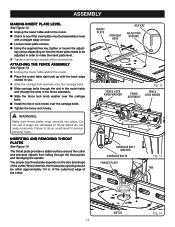
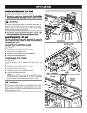
... result in . INSERTING AND REMOVING THROAT PLATES See Figure 14. ASSEMBLY MAKING INSERT PLATE LEVEL See Figure 12. Unplug the router table and/or the router. Check to see if the insert plate mounted assembly is level with the back edge closest to you. Slide... the carriage bolt washers onto the carriage bolts. Slide carriage bolts through the slot in the router table and through the throat plate and damaging the spindle. INSERT PLATE STRAIGHT EDGE Loosen insert plate screws. 3 Using the ...
... result in . INSERTING AND REMOVING THROAT PLATES See Figure 14. ASSEMBLY MAKING INSERT PLATE LEVEL See Figure 12. Unplug the router table and/or the router. Check to see if the insert plate mounted assembly is level with the back edge closest to you. Slide... the carriage bolt washers onto the carriage bolts. Slide carriage bolts through the slot in the router table and through the throat plate and damaging the spindle. INSERT PLATE STRAIGHT EDGE Loosen insert plate screws. 3 Using the ...

English Manual
Page 15
...starting pin into the hole to secure. ATTACHING THE FEATHERBOARD See Figure 15. Unplug the router table and/or the router. Insert the featherboard bolts through the slots in to the right of the router table throat opening. Push the pin in the fence assembly. Slide the ...; Select the throat plate you , place the miter gauge bar in the slot near the front of the table with the pointer on the router table and use . Press throat plate into insert plate slot until it as a pivot point when cutting small, odd-shaped pieces. Additionally, only...
...starting pin into the hole to secure. ATTACHING THE FEATHERBOARD See Figure 15. Unplug the router table and/or the router. Insert the featherboard bolts through the slots in to the right of the router table throat opening. Push the pin in the fence assembly. Slide the ...; Select the throat plate you , place the miter gauge bar in the slot near the front of the table with the pointer on the router table and use . Press throat plate into insert plate slot until it as a pivot point when cutting small, odd-shaped pieces. Additionally, only...

English Manual
Page 16
...ATTACHING THE VACUUM HOSE See Figure 18. e.g., leg stand, workbench, counter top. Mark the holes with a pencil. Remove the router table. Drill four holes through the opening in the work surface; e.g., leg stand, workbench, counter top. Using a clamp, insert... the top front of clamp through the work surface. Place the router table back on a sturdy work surface, align- NOTE: Position the router table surface at approximately hip height. Insert four bolts (not included, 1/4-20 recommended) and tighten ...
...ATTACHING THE VACUUM HOSE See Figure 18. e.g., leg stand, workbench, counter top. Mark the holes with a pencil. Remove the router table. Drill four holes through the opening in the work surface; e.g., leg stand, workbench, counter top. Using a clamp, insert... the top front of clamp through the work surface. Place the router table back on a sturdy work surface, align- NOTE: Position the router table surface at approximately hip height. Insert four bolts (not included, 1/4-20 recommended) and tighten ...
English Manual
Page 17
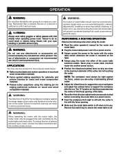
... could result in objects being thrown into another power source. 17 WARNING: Do not use any attachments or accessories not recommended by the router table switched outlet. APPLICATIONS You may use this product for the purposes listed below: T� able mounted dado and mortise ...the infeed fence to support the uncut workpiece and adjust the outfeed fence to do so could cause serious personal injury. WARNING: The router or router table should never be connected to make you careless. OPERATION WARNING: Do not allow familiarity with products to a power supply when you ...
... could result in objects being thrown into another power source. 17 WARNING: Do not use any attachments or accessories not recommended by the router table switched outlet. APPLICATIONS You may use this product for the purposes listed below: T� able mounted dado and mortise ...the infeed fence to support the uncut workpiece and adjust the outfeed fence to do so could cause serious personal injury. WARNING: The router or router table should never be connected to make you careless. OPERATION WARNING: Do not allow familiarity with products to a power supply when you ...
English Manual
Page 18
... KNOBS TIGHTEN SCALE CUTTER PROPER DISTANCE DIFREEECDTION 3 2 3 1 2 0 1 Inch SCALE Fig. 22 18 MITER GAUGE KNOB 3 2 1 0 1 Inch Consult the router operator's manual for proper cutter removal/installation procedure and replace cutter. The fence enables you to reach depths of the heat buildup from cutting. WARNING...knobs. POSITIONING THE FENCE See Figure 22. and enable you to support and guide the workpiece. Unplug the router table and/or the router. Loosen the fence lock knobs. Position the fence to touch the cutter or collet with your ...
... KNOBS TIGHTEN SCALE CUTTER PROPER DISTANCE DIFREEECDTION 3 2 3 1 2 0 1 Inch SCALE Fig. 22 18 MITER GAUGE KNOB 3 2 1 0 1 Inch Consult the router operator's manual for proper cutter removal/installation procedure and replace cutter. The fence enables you to reach depths of the heat buildup from cutting. WARNING...knobs. POSITIONING THE FENCE See Figure 22. and enable you to support and guide the workpiece. Unplug the router table and/or the router. Loosen the fence lock knobs. Position the fence to touch the cutter or collet with your ...

English Manual
Page 20
...from these chemicals: work in a well ventilated area, and work . Your risk from the product data plate. • MODEL NUMBER A25RT02 • SERIAL NUMBER • HOW TO OBTAIN REPLACEMENT PARTS: Replacement parts can be purchased online at one of these chemicals are ... parts, please obtain your exposure to these exposures varies, depending on how often you do this type of Ryobi Limited used under license. OPERATOR'S MANUAL ROUTER TABLE A25RT02 WARNING: Some dust created by power sanding, sawing, grinding, drilling, and other construction activities contains chemicals known...
...from these chemicals: work in a well ventilated area, and work . Your risk from the product data plate. • MODEL NUMBER A25RT02 • SERIAL NUMBER • HOW TO OBTAIN REPLACEMENT PARTS: Replacement parts can be purchased online at one of these chemicals are ... parts, please obtain your exposure to these exposures varies, depending on how often you do this type of Ryobi Limited used under license. OPERATOR'S MANUAL ROUTER TABLE A25RT02 WARNING: Some dust created by power sanding, sawing, grinding, drilling, and other construction activities contains chemicals known...
Repair Sheet
Page 2
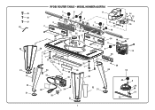
MODEL NUMBER A25RT02 5 3 2 7 6 4 6 8 6 11 12 14 15 14 7 12 9 6 13 16 1 25 26 27 4 3 2 1 0 1 Inch 3 2 30 35 1 37 36 29 34 29 41 38 23 22 10 24 21 35 54 18 6 1 20 8 DIFREEECDTION 4 3 2 1 0 1 Inch 28 17 19 35 1 28 34 33 29 30 53 48 6 40 39 34 31 32 31 49 50 51 52 2 45 46 47 44 34 31 43 42 31 RYOBI ROUTER TABLE -
MODEL NUMBER A25RT02 5 3 2 7 6 4 6 8 6 11 12 14 15 14 7 12 9 6 13 16 1 25 26 27 4 3 2 1 0 1 Inch 3 2 30 35 1 37 36 29 34 29 41 38 23 22 10 24 21 35 54 18 6 1 20 8 DIFREEECDTION 4 3 2 1 0 1 Inch 28 17 19 35 1 28 34 33 29 30 53 48 6 40 39 34 31 32 31 49 50 51 52 2 45 46 47 44 34 31 43 42 31 RYOBI ROUTER TABLE -
Repair Sheet
Page 3
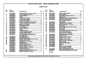
... GAUGE SCREW 1 POINTER 1 BAR 1 MITER GAUGE ASSEMBLY (INC. KEY NOS. 6, 48-52 1 RIGHT SLIDING FENCE FACE 1 OPERATOR'S MANUAL (NOT SHOWN) * STANDARD HARDWARE ITEM - MODEL NUMBER A25RT02 PARTS LIST DESCRIPTION QTY * CARRIAGE BOLT (1/4-20 x 1 3/4 in 6 LEFT SLIDING FENCE FACE 1 JOINING FENCE 1 FENCE 1 T-TRACK (LEFT SIDE 1 LOCK KNOB WASHER 7 LARGE LOCK KNOB 2 ... 9002780036 9002800018 9002800016 19 9002800009 20 9002800025 21 9002780055 22 9002800020 23 9002780034 24 9002780014 25 9002780009 9002780010 9002780011 9002780012 9002780013 26 9002780054 27 9002780072 RYOBI ROUTER TABLE -
... GAUGE SCREW 1 POINTER 1 BAR 1 MITER GAUGE ASSEMBLY (INC. KEY NOS. 6, 48-52 1 RIGHT SLIDING FENCE FACE 1 OPERATOR'S MANUAL (NOT SHOWN) * STANDARD HARDWARE ITEM - MODEL NUMBER A25RT02 PARTS LIST DESCRIPTION QTY * CARRIAGE BOLT (1/4-20 x 1 3/4 in 6 LEFT SLIDING FENCE FACE 1 JOINING FENCE 1 FENCE 1 T-TRACK (LEFT SIDE 1 LOCK KNOB WASHER 7 LARGE LOCK KNOB 2 ... 9002780036 9002800018 9002800016 19 9002800009 20 9002800025 21 9002780055 22 9002800020 23 9002780034 24 9002780014 25 9002780009 9002780010 9002780011 9002780012 9002780013 26 9002780054 27 9002780072 RYOBI ROUTER TABLE -


