English Manual
Page 7
... equipment-grounding conductor. Before using a power product at a considerable distance from the power source, use . The plug must be used. **Ampere rating (on product data plate) 0-2.0 2.1-3.4 3.5-5.0 5.1-7.0 7.1-12.0 12.1-16.0 Cord Length Wire Size (A.W.G.) 25' 16 16 16 16 14 14 50' 16 16 16 14 14 12 100' 16 16 14...
... equipment-grounding conductor. Before using a power product at a considerable distance from the power source, use . The plug must be used. **Ampere rating (on product data plate) 0-2.0 2.1-3.4 3.5-5.0 5.1-7.0 7.1-12.0 12.1-16.0 Cord Length Wire Size (A.W.G.) 25' 16 16 16 16 14 14 50' 16 16 16 14 14 12 100' 16 16 14...
English Manual
Page 8
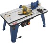
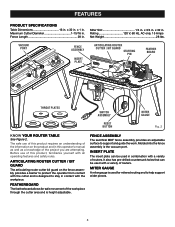
... gauge is designed to support and guide the work. VACUUM PORT FENCE ASSEMBLY INSERT PLATE ARTICULATING ROUTER CUTTER / BIT GUARD STARTING PIN 3 2 1 0 1 Inch FEATHER BOARD inch 3 2 1 0 1 Inch RESE T PUSH THROAT PLATES SWITCH ASSEMBLY RESET BUTTON MITER GAUGE Fig. 2 KNOW YOUR ROUTER TABLE See Figure ...2. x 32 in . FEATHERBOARD The featherboard allows for mitered routing and to help support wider pieces. 8 INSERT PLATE The insert plate can be used for safe movement of the project you are attempting. x 3/4 in . Maximum Cutter Diameter 1-15/16 in ....
... gauge is designed to support and guide the work. VACUUM PORT FENCE ASSEMBLY INSERT PLATE ARTICULATING ROUTER CUTTER / BIT GUARD STARTING PIN 3 2 1 0 1 Inch FEATHER BOARD inch 3 2 1 0 1 Inch RESE T PUSH THROAT PLATES SWITCH ASSEMBLY RESET BUTTON MITER GAUGE Fig. 2 KNOW YOUR ROUTER TABLE See Figure ...2. x 32 in . FEATHERBOARD The featherboard allows for mitered routing and to help support wider pieces. 8 INSERT PLATE The insert plate can be used for safe movement of the project you are attempting. x 3/4 in . Maximum Cutter Diameter 1-15/16 in ....
English Manual
Page 9
STARTING PIN When you are included with the router table. The throat plate provides a stable surface around the cutter and prevents objects from overload. or 2-1/2 in a safe, secure location. TO LOCK YOUR ROUTER TABLE: Press the switch ... ( See Figure 2 ). FEATURES RESET BUTTON See Figure 2. This action will accept either switch box outlet on , press the reset button and then restart. THROAT PLATES Five throat plates are unable to turn OFF ( O ). WARNING: Always remove the switch key when the tool is not in use by children and others. This feature...
STARTING PIN When you are included with the router table. The throat plate provides a stable surface around the cutter and prevents objects from overload. or 2-1/2 in a safe, secure location. TO LOCK YOUR ROUTER TABLE: Press the switch ... ( See Figure 2 ). FEATURES RESET BUTTON See Figure 2. This action will accept either switch box outlet on , press the reset button and then restart. THROAT PLATES Five throat plates are unable to turn OFF ( O ). WARNING: Always remove the switch key when the tool is not in use by children and others. This feature...

English Manual
Page 10
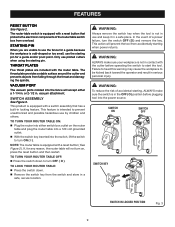
... (2) 18 DIFREEECDTION 23 19 22 3 20 3 2 1 0 1 Inch 17 21 16 15 14 13 12 11 Fig. 4 12. Router Insert Plate Screws (5/16-18 x 3/4 in .) (3) 16. Failure to modify this product or create accessories not recommended for assistance. WARNING: Do not attempt to ...alteration or modification is complete. Table Leg Phillips Head Screw (16) 4. Miter Gauge 18. Router Insert Plate Screws (10-32 x 5/8 in .) (3) 14. Table Top 5. Switch Box Screw (3) 7. Router Insert Plate Screws (10-24 x 5/8 in the packing list are replaced. Featherboard Lock Knobs (2) 24. Fence...
... (2) 18 DIFREEECDTION 23 19 22 3 20 3 2 1 0 1 Inch 17 21 16 15 14 13 12 11 Fig. 4 12. Router Insert Plate Screws (5/16-18 x 3/4 in .) (3) 16. Failure to modify this product or create accessories not recommended for assistance. WARNING: Do not attempt to ...alteration or modification is complete. Table Leg Phillips Head Screw (16) 4. Miter Gauge 18. Router Insert Plate Screws (10-32 x 5/8 in .) (3) 14. Table Top 5. Switch Box Screw (3) 7. Router Insert Plate Screws (10-24 x 5/8 in the packing list are replaced. Featherboard Lock Knobs (2) 24. Fence...
English Manual
Page 11
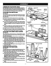
... THE ROUTER TABLE Assembling the router table involves attaching the switch box, the under table guards, the legs, the router/insert plate assembly, the fence assembly, featherboard, throat plate, starting pin, and installing the miter gauge to attach the under table guards. Place the router table upside down ...on a flat surface. Position the under table guards in front of and behind the insert plate. ATTACHING THE SWITCH BOX See Figure 5. The front under table guard will come in a bag with the holes in the table.
... THE ROUTER TABLE Assembling the router table involves attaching the switch box, the under table guards, the legs, the router/insert plate assembly, the fence assembly, featherboard, throat plate, starting pin, and installing the miter gauge to attach the under table guards. Place the router table upside down ...on a flat surface. Position the under table guards in front of and behind the insert plate. ATTACHING THE SWITCH BOX See Figure 5. The front under table guard will come in a bag with the holes in the table.
English Manual
Page 12
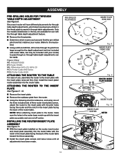
...Remove the throat plate. Determine which router you have and find the pre-drilled pilot hole that matches your router) to pass though so through table adjustments. ASSEMBLY PRE-DRILLING HOLES FOR THROUGH TABLE DEPTH ADJUSTMENT See Figure 8. Figure 8 Key: RD: RIDGID R2930 RY: Ryobi R163K ML: ...Milwaukee 5615-20, 5616-20 PC1: Porter-Cable 890 Series PC2: Porter-Cable 8529 ATTACHING THE ROUTER TO THE TABLE For ease of the router table. INSTALLING THE ROUTER/INSERT PLATE ASSEMBLY See Figure 11. With the insert...
...Remove the throat plate. Determine which router you have and find the pre-drilled pilot hole that matches your router) to pass though so through table adjustments. ASSEMBLY PRE-DRILLING HOLES FOR THROUGH TABLE DEPTH ADJUSTMENT See Figure 8. Figure 8 Key: RD: RIDGID R2930 RY: Ryobi R163K ML: ...Milwaukee 5615-20, 5616-20 PC1: Porter-Cable 890 Series PC2: Porter-Cable 8529 ATTACHING THE ROUTER TO THE TABLE For ease of the router table. INSTALLING THE ROUTER/INSERT PLATE ASSEMBLY See Figure 11. With the insert...

English Manual
Page 13
...x 3/4 in . A2, A4, A6 3 Hitachi M12V Plunge 10-32 x 5/8 in . A1, A3, A5 3 Hitachi KM12VC Fixed 10-32 x 5/8 in . B1, B3 2 Ryobi RE175 Plunge 5/16-18 x 3/4 in . A2, A4, A6 3 Craftsman 17511 Fixed 10-32 x 5/8 in . A2, A4, A6 3 Craftsman 17533 Plunge 5/16-18 x 3/4 in...-18 x 3/4 in . B1, B2, B4 3 Ryobi R163K Fixed 5/16-18 x 3/4 in . A2, A4, A6 3 All identified trademarks and trade names are the property of their respective owners. 13 ASSEMBLY BRAND MODEL BASE TYPE FASTENER SIZE INSERT PLATE HOLES USED NUMBER OF HOLES Bosch 1617 Fixed 10-24 ...
...x 3/4 in . A2, A4, A6 3 Hitachi M12V Plunge 10-32 x 5/8 in . A1, A3, A5 3 Hitachi KM12VC Fixed 10-32 x 5/8 in . B1, B3 2 Ryobi RE175 Plunge 5/16-18 x 3/4 in . A2, A4, A6 3 Craftsman 17511 Fixed 10-32 x 5/8 in . A2, A4, A6 3 Craftsman 17533 Plunge 5/16-18 x 3/4 in...-18 x 3/4 in . B1, B2, B4 3 Ryobi R163K Fixed 5/16-18 x 3/4 in . A2, A4, A6 3 All identified trademarks and trade names are the property of their respective owners. 13 ASSEMBLY BRAND MODEL BASE TYPE FASTENER SIZE INSERT PLATE HOLES USED NUMBER OF HOLES Bosch 1617 Fixed 10-24 ...
English Manual
Page 14
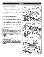
...carriage bolt washers onto the carriage bolts. Slide carriage bolts through the slot in the router table and through the throat plate and damaging the spindle. ATTACHING THE FENCE ASSEMBLY See Figure 13. Unplug the router table and/or the router. ... Inch Fig. 12 FENCE FENCE LOCK KNOBS ASSEMBLY 1 Inch 0 3 2 1 0 WARNING: Make sure throat plates snap securely into place. of the outermost edge of the cutter. INSERT PLATE STRAIGHT EDGE Loosen insert plate screws. 3 Using the supplied hex key, tighten or loosen the adjust- 2 1 0 ing screws ...
...carriage bolt washers onto the carriage bolts. Slide carriage bolts through the slot in the router table and through the throat plate and damaging the spindle. ATTACHING THE FENCE ASSEMBLY See Figure 13. Unplug the router table and/or the router. ... Inch Fig. 12 FENCE FENCE LOCK KNOBS ASSEMBLY 1 Inch 0 3 2 1 0 WARNING: Make sure throat plates snap securely into place. of the outermost edge of the cutter. INSERT PLATE STRAIGHT EDGE Loosen insert plate screws. 3 Using the supplied hex key, tighten or loosen the adjust- 2 1 0 ing screws ...

English Manual
Page 15
... the front edge closest to you are using the starting pin, but the bit guard should be used to the right of the Inch insert plate. NOTE: It is not necessary to secure. Additionally, only use the fence when you , place the miter gauge bar in the fence assembly. ...; Tighten the fence lock knobs. INSERTING THE STARTING PIN See Figure 16. Place the starting pin into place. 3 2 To remove, push throat plate out from1 0 1 the bottom of the router table throat opening. Push the pin in to use piloted cutters whe1n using the starting pin.
... the front edge closest to you are using the starting pin, but the bit guard should be used to the right of the Inch insert plate. NOTE: It is not necessary to secure. Additionally, only use the fence when you , place the miter gauge bar in the fence assembly. ...; Tighten the fence lock knobs. INSERTING THE STARTING PIN See Figure 16. Place the starting pin into place. 3 2 To remove, push throat plate out from1 0 1 the bottom of the router table throat opening. Push the pin in to use piloted cutters whe1n using the starting pin.
English Manual
Page 18
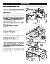
... procedure and replace cutter. OPERATION INSERTING/REMOVING CUTTERS Unplug the router table and/or the router. Remove the router/insert plate assembly. (See Installing Router/Insert Plate Assembly in . and that the workpiece is located between the cutter and the fence. and enable you to support and guide the workpiece...
... procedure and replace cutter. OPERATION INSERTING/REMOVING CUTTERS Unplug the router table and/or the router. Remove the router/insert plate assembly. (See Installing Router/Insert Plate Assembly in . and that the workpiece is located between the cutter and the fence. and enable you to support and guide the workpiece...

English Manual
Page 20
...cement and other masonry products, and • arsenic and chromium from these chemicals: work in a well ventilated area, and work . Ryobi® is a registered trademark of our Authorized Service Centers. • HOW TO LOCATE AN AUTHORIZED SERVICE CENTER: Authorized Service Centers can ...reproductive harm. Replacement parts can be obtained at one of Ryobi Limited used under license. Your risk from chemically-treated lumber. To reduce your model and serial number from the product data plate. • MODEL NUMBER A25RT02 • SERIAL NUMBER • HOW TO OBTAIN REPLACEMENT PARTS...
...cement and other masonry products, and • arsenic and chromium from these chemicals: work in a well ventilated area, and work . Ryobi® is a registered trademark of our Authorized Service Centers. • HOW TO LOCATE AN AUTHORIZED SERVICE CENTER: Authorized Service Centers can ...reproductive harm. Replacement parts can be obtained at one of Ryobi Limited used under license. Your risk from chemically-treated lumber. To reduce your model and serial number from the product data plate. • MODEL NUMBER A25RT02 • SERIAL NUMBER • HOW TO OBTAIN REPLACEMENT PARTS...
Repair Sheet
Page 3
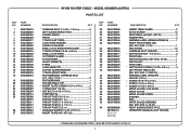
...9002780014 25 9002780009 9002780010 9002780011 9002780012 9002780013 26 9002780054 27 9002780072 RYOBI ROUTER TABLE - MAY BE PURCHASED LOCALLY 3 KEY NOS....LONG HINGE PIN 1 CUTTER GUARD BRACKET 1 T-TRACK (RIGHT SIDE 1 FEATHERBOARD CARRIAGE BOLT (1/4. MODEL NUMBER A25RT02 PARTS LIST DESCRIPTION QTY * CARRIAGE BOLT (1/4-20 x 1 3/4 in 6 LEFT SLIDING FENCE FACE 1 ...in 1 STARTING PIN 1 THROAT PLATE-A (1/2 in 1 THROAT PLATE-B (1 in 1 THROAT PLATE-C (1-3/16 in 1 THROAT PLATE-D (1-1/2 in 1 THROAT PLATE-E (2 in 1 * LEVELING SCREW (1/4-20 x 5/16 in 4 INSERT PLATE (INC. KEY 26 1 KEY...
...9002780014 25 9002780009 9002780010 9002780011 9002780012 9002780013 26 9002780054 27 9002780072 RYOBI ROUTER TABLE - MAY BE PURCHASED LOCALLY 3 KEY NOS....LONG HINGE PIN 1 CUTTER GUARD BRACKET 1 T-TRACK (RIGHT SIDE 1 FEATHERBOARD CARRIAGE BOLT (1/4. MODEL NUMBER A25RT02 PARTS LIST DESCRIPTION QTY * CARRIAGE BOLT (1/4-20 x 1 3/4 in 6 LEFT SLIDING FENCE FACE 1 ...in 1 STARTING PIN 1 THROAT PLATE-A (1/2 in 1 THROAT PLATE-B (1 in 1 THROAT PLATE-C (1-3/16 in 1 THROAT PLATE-D (1-1/2 in 1 THROAT PLATE-E (2 in 1 * LEVELING SCREW (1/4-20 x 5/16 in 4 INSERT PLATE (INC. KEY 26 1 KEY...


