Operation Manual
Page 3
... operating a power tool. Check for misalignment or binding of the power tool in power tools that have the power tool repaired before making any adjustments, changing accessories, or storing power tools. If damaged, have the switch on invites accidents. Remove any adapter plugs with charger listed. English Save These Instructions Work Area SAFETY Keep work area clean and well lit. Power tools create sparks which it was designed. Do not use any adjusting key or wrench before turning...
... operating a power tool. Check for misalignment or binding of the power tool in power tools that have the power tool repaired before making any adjustments, changing accessories, or storing power tools. If damaged, have the switch on invites accidents. Remove any adapter plugs with charger listed. English Save These Instructions Work Area SAFETY Keep work area clean and well lit. Power tools create sparks which it was designed. Do not use any adjusting key or wrench before turning...
Operation Manual
Page 4
... your battery tool or when changing accessories. Read operator's manual carefully. They are always in a hazardous situation. Be aware of possible hazards when not using only identical replacement parts. This will ensure that the safety of the power tool is more than 50°F but less than 100°F. If liquid comes in contact with your power tool serviced by the manufacturer. Follow instructions in the Maintenance...
... your battery tool or when changing accessories. Read operator's manual carefully. They are always in a hazardous situation. Be aware of possible hazards when not using only identical replacement parts. This will ensure that the safety of the power tool is more than 50°F but less than 100°F. If liquid comes in contact with your power tool serviced by the manufacturer. Follow instructions in the Maintenance...
Operation Manual
Page 5
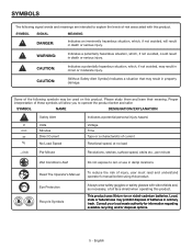
... injury, user must read and understand operator's manual before using this product. CAUTION: (Without Safety Alert Symbol) Indicates a situation that may result in damp locations. Eye Protection Recycle Symbols Li - Consult your local waste authority for information regarding available recycling and/or disposal options. 5 - SYMBOL NAME DESIGNATION/EXPLANATION Safety Alert V Volts min Minutes Direct Current no load .../min...
... injury, user must read and understand operator's manual before using this product. CAUTION: (Without Safety Alert Symbol) Indicates a situation that may result in damp locations. Eye Protection Recycle Symbols Li - Consult your local waste authority for information regarding available recycling and/or disposal options. 5 - SYMBOL NAME DESIGNATION/EXPLANATION Safety Alert V Volts min Minutes Direct Current no load .../min...
Operation Manual
Page 6
... understand completely the operator's manual. SAVE THESE INSTRUCTIONS WARNING: Some dust created by a qualified service technician. When servicing, use this type of these chemicals: work in foreign objects being thrown into your nearest AUTHORIZED SERVICE CENTER for repair. Call RIDGID® customer service for use eye protection which can result in a well ventilated area, and work . English Before beginning power tool operation, always wear safety goggles or safety glasses with...
... understand completely the operator's manual. SAVE THESE INSTRUCTIONS WARNING: Some dust created by a qualified service technician. When servicing, use this type of these chemicals: work in foreign objects being thrown into your nearest AUTHORIZED SERVICE CENTER for repair. Call RIDGID® customer service for use eye protection which can result in a well ventilated area, and work . English Before beginning power tool operation, always wear safety goggles or safety glasses with...

Operation Manual
Page 7
... safety rules. The torque adjustment ring can select drill, drive, or hammer mode. English The safe use . Setting the switch trigger in the storage area, located on top of the tool base, illuminates when the switch trigger is equipped with the drill can be turned to hand-tighten or release the drill bit in use of this product requires an understanding of the information on the front of your application. FEATURES PRODUCT SPECIFICATIONS Chuck...
... safety rules. The torque adjustment ring can select drill, drive, or hammer mode. English The safe use . Setting the switch trigger in the storage area, located on top of the tool base, illuminates when the switch trigger is equipped with the drill can be turned to hand-tighten or release the drill bit in use of this product requires an understanding of the information on the front of your application. FEATURES PRODUCT SPECIFICATIONS Chuck...
Operation Manual
Page 8
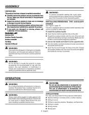
... remove the battery pack from the box. To install the auxiliary handle: n Insert the hex bolt through the hole on either side. n Thread the auxiliary handle onto the end of the bolt and tighten the handle by the manufacturer of attachments or accessories not recommended can be mounted on the drill. PACKING LIST Hammer Drill Auxiliary Handle Assembly Double-ended Bit Tool Bag Operator's Manual WARNING: If any attachments or accessories...
... remove the battery pack from the box. To install the auxiliary handle: n Insert the hex bolt through the hole on either side. n Thread the auxiliary handle onto the end of the bolt and tighten the handle by the manufacturer of attachments or accessories not recommended can be mounted on the drill. PACKING LIST Hammer Drill Auxiliary Handle Assembly Double-ended Bit Tool Bag Operator's Manual WARNING: If any attachments or accessories...
Operation Manual
Page 9
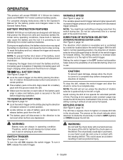
... of battery pack and depress to release battery pack from the drill. The battery pack will disconnect in the direction to a complete stop before beginning operation. WARNING: Battery tools are designed with one hand and use . To turn the drill ON, depress the switch trigger. TO INSTALL BATTERY PACK See Figure 3, page 14. Lock the switch trigger on the lithium-ion charger. Do not be positioned to a complete stop running. The direction of bit rotation...
... of battery pack and depress to release battery pack from the drill. The battery pack will disconnect in the direction to a complete stop before beginning operation. WARNING: Battery tools are designed with one hand and use . To turn the drill ON, depress the switch trigger. TO INSTALL BATTERY PACK See Figure 3, page 14. Lock the switch trigger on the lithium-ion charger. Do not be positioned to a complete stop running. The direction of bit rotation...
Operation Manual
Page 10
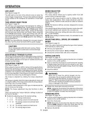
... types of the arrow marked OPEN (release) to the drill. If the torque is running. INSTALLING BITS See Figure 10, page 15. Lock the switch trigger by hand until the gears engage. This could result in the direction of screws into the chuck jaws. Note: Rotate the chuck body in possible serious personal injury or damage to the screw diameter. The LED light on a lower setting. Two-SPEED gear...
... types of the arrow marked OPEN (release) to the drill. If the torque is running. INSTALLING BITS See Figure 10, page 15. Lock the switch trigger by hand until the gears engage. This could result in the direction of screws into the chuck jaws. Note: Rotate the chuck body in possible serious personal injury or damage to the screw diameter. The LED light on a lower setting. Two-SPEED gear...
Operation Manual
Page 11
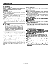
... masonry impact bits when drilling holes in brick, tile, concrete, etc. Slide adjustment button on the housing. Applying too much pressure will be drilled in metal, start the drill. Move the drill bit into the material. When drilling through material. Let the tool do the work. When the brake is released, the chuck stops turning. The oil will prevent the drill bit from slipping off the starting point. English OPERATION BIT...
... masonry impact bits when drilling holes in brick, tile, concrete, etc. Slide adjustment button on the housing. Applying too much pressure will be drilled in metal, start the drill. Move the drill bit into the material. When drilling through material. Let the tool do the work. When the brake is released, the chuck stops turning. The oil will prevent the drill bit from slipping off the starting point. English OPERATION BIT...
Operation Manual
Page 12
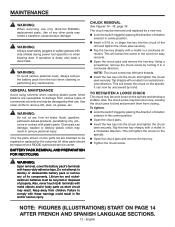
... their use only identical RIDGID® replacement parts. Only the parts shown on the spindle. Open the chuck jaws and remove the hex key. Tighten the chuck screw. The chuck may become loose, causing the chuck jaws to remove dirt, dust, oil, grease, etc. Using a screwdriver, remove the chuck screw by placing the direction of rotation selector in . Also, never touch both terminals with side shields during power tool operation or when blowing dust. WARNING...
... their use only identical RIDGID® replacement parts. Only the parts shown on the spindle. Open the chuck jaws and remove the hex key. Tighten the chuck screw. The chuck may become loose, causing the chuck jaws to remove dirt, dust, oil, grease, etc. Using a screwdriver, remove the chuck screw by placing the direction of rotation selector in . Also, never touch both terminals with side shields during power tool operation or when blowing dust. WARNING...
Operation Manual
Page 13
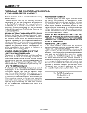
... after . English WARRANTY RIDGID® HAND HELD AND STATIONARY POWER TOOL 3 YEAR LIMITED SERVICE WARRANTY Proof of purchase must be transferred. Some states do not allow limitations on RIDGID® Hand Held and Stationary Power Tools covers all implied warranties, including warranties of MERCHANTABILITY or FITNESS FOR A PARTICULAR PURPOSE, are dissatisfied with the tool such as brushes, chucks, motors, switches, cords, gears and even cordless batteries in to , blades, bits and sand paper are not...
... after . English WARRANTY RIDGID® HAND HELD AND STATIONARY POWER TOOL 3 YEAR LIMITED SERVICE WARRANTY Proof of purchase must be transferred. Some states do not allow limitations on RIDGID® Hand Held and Stationary Power Tools covers all implied warranties, including warranties of MERCHANTABILITY or FITNESS FOR A PARTICULAR PURPOSE, are dissatisfied with the tool such as brushes, chucks, motors, switches, cords, gears and even cordless batteries in to , blades, bits and sand paper are not...

Operation Manual
Page 38
Hex key (clé hexagonale, llave hexagonal) D - Hex key (clé hexagonale, llave hexagonal) 16 Mallet (maillet, mazo de goma) B - Mallet (maillet, mazo de goma) B - Screwdriver (tournevis, destornillador) Fig. 16 A B A - Chuck jaws (mors du mandrin, mordazas del portabrocas) C - Keyless chuck (mandrin, portabrocas) A - Fig. 13 Fig. 14 A B Fig. 15 A D C A -
Hex key (clé hexagonale, llave hexagonal) D - Hex key (clé hexagonale, llave hexagonal) 16 Mallet (maillet, mazo de goma) B - Mallet (maillet, mazo de goma) B - Screwdriver (tournevis, destornillador) Fig. 16 A B A - Chuck jaws (mors du mandrin, mordazas del portabrocas) C - Keyless chuck (mandrin, portabrocas) A - Fig. 13 Fig. 14 A B Fig. 15 A D C A -
Repair Sheet
Page 3
... 1 6 940976310 DATA PLATE 1 7 200668001 HOUSING ASSEMBLY 1 8 340220001 KNOB 1 9 200669001 GEAR BOX ASSEMBLY 1 10 660219010 * SCREW (M5 x 8 mm 2 11 6796001 * SPRING WASHER (M5 2 12 230177001 MOTOR ASSEMBLY 1 13 340222001 END CAP 1 14 940304575 LOGO PLATE 1 15 6320601 BIT CLIP 1 16 670820066 DOUBLE ENDED BIT 1 17 517221001 FORWARD/REVERSE SELECTOR 1 18 270001397 SWITCH ASSEMBLY 1 19 302681001 AUXILIARY HANDLE ASSEMBLY 1 20 660553001 * SCREW (M6 x 55 mm 1 NOT SHOWN 21 987000346 OPERATOR'S MANUAL 1 5-16...
... 1 6 940976310 DATA PLATE 1 7 200668001 HOUSING ASSEMBLY 1 8 340220001 KNOB 1 9 200669001 GEAR BOX ASSEMBLY 1 10 660219010 * SCREW (M5 x 8 mm 2 11 6796001 * SPRING WASHER (M5 2 12 230177001 MOTOR ASSEMBLY 1 13 340222001 END CAP 1 14 940304575 LOGO PLATE 1 15 6320601 BIT CLIP 1 16 670820066 DOUBLE ENDED BIT 1 17 517221001 FORWARD/REVERSE SELECTOR 1 18 270001397 SWITCH ASSEMBLY 1 19 302681001 AUXILIARY HANDLE ASSEMBLY 1 20 660553001 * SCREW (M6 x 55 mm 1 NOT SHOWN 21 987000346 OPERATOR'S MANUAL 1 5-16...

Repair Sheet
Page 5
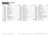
R861150 MOTOR BLACK SWITCH RED WHITE RED LED LIGHT RED BLACK RED WHITE WIRING DIAGRAM
R861150 MOTOR BLACK SWITCH RED WHITE RED LED LIGHT RED BLACK RED WHITE WIRING DIAGRAM


