
English Manual
Page 2
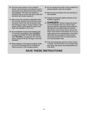
... WARNING DECAL PLACEMENT 2 IMPORTANT PRECAUTIONS 3 BEFORE YOU BEGIN 7 PART IDENTIFICATION CHART 8 ASSEMBLY 9 THE CHEST HEART RATE MONITOR 17 OPERATION AND ADJUSTMENT 18 HOW TO FOLD AND MOVE THE TREADMILL 26 TROUBLESHOOTING 27 EXERCISE GUIDELINES 30 PART LIST 31 EXPLODED DRAWING 32 ORDERING REPLACEMENT PARTS ... WARRANTY Back Cover WARNING DECAL PLACEMENT This drawing shows the locations of Reebok. Apply the decal in the location shown. Note: The decals may not be shown at actual size. REEBOK and the Vector Logo are registered trademarks and service marks of the warning...
... WARNING DECAL PLACEMENT 2 IMPORTANT PRECAUTIONS 3 BEFORE YOU BEGIN 7 PART IDENTIFICATION CHART 8 ASSEMBLY 9 THE CHEST HEART RATE MONITOR 17 OPERATION AND ADJUSTMENT 18 HOW TO FOLD AND MOVE THE TREADMILL 26 TROUBLESHOOTING 27 EXERCISE GUIDELINES 30 PART LIST 31 EXPLODED DRAWING 32 ORDERING REPLACEMENT PARTS ... WARRANTY Back Cover WARNING DECAL PLACEMENT This drawing shows the locations of Reebok. Apply the decal in the location shown. Note: The decals may not be shown at actual size. REEBOK and the Vector Logo are registered trademarks and service marks of the warning...
English Manual
Page 4
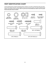
...heart rate monitor is properly assembled. (See ASSEMBLY on page 9 and HOW TO FOLD AND MOVE THE TREADMILL on page 26.) You must be performed by an authorized ser- Do not attempt to move the treadmill. 23. Inspect and properly tighten all parts of the treadmill by an authorized service ...latch is not in the storage position. 24. SAVE THESE INSTRUCTIONS 4 Servicing other than the procedures in general. 21. Never leave the treadmill unattended while it is not a medical device. Never insert any opening on page 7 for the location of heart rate readings. Always ...
...heart rate monitor is properly assembled. (See ASSEMBLY on page 9 and HOW TO FOLD AND MOVE THE TREADMILL on page 26.) You must be performed by an authorized ser- Do not attempt to move the treadmill. 23. Inspect and properly tighten all parts of the treadmill by an authorized service ...latch is not in the storage position. 24. SAVE THESE INSTRUCTIONS 4 Servicing other than the procedures in general. 21. Never leave the treadmill unattended while it is not a medical device. Never insert any opening on page 7 for the location of heart rate readings. Always ...
English Manual
Page 8
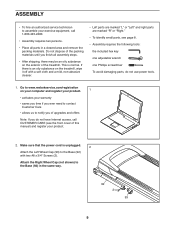
...;-4 3/8" x 1 3/4" Bolt (6)–-1 3/8" x 2" Bolt (3)–-1 3/8" x 2 3/4" Screw (7)–-4 8 The number in the hardware kit, check to identify small parts used for assembly. The number following the key number is the quantity used for assembly. PART IDENTIFICATION CHART Use the drawings below each drawing is the key number of the part, from the PART LIST...
...;-4 3/8" x 1 3/4" Bolt (6)–-1 3/8" x 2" Bolt (3)–-1 3/8" x 2 3/4" Screw (7)–-4 8 The number in the hardware kit, check to identify small parts used for assembly. The number following the key number is the quantity used for assembly. PART IDENTIFICATION CHART Use the drawings below each drawing is the key number of the part, from the PART LIST...
English Manual
Page 9
... there is an oily substance on the treadmill, wipe it off with two #8 x 3/4" Screws (2). Go to www.reebokservice.com/registration on the exterior of this manual) and register your exercise equipment, call 1-800-445-2480. •• Assembly requires two persons. •• Place all assembly steps. •• After shipping, there may...
... there is an oily substance on the treadmill, wipe it off with two #8 x 3/4" Screws (2). Go to www.reebokservice.com/registration on the exterior of this manual) and register your exercise equipment, call 1-800-445-2480. •• Assembly requires two persons. •• Place all assembly steps. •• After shipping, there may...
English Manual
Page 13
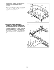
... four Screws. 104 9 81 9 85 13 Tighten all four #10 x 3/4" Screws (9) about halfway into the Handrails (81, 85). 9. Discard the eight Screws. 9 C C 104 98 C C C Console Assembly 10. Then, slide the Crossbar as far forward as shown. Remove the eight indicated Screws (C). Set the console...
... four Screws. 104 9 81 9 85 13 Tighten all four #10 x 3/4" Screws (9) about halfway into the Handrails (81, 85). 9. Discard the eight Screws. 9 C C 104 98 C C C Console Assembly 10. Then, slide the Crossbar as far forward as shown. Remove the eight indicated Screws (C). Set the console...

English Manual
Page 14
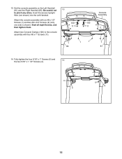
... they do not, turn one connector and try again. Then, remove the wire tie from the console assembly to the Console Ground Wire (99) and insert the wires into place. Connect the Upright Wire (76...console wire. The connectors should slide together easily and snap into the hole in the console assembly. 12 Hole 99 Ground Wire Console Assembly Console Wire 76 Console Wire 76 Wire Tie 81 14 11. With the help of a ...second person, hold the console assembly near the Left Handrail (81). See the inset drawing. Connect the ground wire from the ...
... they do not, turn one connector and try again. Then, remove the wire tie from the console assembly to the Console Ground Wire (99) and insert the wires into place. Connect the Upright Wire (76...console wire. The connectors should slide together easily and snap into the hole in the console assembly. 12 Hole 99 Ground Wire Console Assembly Console Wire 76 Console Wire 76 Wire Tie 81 14 11. With the help of a ...second person, hold the console assembly near the Left Handrail (81). See the inset drawing. Connect the ground wire from the ...
English Manual
Page 15
... the Left Handrail (81) and the Right Handrail (85). Attach the console assembly with four #8 x 1" Screws (11). 1 1 1 85 Console Assembly 2 1 81 14. Start all eight Screws, and then tighten them. 100 100 11 11 Attach two Console Clamps (100) to pinch any wires. 13. Fully ... (5) and 14 the two 5/16" x 1 1/2" Screws (4). 4 5 5 4 15 Insert the excess Upright Wire (not shown) into the Left Handrail. Be careful not 13 to the console assembly with six #8 x 1/2" Screws (1) and two #8 x 3/4" Screws (2) (only one side is shown).
... the Left Handrail (81) and the Right Handrail (85). Attach the console assembly with four #8 x 1" Screws (11). 1 1 1 85 Console Assembly 2 1 81 14. Start all eight Screws, and then tighten them. 100 100 11 11 Attach two Console Clamps (100) to pinch any wires. 13. Fully ... (5) and 14 the two 5/16" x 1 1/2" Screws (4). 4 5 5 4 15 Insert the excess Upright Wire (not shown) into the Left Handrail. Be careful not 13 to the console assembly with six #8 x 1/2" Screws (1) and two #8 x 3/4" Screws (2) (only one side is shown).
English Manual
Page 31
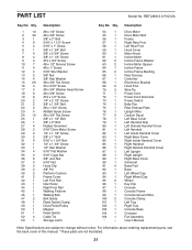
... Left Wheel Cap Right Wheel Cap Wheel Key Clip Console Console Frame Console Ground Wire Console Clamp Left Tray Right Tray Console Base Crossbar Fan Assembly User’'s Manual Note: Specications are not illustrated. 31 Qty. 1 10 2 40 3 1 4 6 5 4 6 1 7 4 8 4 9 4 10 7 11 4 12 4 13 2 14 4 15 29 16 4 17 5 18 6 19...
... Left Wheel Cap Right Wheel Cap Wheel Key Clip Console Console Frame Console Ground Wire Console Clamp Left Tray Right Tray Console Base Crossbar Fan Assembly User’'s Manual Note: Specications are not illustrated. 31 Qty. 1 10 2 40 3 1 4 6 5 4 6 1 7 4 8 4 9 4 10 7 11 4 12 4 13 2 14 4 15 29 16 4 17 5 18 6 19...