
English Manual
Page 6
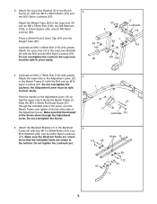
... threads of the Screw show through the indicated side of the Lever, over the Bench Frame, and tighten it into the other side of the Adjustment Lever. Do not overtighten the Screw. 1 97 11 27 Lubricate 110 5. Press a 25mm Round Outer Cap (94) onto the Weight Tube (25). Do not ... (113) with the Bolt and an M10 Nylon Locknut (97). the Adjustment Lever must be able to the bottom. 3. Attach the Backrest Bracket (7) to the Bench 3 Frame (1) with four M10 x 45mm Bolts (112), four M10 Washers (99), and four M10 Nylon Locknuts (97). Holes 8 ed so that the upper ...
... threads of the Screw show through the indicated side of the Lever, over the Bench Frame, and tighten it into the other side of the Adjustment Lever. Do not overtighten the Screw. 1 97 11 27 Lubricate 110 5. Press a 25mm Round Outer Cap (94) onto the Weight Tube (25). Do not ... (113) with the Bolt and an M10 Nylon Locknut (97). the Adjustment Lever must be able to the bottom. 3. Attach the Backrest Bracket (7) to the Bench 3 Frame (1) with four M10 x 45mm Bolts (112), four M10 Washers (99), and four M10 Nylon Locknuts (97). Holes 8 ed so that the upper ...
English Manual
Page 8
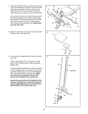
... side. 8 6 104 41 69 Numbers 99 97 99 99 75 113 99 46 99 108 Wet both sides of the Pad Tube with soapy water. Press two 19mm Square Inner Caps (19) into the Pad Tube. Attach a Guide Bar (41) to the Curl Post (6) with an M10 x 50mm Screw (108) and... an M10 Washer (99). Press two 19mm Square Inner Caps (19) into the Pad Tube. Attach the Curl Pad (16) to the Rack Foot (46) with 10 two M6 x 16mm...
... side. 8 6 104 41 69 Numbers 99 97 99 99 75 113 99 46 99 108 Wet both sides of the Pad Tube with soapy water. Press two 19mm Square Inner Caps (19) into the Pad Tube. Attach a Guide Bar (41) to the Curl Post (6) with an M10 x 50mm Screw (108) and... an M10 Washer (99). Press two 19mm Square Inner Caps (19) into the Pad Tube. Attach the Curl Pad (16) to the Rack Foot (46) with 10 two M6 x 16mm...
English Manual
Page 11
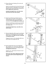
... (40) in the same manner. 19 50 20 116 40 99 97 99 116 74 49 108 99 41 99 49 97 99 36 21. Press a Round Joint Bushing (74) into the Left Barbell Glider (51). Assemble the Right Frame Joint (50) in the same manner. 20.
... (40) in the same manner. 19 50 20 116 40 99 97 99 116 74 49 108 99 41 99 49 97 99 36 21. Press a Round Joint Bushing (74) into the Left Barbell Glider (51). Assemble the Right Frame Joint (50) in the same manner. 20.
English Manual
Page 13
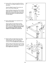
... are set inside the hex holes in the Rear Upright. Orient the Weight Carriage (71) as shown and slide it onto the Rear Upright (38). Press a 60mm Square Inner Cap (65) into 25 the bracket on the bottom. 26. Attach the Rear Top Frame (39) to the Center Upright (37) with...
... are set inside the hex holes in the Rear Upright. Orient the Weight Carriage (71) as shown and slide it onto the Rear Upright (38). Press a 60mm Square Inner Cap (65) into 25 the bracket on the bottom. 26. Attach the Rear Top Frame (39) to the Center Upright (37) with...
English Manual
Page 20
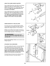
... Round Inner Cap (23) into a Weight Adapter (60). Press a 48mm Round Inner Cap (23) into the Olympic Adapter (24). Attach the Weight Adapter to the Lat Cable (81) with two Cable Clips. Make sure ...
... Round Inner Cap (23) into a Weight Adapter (60). Press a 48mm Round Inner Cap (23) into the Olympic Adapter (24). Attach the Weight Adapter to the Lat Cable (81) with two Cable Clips. Make sure ...


