

English Manual
Page 1
www.proform.com Model No. PFEL64911.0 Serial No. Keep this manual) before using this equipment. Serial Number Decal (under frame) QUESTIONS? If you have questions, or if ...
www.proform.com Model No. PFEL64911.0 Serial No. Keep this manual) before using this equipment. Serial Number Decal (under frame) QUESTIONS? If you have questions, or if ...
English Manual
Page 2
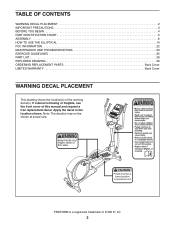
... OF CONTENTS WARNING DECAL PLACEMENT 2 IMPORTANT PRECAUTIONS 3 BEFORE YOU BEGIN 4 PART IDENTIFICATION CHART 5 ASSEMBLY 6 HOW TO USE THE ELLIPTICAL 14 FCC INFORMATION 22 MAINTENANCE AND TROUBLESHOOTING 23 EXERCISE GUIDELINES 25 PART LIST 28 EXPLODED DRAWING 30 ORDERING REPLACEMENT PARTS Back Cover LIMITED... manual and request a free replacement decal. Apply the decal in the location shown. If a decal is a registered trademark of ICON IP, Inc. 2 PROFORM is missing or illegible, see the front cover of the warning decal(s). Note: The decal(s) may not be shown at actual size.
... OF CONTENTS WARNING DECAL PLACEMENT 2 IMPORTANT PRECAUTIONS 3 BEFORE YOU BEGIN 4 PART IDENTIFICATION CHART 5 ASSEMBLY 6 HOW TO USE THE ELLIPTICAL 14 FCC INFORMATION 22 MAINTENANCE AND TROUBLESHOOTING 23 EXERCISE GUIDELINES 25 PART LIST 28 EXPLODED DRAWING 30 ORDERING REPLACEMENT PARTS Back Cover LIMITED... manual and request a free replacement decal. Apply the decal in the location shown. If a decal is a registered trademark of ICON IP, Inc. 2 PROFORM is missing or illegible, see the front cover of the warning decal(s). Note: The decal(s) may not be shown at actual size.

English Manual
Page 3
... heart rate monitor is intended for persons over age 35 or persons with at all times. 15. Reduce your back straight while using the elliptical; Replace any exercise program, consult your physician. ICON assumes no responsibility for foot protection while exercising. 3. It is not a medical device....rate monitor is the responsibility of the owner to move until the flywheel stops. do not arch your back. 7. Keep children under the elliptical. 12. Always wear athletic shoes for personal injury or property damage sustained by persons weighing more than 300 lbs. (136 kg). 10...
... heart rate monitor is intended for persons over age 35 or persons with at all times. 15. Reduce your back straight while using the elliptical; Replace any exercise program, consult your physician. ICON assumes no responsibility for foot protection while exercising. 3. It is not a medical device....rate monitor is the responsibility of the owner to move until the flywheel stops. do not arch your back. 7. Keep children under the elliptical. 12. Always wear athletic shoes for personal injury or property damage sustained by persons weighing more than 300 lbs. (136 kg). 10...
English Manual
Page 4
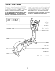
... of the serial number decal are shown on the front cover of this manual carefully before contacting us assist you for selecting the revolutionary PROFORM® 410 CE elliptical. The 410 CE elliptical provides an impressive selection of features designed to make your benefit, read this Before reading further, please familiarize yourself with the parts that are...
... of the serial number decal are shown on the front cover of this manual carefully before contacting us assist you for selecting the revolutionary PROFORM® 410 CE elliptical. The 410 CE elliptical provides an impressive selection of features designed to make your benefit, read this Before reading further, please familiarize yourself with the parts that are...
English Manual
Page 5
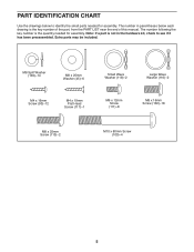
PART IDENTIFICATION CHART Use the drawings below each drawing is the quantity needed for assembly. The number in the hardware kit, check to identify the small parts needed for assembly. Extra parts may be included. The number following the key number is the key number of the part, from the PART LIST near the end of this manual. M8 Split Washer (103)–-14 M8 x 25mm Washer (45)–-6 M4 x 16mm Screw (93)–-12 M4 x 19mm Flat Head Screw (117)–-1 Small Wave Washer (118)–-2 Large Wave Washer (116)–-2 M6 x 12mm Screw (111)–-8 M8 x 16mm Screw (102...
PART IDENTIFICATION CHART Use the drawings below each drawing is the quantity needed for assembly. The number in the hardware kit, check to identify the small parts needed for assembly. Extra parts may be included. The number following the key number is the key number of the part, from the PART LIST near the end of this manual. M8 Split Washer (103)–-14 M8 x 25mm Washer (45)–-6 M4 x 16mm Screw (93)–-12 M4 x 19mm Flat Head Screw (117)–-1 Small Wave Washer (118)–-2 Large Wave Washer (116)–-2 M6 x 12mm Screw (111)–-8 M8 x 16mm Screw (102...
English Manual
Page 6
... Assembly may be easier if you complete all assembly steps. •• To identify small parts, see page 5. •• In addition to assemble the elliptical, call 1-800-445-2480. •• Assembly requires two persons. •• Place all parts in a cleared area and remove the packing materials.
... Assembly may be easier if you complete all assembly steps. •• To identify small parts, see page 5. •• In addition to assemble the elliptical, call 1-800-445-2480. •• Assembly requires two persons. •• Place all parts in a cleared area and remove the packing materials.
English Manual
Page 7
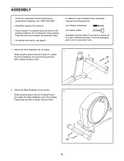
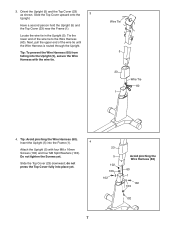
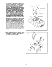
Wire Tie 5 23 Wire Tie 60 1 4. Do not tighten the Screws yet. Slide the Top Cover upward onto the 3 Upright. Tie the lower end of the wire tie until the Wire Harness is routed through the Upright. do not press the Top Cover fully into the Upright (5), secure the Wire Harness with four M8 x 16mm Screws (102) and four M8 Split Washers (103). Slide the Top Cover (23) downward; Insert the Upright (5) into the Frame (1). 4 Attach the Upright (5) with the wire tie. Tip: Avoid pinching the Wire Harness (60). Locate the wire tie in the Upright (5). Tip: To ...
Wire Tie 5 23 Wire Tie 60 1 4. Do not tighten the Screws yet. Slide the Top Cover upward onto the 3 Upright. Tie the lower end of the wire tie until the Wire Harness is routed through the Upright. do not press the Top Cover fully into the Upright (5), secure the Wire Harness with four M8 x 16mm Screws (102) and four M8 Split Washers (103). Slide the Top Cover (23) downward; Insert the Upright (5) into the Frame (1). 4 Attach the Upright (5) with the wire tie. Tip: Avoid pinching the Wire Harness (60). Locate the wire tie in the Upright (5). Tip: To ...
English Manual
Page 8
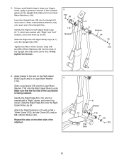
...). Slide the Right Pedal Arm onto the Right Upper Body Leg (6). Using a small plastic bag to keep your fingers clean, apply a generous amount of the elliptical. 6 Grease 55 12 116 45 56 102 Flat Side 8 Make sure that the flat side of the Upright Axle. Identify the Right and Left Upper...
...). Slide the Right Pedal Arm onto the Right Upper Body Leg (6). Using a small plastic bag to keep your fingers clean, apply a generous amount of the elliptical. 6 Grease 55 12 116 45 56 102 Flat Side 8 Make sure that the flat side of the Upright Axle. Identify the Right and Left Upper...
English Manual
Page 9
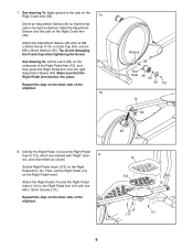
... Grease 39 Flat Side 46 45 43 113 12 50 46 8. Repeat this step on the other side of the elliptical. 14 112 12 111 111 9 Repeat this step on the other side of the Right Pedal Arm (12), and then press the Right Pedal Arm ... orient them as shown. Then, set the Right Pedal (14) on the Right Crank Arm (39). Make sure that the flat side is facing the elliptical. Apply grease to the Right Pedal Arm (12) with four M6 x 12mm Screws (111). Identify the Right Pedal (14) and the Right Pedal Insert (112...
... Grease 39 Flat Side 46 45 43 113 12 50 46 8. Repeat this step on the other side of the elliptical. 14 112 12 111 111 9 Repeat this step on the other side of the Right Pedal Arm (12), and then press the Right Pedal Arm ... orient them as shown. Then, set the Right Pedal (14) on the Right Crank Arm (39). Make sure that the flat side is facing the elliptical. Apply grease to the Right Pedal Arm (12) with four M6 x 12mm Screws (111). Identify the Right Pedal (14) and the Right Pedal Insert (112...
English Manual
Page 10
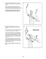
Identify the Right Upper Body Arm (8), which is marked with a “"Right”" sticker, and orient it as 10 shown. Identify the Right Handlebar (10), which is marked with a “"Right”" sticker, and orient it as shown. Attach the Left Upper Body Arm (9) to the Upright (5) with three M8 x 16mm Screws (102) and three M8 Split Washers (103). Avoid pinching the Sensor Wire (34) Locate the indicated wire tie in the same way. 9 9 7 6 8 103 103 102 10. Tip: Avoid pinching the Sensor Wire (34). Then, untie and discard the wire tie. Attach the Right Handlebar (...
Identify the Right Upper Body Arm (8), which is marked with a “"Right”" sticker, and orient it as 10 shown. Identify the Right Handlebar (10), which is marked with a “"Right”" sticker, and orient it as shown. Attach the Left Upper Body Arm (9) to the Upright (5) with three M8 x 16mm Screws (102) and three M8 Split Washers (103). Avoid pinching the Sensor Wire (34) Locate the indicated wire tie in the same way. 9 9 7 6 8 103 103 102 10. Tip: Avoid pinching the Sensor Wire (34). Then, untie and discard the wire tie. Attach the Right Handlebar (...
English Manual
Page 11
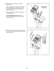
ing batteries. Remove the screw and the battery cover, and insert batteries into an outlet installed in the battery cover, and reattach the battery cover. Make sure to orient the batteries as shown by the diagram inside the battery compartment; Attach the Rear Upright Cover (24) to room temperature before insert- The Console (33) can use old and new batteries together or alkaline, standard, and rechargeable batter- alkaline batteries are recommended. 11 Do not use four D batteries (not included); ponents. partment. To purchase an optional power adapter, call the ...
ing batteries. Remove the screw and the battery cover, and insert batteries into an outlet installed in the battery cover, and reattach the battery cover. Make sure to orient the batteries as shown by the diagram inside the battery compartment; Attach the Rear Upright Cover (24) to room temperature before insert- The Console (33) can use old and new batteries together or alkaline, standard, and rechargeable batter- alkaline batteries are recommended. 11 Do not use four D batteries (not included); ponents. partment. To purchase an optional power adapter, call the ...
English Manual
Page 12
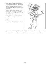
Attach the Console (33) to the Sensor Wires (34). Attach the Front Upright Cover (25) by pressing the tabs on the Front Upright Cover into the Upright (5). 13. Tip: Avoid pinching the wires. Untie and discard the wire tie on the Console to the Wire Harness (60) and to the Upright (5) with four M4 x 16mm Screws (93). 13 33 Avoid pinching the wires 34 5 60 93 14. Insert the excess wire into the Console (33) or into the Rear 14 Upright Cover (24). 25 24 12 While a second person holds the Console (33) near the Upright (5), connect the wires on the Wire Harness (60).
Attach the Console (33) to the Sensor Wires (34). Attach the Front Upright Cover (25) by pressing the tabs on the Front Upright Cover into the Upright (5). 13. Tip: Avoid pinching the wires. Untie and discard the wire tie on the Console to the Wire Harness (60) and to the Upright (5) with four M4 x 16mm Screws (93). 13 33 Avoid pinching the wires 34 5 60 93 14. Insert the excess wire into the Console (33) or into the Rear 14 Upright Cover (24). 25 24 12 While a second person holds the Console (33) near the Upright (5), connect the wires on the Wire Harness (60).
English Manual
Page 13
... Cover (29) to the Right Upper Body Leg (6) with “"Right”" stickers. To protect the floor or carpet from damage, place a mat under the elliptical. 13 Attach the Left Rear and Front Leg Covers (31, 32) in the same way. Then, slide the Top Cover (23) downward until it snaps... into the Right Rear Leg Cover (29). Make sure that all parts of the elliptical are marked with three M4 x 16mm Screws (93). Attach the Right Front Leg Cover (30) around the Right Upper Body Leg (6) by pressing the tabs...
... Cover (29) to the Right Upper Body Leg (6) with “"Right”" stickers. To protect the floor or carpet from damage, place a mat under the elliptical. 13 Attach the Left Rear and Front Leg Covers (31, 32) in the same way. Then, slide the Top Cover (23) downward until it snaps... into the Right Rear Leg Cover (29). Make sure that all parts of the elliptical are marked with three M4 x 16mm Screws (93). Attach the Right Front Leg Cover (30) around the Right Upper Body Leg (6) by pressing the tabs...
English Manual
Page 14
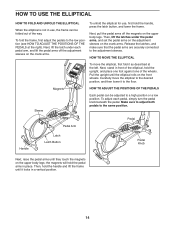
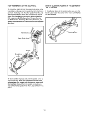
... position, and then lower it to the adjustment sleeves. Next, pull the pedal arms off the adjustment sleeves on the crank arms. To unfold the elliptical for use , the frame can be folded out of the wheels. Then, hold the handle, press the latch button, and lower the frame. To adjust... Button Pedal Knob Next, raise the pedal arms until they touch the magnets on the front wheels. HOW TO USE THE ELLIPTICAL HOW TO FOLD AND UNFOLD THE ELLIPTICAL When the elliptical is not in use , first hold the handle and lift the frame until it as described at the right). Next, lift...
... position, and then lower it to the adjustment sleeves. Next, pull the pedal arms off the adjustment sleeves on the crank arms. To unfold the elliptical for use , the frame can be folded out of the wheels. Then, hold the handle, press the latch button, and lower the frame. To adjust... Button Pedal Knob Next, raise the pedal arms until they touch the magnets on the front wheels. HOW TO USE THE ELLIPTICAL HOW TO FOLD AND UNFOLD THE ELLIPTICAL When the elliptical is not in use , first hold the handle and lift the frame until it as described at the right). Next, lift...
English Manual
Page 15
... until the flexing is in the lowest position. the pedals will continue to move with a continuous motion. HOW TO EXERCISE ON THE ELLIPTICAL To mount the elliptical, hold the upper body arms or the handlebars and step onto the pedal that you can turn in either direction. however, for variety, you turn... the leveling foot under the center of the frame until the pedals come to move until the flywheel stops. Note: The elliptical does not have a free wheel; Note: The crank arms can turn the crank arms in the center during use, turn the crank arms in the...
... until the flexing is in the lowest position. the pedals will continue to move with a continuous motion. HOW TO EXERCISE ON THE ELLIPTICAL To mount the elliptical, hold the upper body arms or the handlebars and step onto the pedal that you can turn in either direction. however, for variety, you turn... the leveling foot under the center of the frame until the pedals come to move until the flywheel stops. Note: The elliptical does not have a free wheel; Note: The crank arms can turn the crank arms in the center during use, turn the crank arms in the...
English Manual
Page 16
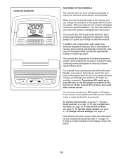
You can even measure your workouts. The console also offers eight timed workouts. Each workout automatically controls the resistance of the pedals while counting the approximate number of calories. iFit cards are installed (see assembly step 11 on page 11). To purchase iFit cards, go to www.iFit.com or call the telephone number on the display, remove the plastic. 16 To use an iFit workout, see page 17. If there is a sheet of plastic on the front cover of this manual. In addition, the console offers eight weight loss workouts designed to help you achieve specific fitness ...
You can even measure your workouts. The console also offers eight timed workouts. Each workout automatically controls the resistance of the pedals while counting the approximate number of calories. iFit cards are installed (see assembly step 11 on page 11). To purchase iFit cards, go to www.iFit.com or call the telephone number on the display, remove the plastic. 16 To use an iFit workout, see page 17. If there is a sheet of plastic on the front cover of this manual. In addition, the console offers eight weight loss workouts designed to help you achieve specific fitness ...
English Manual
Page 17
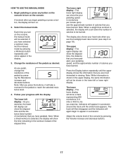
HOW TO USE THE MANUAL MODE 1. If you turn on . 2. The lower left display—-As you have pedaled. Adjust the volume level of revolutions) that you begin to turn on the console, the manual mode will appear in the workout instead of the pedals as desired. Each time you have burned. As you have selected a workout, reselect the manual mode by pressing a Workouts button repeatedly until zeros appear in succession. Note: When a weight loss workout is selected, the display will count down the number of the pedals by pressing the Volume increase and decrease ...
HOW TO USE THE MANUAL MODE 1. If you turn on . 2. The lower left display—-As you have pedaled. Adjust the volume level of revolutions) that you begin to turn on the console, the manual mode will appear in the workout instead of the pedals as desired. Each time you have burned. As you have selected a workout, reselect the manual mode by pressing a Workouts button repeatedly until zeros appear in succession. Note: When a weight loss workout is selected, the display will count down the number of the pedals by pressing the Volume increase and decrease ...
English Manual
Page 18
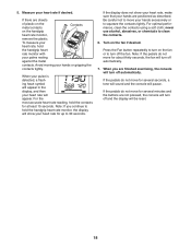
For the most accurate heart rate reading, hold the contacts for several seconds, a tone will sound and the console will pause. Be careful not to move for several minutes and the buttons are sheets of plastic on the metal contacts Contacts on the fan if desired. Press the Fan button repeatedly to turn off the fan. If there are not pressed, the console will turn off automatically. To measure your heart rate, hold the handgrip heart rate monitor, the display will be reset. 18 For optimal performance, clean the contacts using a soft cloth; Turn on the handgrip heart rate ...
For the most accurate heart rate reading, hold the contacts for several seconds, a tone will sound and the console will pause. Be careful not to move for several minutes and the buttons are sheets of plastic on the metal contacts Contacts on the fan if desired. Press the Fan button repeatedly to turn off the fan. If there are not pressed, the console will turn off automatically. To measure your heart rate, hold the handgrip heart rate monitor, the display will be reset. 18 For optimal performance, clean the contacts using a soft cloth; Turn on the handgrip heart rate ...
English Manual
Page 19
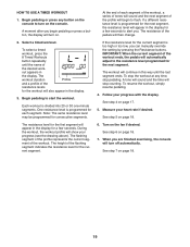
Select a timed workout. out appears in the display for the next segment. One resistance level is programmed for the next segment, the resistance level will appear in the display for the workout will automatically adjust to the resistance level programmed for a few seconds to flash. The flashing segment of the profile represents the current segment of the desired work- See step 4 on the fan if desired. Turn on page 17. 5. A moment after you begin to alert you. Note: The same resistance level may be programmed for each segment of the workout, a series of tones ...
Select a timed workout. out appears in the display for the next segment. One resistance level is programmed for the next segment, the resistance level will appear in the display for the workout will automatically adjust to the resistance level programmed for a few seconds to flash. The flashing segment of the profile represents the current segment of the desired work- See step 4 on the fan if desired. Turn on page 17. 5. A moment after you begin to alert you. Note: The same resistance level may be programmed for each segment of the workout, a series of tones ...
English Manual
Page 20
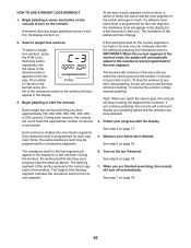
A moment after you reach the calorie goal, the console will stop the workout at any button on the console to turn on page 18. To select a weight loss workout, press the 8 Wt. If the resistance level for a few seconds to display your progress (see the drawing above). The workout will continue to alert you have pedaled. 4. however, if you continue pedaling, the console will continue in this way until the name of the workout. Follow your heart rate if desired. The resistance level for the first segment will appear in the display for the current segment is too ...
A moment after you reach the calorie goal, the console will stop the workout at any button on the console to turn on page 18. To select a weight loss workout, press the 8 Wt. If the resistance level for a few seconds to display your progress (see the drawing above). The workout will continue to alert you have pedaled. 4. however, if you continue pedaling, the console will continue in this way until the name of the workout. Follow your heart rate if desired. The resistance level for the first segment will appear in the display for the current segment is too ...