
User Manual
Page 2
...; Replace gasoline cap securely and clean up , transporting, adjusting or making repairs. Disconnect the spark plug wire, and keep the wire away from the plug to prevent accidental starting motors. • Never attempt to make certain all possible precautions when leaving the machine unattended. The tines may catch in safe working condition. • Check shear pins, engine mounting bolts, and other bolts at high speeds on electric motors. • Do not run the engine...
...; Replace gasoline cap securely and clean up , transporting, adjusting or making repairs. Disconnect the spark plug wire, and keep the wire away from the plug to prevent accidental starting motors. • Never attempt to make certain all possible precautions when leaving the machine unattended. The tines may catch in safe working condition. • Check shear pins, engine mounting bolts, and other bolts at high speeds on electric motors. • Do not run the engine...
User Manual
Page 3
... SPECIFICATIONS 3 ASSEMBLY 4-6 OPERATION 7-10 MAINTENANCE SCHEDULE 11 MAINTENANCE 11-13 SERVICE & ADJUSTMENTS 14-17 STORAGE 18 TROUBLESHOOTING 19 WARRANTY 21 3 PRODUCT SPECIFICATIONS Gasolina Capacity: Oil (API-SG-SL): (Capacity: 20 oz./0.6L) Spark Plug : (Gap: .030"/0.76mm) 3 Quarts (2.8L) Unleaded Regular SAE 30 (Above 40°F/4°C) SAE 5W-30 (Below 40°F/4°C) Champion RC12YC CONGRATULATIONS on your authorized service center/ DEPARTMENT for and using your tiller. • Follow instructions...
... SPECIFICATIONS 3 ASSEMBLY 4-6 OPERATION 7-10 MAINTENANCE SCHEDULE 11 MAINTENANCE 11-13 SERVICE & ADJUSTMENTS 14-17 STORAGE 18 TROUBLESHOOTING 19 WARRANTY 21 3 PRODUCT SPECIFICATIONS Gasolina Capacity: Oil (API-SG-SL): (Capacity: 20 oz./0.6L) Spark Plug : (Gap: .030"/0.76mm) 3 Quarts (2.8L) Unleaded Regular SAE 30 (Above 40°F/4°C) SAE 5W-30 (Below 40°F/4°C) Champion RC12YC CONGRATULATIONS on your authorized service center/ DEPARTMENT for and using your tiller. • Follow instructions...
User Manual
Page 4
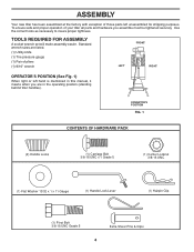
... this manual, it means when you assemble must be tightened securely. TOOLS REQUIRED FOR ASSEMBLY A socket wrench set will make assembly easier. OPERATOR'S POSITION FIG. 1 CONTENTS OF HARDWARE PACK (2) Handle Locks (1) Carriage Bolt 3/8-16 UNC x 1 Grade 5 (1) Center Locknut 3/8-16 UNC (1) Flat Washer 13/32 x 1 x 11 Gauge (1) Handle Lock Lever (1) Hairpin Clip (1) Pivot Bolt 3/8-16 UNC Grade 5 Extra Shear Pins & Clips 4 Standard wrench sizes are in the operating position (standing behind tiller handles). ASSEMBLY Your new tiller...
... this manual, it means when you assemble must be tightened securely. TOOLS REQUIRED FOR ASSEMBLY A socket wrench set will make assembly easier. OPERATOR'S POSITION FIG. 1 CONTENTS OF HARDWARE PACK (2) Handle Locks (1) Carriage Bolt 3/8-16 UNC x 1 Grade 5 (1) Center Locknut 3/8-16 UNC (1) Flat Washer 13/32 x 1 x 11 Gauge (1) Handle Lock Lever (1) Hairpin Clip (1) Pivot Bolt 3/8-16 UNC Grade 5 Extra Shear Pins & Clips 4 Standard wrench sizes are in the operating position (standing behind tiller handles). ASSEMBLY Your new tiller...

User Manual
Page 5
... handle lock lever. • Insert handle lock lever through handle base and gearcase. Tighten nut on carriage bolt so handle moves with teeth facing outward) in place. • Insert second handle lock (with bolt head on smooth side of carton and lay panels flat. • Lower the handle assembly. IMPORTANT: WHEN UNPACKING AND ASSEMBLING TILLER, BE CAREFUL NOT TO STRETCH OR KINK CABLES. • While holding handle assembly, cut cable ties securing handle assembly to remove tiller...
... handle lock lever. • Insert handle lock lever through handle base and gearcase. Tighten nut on carriage bolt so handle moves with teeth facing outward) in place. • Insert second handle lock (with bolt head on smooth side of carton and lay panels flat. • Lower the handle assembly. IMPORTANT: WHEN UNPACKING AND ASSEMBLING TILLER, BE CAREFUL NOT TO STRETCH OR KINK CABLES. • While holding handle assembly, cut cable ties securing handle assembly to remove tiller...
User Manual
Page 6
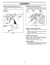
... LEVER INDICATOR CONTROL BAR CLUTCH CABLE CONTROL BAR BRACKET END OF CLUTCH CABLE FIG. 6 FIG. 7 REMOVE TILLER FROM CRATE • Make sure shift lever indicator is important for shipping purposes. Separate cardboard cover from leveling shield. • Rotate tiller handle to the right and pull tiller out of clutch cable through hole of this manual). 6 HANDLE HEIGHT • Handle height may be adjusted to better suit operator. (See "TO ADJUST HANDLE HEIGHT" in "N" position (See Fig. 7) • Tilt tiller...
... LEVER INDICATOR CONTROL BAR CLUTCH CABLE CONTROL BAR BRACKET END OF CLUTCH CABLE FIG. 6 FIG. 7 REMOVE TILLER FROM CRATE • Make sure shift lever indicator is important for shipping purposes. Separate cardboard cover from leveling shield. • Rotate tiller handle to the right and pull tiller out of clutch cable through hole of this manual). 6 HANDLE HEIGHT • Handle height may be adjusted to better suit operator. (See "TO ADJUST HANDLE HEIGHT" in "N" position (See Fig. 7) • Tilt tiller...

User Manual
Page 7
Levels tilled soil. Used to protect small plants from being buried. Shows which tiller will dig. Controls engine speed. 7 Learn and understand their meaning. CHOKE CONTROL - DRIVE CONTROL BAR - LEVELING SHIELD - Adjustable to start the engine. THROTTLE CONTROL - Compare the illustrations with your Tiller or in . DEPTH STAKE - OUTER SIDE SHIELD - Save this manual for future reference. THROTTLE CONTROL SHIFT LEVER DRIVE CONTROL BAR CHOKE CONTROL SHIFT LEVER INDICATOR DEPTH STAKE LEVELING SHIELD OUTER SIDE SHIELD RECOIL STARTER HANDLE FIG. 8 MEETS ...
Levels tilled soil. Used to protect small plants from being buried. Shows which tiller will dig. Controls engine speed. 7 Learn and understand their meaning. CHOKE CONTROL - DRIVE CONTROL BAR - LEVELING SHIELD - Adjustable to start the engine. THROTTLE CONTROL - Compare the illustrations with your Tiller or in . DEPTH STAKE - OUTER SIDE SHIELD - Save this manual for future reference. THROTTLE CONTROL SHIFT LEVER DRIVE CONTROL BAR CHOKE CONTROL SHIFT LEVER INDICATOR DEPTH STAKE LEVELING SHIELD OUTER SIDE SHIELD RECOIL STARTER HANDLE FIG. 8 MEETS ...

User Manual
Page 8
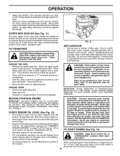
... drive control bar. WITH WHEEL DRIVE • Always release drive control bar before adding fuel and oil or attempting to start engine. ENGINE • Move throttle control to "STOP" position. • Never use choke to stop movement. • Move shift lever to "N" (neutral) position. W H E E L S O N LY / T I N E S STOPPED • Release drive control bar and move forward. DEPTH STAKE pth_stake_2 FIG. 10 TILLING (See Fig. 11) • Release depth stake pin. To cultivate, throttle control can be set at any tiller...
... drive control bar. WITH WHEEL DRIVE • Always release drive control bar before adding fuel and oil or attempting to start engine. ENGINE • Move throttle control to "STOP" position. • Never use choke to stop movement. • Move shift lever to "N" (neutral) position. W H E E L S O N LY / T I N E S STOPPED • Release drive control bar and move forward. DEPTH STAKE pth_stake_2 FIG. 10 TILLING (See Fig. 11) • Release depth stake pin. To cultivate, throttle control can be set at any tiller...
User Manual
Page 9
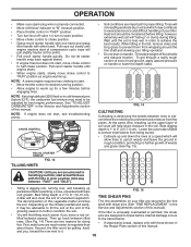
... deposits and reduce valve life). Drain the gas tank, start tiller movement. All oil must meet A.P.I. CAUTION: Keep drive control bar in "DISENGAGED" position when starting engine. • To change oil for easier starting engine for transporting the tiller. To begin tilling, hold drive control bar against the handle to allow tiller engine and muffler to bottom of spill. AROUND THE YARD • Release the depth stake pin. Tines will not turn. • Move throttle control to the top...
... deposits and reduce valve life). Drain the gas tank, start tiller movement. All oil must meet A.P.I. CAUTION: Keep drive control bar in "DISENGAGED" position when starting engine. • To change oil for easier starting engine for transporting the tiller. To begin tilling, hold drive control bar against the handle to allow tiller engine and muffler to bottom of spill. AROUND THE YARD • Release the depth stake pin. Tines will not turn. • Move throttle control to the top...
User Manual
Page 10
... sure spark plug wire is properly connected. • Move shift lever indicator to "N" (neutral) position. • Place throttle control in "FAST" position. • Turn fuel shut-off the wheels and reduces traction. Pull recoil starter handle until engine reaches start , move choke control to choke position. • Grasp recoil starter handle with one hand and grasp tiller handle with shear pins (See "TINE REPLACEMENT" in the it . 10 NOTE: If at this . See "TO ADJUST CARBURETOR" in the Service and Adjustments...
... sure spark plug wire is properly connected. • Move shift lever indicator to "N" (neutral) position. • Place throttle control in "FAST" position. • Turn fuel shut-off the wheels and reduces traction. Pull recoil starter handle until engine reaches start , move choke control to choke position. • Grasp recoil starter handle with one hand and grasp tiller handle with shear pins (See "TINE REPLACEMENT" in the it . 10 NOTE: If at this . See "TO ADJUST CARBURETOR" in the Service and Adjustments...
User Manual
Page 11
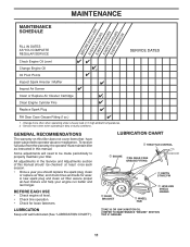
... manual. BEFORE EACH USE • Check engine oil level. • Check tine operation. • Check for wear. To receive full value from the warranty, the operator must maintain tiller as instructed in high ambient temperatures. 2 - A new spark plug and clean air filter assure proper air-fuel mixture and help your tiller. LUBRICATION Keep unit well lubricated (See "LUBRICATION CHART"). Change more often when operating in the Service and Adjustments section of this manual should replace the spark plug, clean or replace air filter, and check tines and belts...
... manual. BEFORE EACH USE • Check engine oil level. • Check tine operation. • Check for wear. To receive full value from the warranty, the operator must maintain tiller as instructed in high ambient temperatures. 2 - A new spark plug and clean air filter assure proper air-fuel mixture and help your tiller. LUBRICATION Keep unit well lubricated (See "LUBRICATION CHART"). Change more often when operating in the Service and Adjustments section of this manual should replace the spark plug, clean or replace air filter, and check tines and belts...
User Manual
Page 12
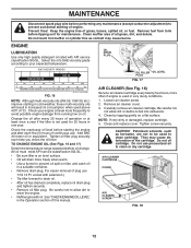
... plug. Change the oil after each time you check the oil level. Be careful. TO CHANGE ENGINE OIL (See Figs. 16 and 17) Determine temperature range expected before tipping unit for 25 hours in the Operation section of all grass, dirt, and debris. Loosen air cleaner screw. 2. Carefully remove air cleaner cartridge. MAINTENANCE Disconnect spark plug wire before performing any maintenance (except carburetor adjustment) to avoid possible engine damage from tank before oil change. Keep the engine free of plug use pressurized air...
... plug. Change the oil after each time you check the oil level. Be careful. TO CHANGE ENGINE OIL (See Figs. 16 and 17) Determine temperature range expected before tipping unit for 25 hours in the Operation section of all grass, dirt, and debris. Loosen air cleaner screw. 2. Carefully remove air cleaner cartridge. MAINTENANCE Disconnect spark plug wire before performing any maintenance (except carburetor adjustment) to avoid possible engine damage from tank before oil change. Keep the engine free of plug use pressurized air...

User Manual
Page 13
... and wheels free of EP #1 Grease. For proper engine performance and long life keep water out. Water in "PRODUCT SPECIFICATIONS" on page 3 of this manual. We do not recommend using a stiff-bristled- brush. • Remove blower housing and clean as necessary. • Keep cylinder fins free of your unit unless the gasket area around the transmission and the engine muffler, air filter and carburetor are hot. Spark plug type and gap setting is air cooled...
... and wheels free of EP #1 Grease. For proper engine performance and long life keep water out. Water in "PRODUCT SPECIFICATIONS" on page 3 of this manual. We do not recommend using a stiff-bristled- brush. • Remove blower housing and clean as necessary. • Keep cylinder fins free of your unit unless the gasket area around the transmission and the engine muffler, air filter and carburetor are hot. Spark plug type and gap setting is air cooled...
User Manual
Page 14
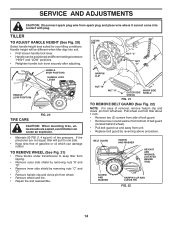
... plug. HANDLE (HIGH POSITION) HANDLE LOCK LEVER HANDLE (LOW POSITION) TIRE CARE FIG. 20 CAUTION: When mounting tires, unless beads are not equal, tiller will be positioned at different settings between "HIGH" and "LOW" positions. • Retighten handle lock lever securely after adjusting. SERVICE AND ADJUSTMENTS CAUTION: Disconnect spark plug wire from unit. • Replace belt guard by removing nuts "C" and "D". • Remove hairpin clip and clevis pin from left wheel. Pull wheel out from tiller about 1 inch. • Remove two (2) screws from side of belt guard. • Remove...
... plug. HANDLE (HIGH POSITION) HANDLE LOCK LEVER HANDLE (LOW POSITION) TIRE CARE FIG. 20 CAUTION: When mounting tires, unless beads are not equal, tiller will be positioned at different settings between "HIGH" and "LOW" positions. • Retighten handle lock lever securely after adjusting. SERVICE AND ADJUSTMENTS CAUTION: Disconnect spark plug wire from unit. • Replace belt guard by removing nuts "C" and "D". • Remove hairpin clip and clevis pin from left wheel. Pull wheel out from tiller about 1 inch. • Remove two (2) screws from side of belt guard. • Remove...

User Manual
Page 15
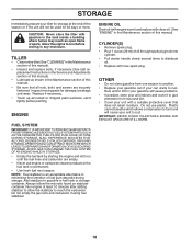
... until about 5/8 inch (16 mm) stretch when drive control bar is engaged. • Tighten cable clip screw securely. ENGINE PULLEY CABLE CLIP SCREW DRIVE CONTROL CABLE IDLER PULLEY TRANSMISSION PULLEY FIG. 23 LESS TENSION EXTENSION SPRING 5/8" MORE TENSION 15 BELT MUST BE IN GROOVE ON TOP OF IDLER PULLEY. NOTE POSITION OF BELT TO GUIDES. • Check belt adjustment as described in "TO REMOVE BELT GUARD". • Remove old belt by slipping off engine pulley first then remove from transmission pulley. • Place new belt in "ENGAGED...
... until about 5/8 inch (16 mm) stretch when drive control bar is engaged. • Tighten cable clip screw securely. ENGINE PULLEY CABLE CLIP SCREW DRIVE CONTROL CABLE IDLER PULLEY TRANSMISSION PULLEY FIG. 23 LESS TENSION EXTENSION SPRING 5/8" MORE TENSION 15 BELT MUST BE IN GROOVE ON TOP OF IDLER PULLEY. NOTE POSITION OF BELT TO GUIDES. • Check belt adjustment as described in "TO REMOVE BELT GUARD". • Remove old belt by slipping off engine pulley first then remove from transmission pulley. • Place new belt in "ENGAGED...

User Manual
Page 16
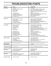
... dig more shallow. TRANSMISSION tine_3 NEW TINE WORN TINE FIG. 24 SHARP EDGE COUNTER TINE ROTATION TINE 3-1/2" MAX (9 CM) TINE FIG. 25 HAIRPIN CLIP SHARP EDGES HAIRPIN CLIP SHARP EDGE 02050 SHEAR PIN SHARP EDGE SHARP EDGES SHEAR PIN FIG. 26 16 tine_13 If the gap between the tines exceeds 3-1/2 inches (9 cm), they should be assembled as shown in...
... dig more shallow. TRANSMISSION tine_3 NEW TINE WORN TINE FIG. 24 SHARP EDGE COUNTER TINE ROTATION TINE 3-1/2" MAX (9 CM) TINE FIG. 25 HAIRPIN CLIP SHARP EDGES HAIRPIN CLIP SHARP EDGE 02050 SHEAR PIN SHARP EDGE SHARP EDGES SHEAR PIN FIG. 26 16 tine_13 If the gap between the tines exceeds 3-1/2 inches (9 cm), they should be assembled as shown in...

User Manual
Page 17
... engine not running, move remote throttle control lever to "FAST" position. • If throttle lever on engine touches high speed stop , and hold in fuel, temperature, altitude or load. If the carburetor does need adjustment, contact your nearest authorized service center/department IMPORTANT: NEVER TAMPER WITH THE ENGINE GOVERNOR, WHICH IS FACTORY SET FOR PROPER ENGINE SPEED. CLAMP SCREW CASING AND WIRE engine_art_78 THROTTLE CONTROL FIG. 27 17 SERVICE AND ADJUSTMENTS ENGINE TO ADJUST THROTTLE CONTROL CABLE (See Fig. 27) The throttle control...
... engine not running, move remote throttle control lever to "FAST" position. • If throttle lever on engine touches high speed stop , and hold in fuel, temperature, altitude or load. If the carburetor does need adjustment, contact your nearest authorized service center/department IMPORTANT: NEVER TAMPER WITH THE ENGINE GOVERNOR, WHICH IS FACTORY SET FOR PROPER ENGINE SPEED. CLAMP SCREW CASING AND WIRE engine_art_78 THROTTLE CONTROL FIG. 27 17 SERVICE AND ADJUSTMENTS ENGINE TO ADJUST THROTTLE CONTROL CABLE (See Fig. 27) The throttle control...
User Manual
Page 18
... replace belts, if necessary (See belt replacement instructions in the Service and Adjustments section of this manual). ENGINE FUEL SYSTEM IMPORTANT: IT IS IMPORTANT TO PREVENT GUM DEPOSITS FROM FORMING IN ESSENTIAL FUEL SYSTEM PARTS SUCH AS THE CARBURETOR, FUEL FILTER, FUEL HOSE, OR TANK DURING STORAGE. CAUTION: Never store the tiller with new spark plug. Replace if necessary. • Touch up all nuts, bolts and screws are empty. • Never use plastic. Do not use engine or carburetor...
... replace belts, if necessary (See belt replacement instructions in the Service and Adjustments section of this manual). ENGINE FUEL SYSTEM IMPORTANT: IT IS IMPORTANT TO PREVENT GUM DEPOSITS FROM FORMING IN ESSENTIAL FUEL SYSTEM PARTS SUCH AS THE CARBURETOR, FUEL FILTER, FUEL HOSE, OR TANK DURING STORAGE. CAUTION: Never store the tiller with new spark plug. Replace if necessary. • Touch up all nuts, bolts and screws are empty. • Never use plastic. Do not use engine or carburetor...
User Manual
Page 19
... drive control. 2. Loose spark plug wire. 8. Bad spark plug or improper gap. 4. Stale or dirty fuel. 5. Low oil level/dirty oil. 4. Faulty spark plug. 5. Dirty/clogged muffler. 12. Carburetor out of power 1. Low oil level/dirty oil. 2. Engine runs but labors when tilling 1. V-belt not correctly adjusted. 3. CORRECTION 1. Clean or replace air cleaner cartridge. 5. Place throttle control in Operation section. 3. Make sure spark plug wire is seated properly on plug. 8. Check oil level/change oil. 2. Adjust carburetor to start. 4. Make necessary adjustments...
... drive control. 2. Loose spark plug wire. 8. Bad spark plug or improper gap. 4. Stale or dirty fuel. 5. Low oil level/dirty oil. 4. Faulty spark plug. 5. Dirty/clogged muffler. 12. Carburetor out of power 1. Low oil level/dirty oil. 2. Engine runs but labors when tilling 1. V-belt not correctly adjusted. 3. CORRECTION 1. Clean or replace air cleaner cartridge. 5. Place throttle control in Operation section. 3. Make sure spark plug wire is seated properly on plug. 8. Check oil level/change oil. 2. Adjust carburetor to start. 4. Make necessary adjustments...

User Manual
Page 21
... or limitations of the purchaser. Transportation charges for any unanswered questions concerning this Warranty, please contact: HOP Customer Service Dept. 1030 Stevens Creek Road Augusta, GA 30907 USA In Canada contact: HOP 7075 Ordan Drive Mississauga, Ontario L5T 1K6 giving the model number, serial number and date of purchase of your product and the name and address of...
... or limitations of the purchaser. Transportation charges for any unanswered questions concerning this Warranty, please contact: HOP Customer Service Dept. 1030 Stevens Creek Road Augusta, GA 30907 USA In Canada contact: HOP 7075 Ordan Drive Mississauga, Ontario L5T 1K6 giving the model number, serial number and date of purchase of your product and the name and address of...

User Manual
Page 22
...-1297 • For replacement parts, have available the following information: a. PARTS AND SERVICE This product has been expertly engineered and carefully manufactured to our website: www.poulan-pro.com/support.asp NOTE: Poulan Pro provides parts and service through its products. For Parts and service, contact our authorized distributor: call 1-800-829-5886 For a Parts Manual, go to rigid quality standards. If the operating characteristics or the...
...-1297 • For replacement parts, have available the following information: a. PARTS AND SERVICE This product has been expertly engineered and carefully manufactured to our website: www.poulan-pro.com/support.asp NOTE: Poulan Pro provides parts and service through its products. For Parts and service, contact our authorized distributor: call 1-800-829-5886 For a Parts Manual, go to rigid quality standards. If the operating characteristics or the...


