
User Manual
Page 2
... avoid slipping or falling, especially when operating the snow thrower in the manual(s) before starting when setting up spilled fuel. (h) If fuel is spilled on surfaces above ground level such as specified by manufacturer). 8. YOUR SAFETY IS INVOLVED. Do not use a nozzle lock-open device. (g) Replace gasoline cap securely and wipe up , transporting, adjusting or making any adjustments while the engine (motor) is not possible, then refuel...
... avoid slipping or falling, especially when operating the snow thrower in the manual(s) before starting when setting up spilled fuel. (h) If fuel is spilled on surfaces above ground level such as specified by manufacturer). 8. YOUR SAFETY IS INVOLVED. Do not use a nozzle lock-open device. (g) Replace gasoline cap securely and wipe up , transporting, adjusting or making any adjustments while the engine (motor) is not possible, then refuel...
User Manual
Page 3
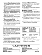
... is to service or repair this manual. SERIAL NUMBER DATE OF PURCHASE THE MODEL AND SERIAL NUMBERS WILL BE FOUND ON A DECAL ATTACHED TO THE REAR OF THE SNOW THROWER HOUSING. Maintenance and Storage 1. TABLE OF CONTENTS SAFETY RULES 2-3 PRODUCT SPECIFICATIONS 3 CUSTOMER RESPONSIBILITIES 3 ASSEMBLY / PRE-OPERATION 4-7 OPERATION 8-13 MAINTENANCE SCHEDULE 14 MAINTENANCE 14-15 SERVICE AND ADJUSTMENTS 16-18 STORAGE 19 TROUBLESHOOTING 20 REPAIR PARTS 22-42 WARRANTY BACK COVER 3 Do not run . 16. Never operate the machine...
... is to service or repair this manual. SERIAL NUMBER DATE OF PURCHASE THE MODEL AND SERIAL NUMBERS WILL BE FOUND ON A DECAL ATTACHED TO THE REAR OF THE SNOW THROWER HOUSING. Maintenance and Storage 1. TABLE OF CONTENTS SAFETY RULES 2-3 PRODUCT SPECIFICATIONS 3 CUSTOMER RESPONSIBILITIES 3 ASSEMBLY / PRE-OPERATION 4-7 OPERATION 8-13 MAINTENANCE SCHEDULE 14 MAINTENANCE 14-15 SERVICE AND ADJUSTMENTS 16-18 STORAGE 19 TROUBLESHOOTING 20 REPAIR PARTS 22-42 WARRANTY BACK COVER 3 Do not run . 16. Never operate the machine...

User Manual
Page 4
... assemble must be tightened securely. Use the correct tools as nuts, washers, bolts, etc., necessary to the pallet. 6. Remove all parts and hardware you attempt to lower handle. 5. PARTS PACKED SEPARATELY IN CARTON (1) MULTIWRENCH (180684) (1) POWER CORD (198563) SAFTEY IGNITION KEY(S) (193071) (1) AUGER CONTROL ROD (1) DISCHARGE CHUTE EXTRA SHEAR BOLTS AND NUTS (2) SHOULDER BOLT 1/4-20 x 1-3/4 (192090) (2) LOCKNUTS 1/4-20 (73800400) ROTATOR HEAD MOUNTING (3) RETAINER SPRINGS (169675) (1) WASHER 3/8 (19131316) (1) LOCKNUT 3/8 (73800600) CHUTE DEFLECTOR REMOTE CONTROL...
... assemble must be tightened securely. Use the correct tools as nuts, washers, bolts, etc., necessary to the pallet. 6. Remove all parts and hardware you attempt to lower handle. 5. PARTS PACKED SEPARATELY IN CARTON (1) MULTIWRENCH (180684) (1) POWER CORD (198563) SAFTEY IGNITION KEY(S) (193071) (1) AUGER CONTROL ROD (1) DISCHARGE CHUTE EXTRA SHEAR BOLTS AND NUTS (2) SHOULDER BOLT 1/4-20 x 1-3/4 (192090) (2) LOCKNUTS 1/4-20 (73800400) ROTATOR HEAD MOUNTING (3) RETAINER SPRINGS (169675) (1) WASHER 3/8 (19131316) (1) LOCKNUT 3/8 (73800600) CHUTE DEFLECTOR REMOTE CONTROL...

User Manual
Page 5
... of the chute rotator head to snow thrower and making adjustments to the skid plates. Use to secure upper handle to lower handle. 2. INSTALL SPEED CONTROL ROD (See Figs. 1 and 2) 1. PLASTIC TIE TRACTION DRIVE CONTROL ROD VINYL SLEEVE HANDLE KNOB LOWER HANDLE FIG. 1 SPEED CONTROL ROD RETAINER SPRING SPEED CONTROL BRACKET SPEED CONTROL LEVER FIG. 2 5 FIG. 3 TRACTION DRIVE CONTROL LEVER RETAINER SPRING DRIVE CONTROL BRACKET FIG. 4 TRACTION DRIVE CONTROL ROD Insert rod into hole in drive control bracket. Secure with retainer spring. UNFOLD UPPER HANDLE 1. Remove plastic...
... of the chute rotator head to snow thrower and making adjustments to the skid plates. Use to secure upper handle to lower handle. 2. INSTALL SPEED CONTROL ROD (See Figs. 1 and 2) 1. PLASTIC TIE TRACTION DRIVE CONTROL ROD VINYL SLEEVE HANDLE KNOB LOWER HANDLE FIG. 1 SPEED CONTROL ROD RETAINER SPRING SPEED CONTROL BRACKET SPEED CONTROL LEVER FIG. 2 5 FIG. 3 TRACTION DRIVE CONTROL LEVER RETAINER SPRING DRIVE CONTROL BRACKET FIG. 4 TRACTION DRIVE CONTROL ROD Insert rod into hole in drive control bracket. Secure with retainer spring. UNFOLD UPPER HANDLE 1. Remove plastic...

User Manual
Page 6
... spring. CONTROL ARM AUGER CONTROL ROD VINYL SLEEVE CHUTE ROTATER HEAD 3/8 LOCKNUT 3/8 WASHER LOOP OPENING UP FIG. 5 AUGER CONTROL ROD AUGER CONTROL RETAINER LEVER SPRING CHUTE BRACKET ALIGN BEFORE TIGHTENING LOCKNUT FIG. 7 PIN THREADED STUD ROTATER HEAD MOUNTING BRACKET AUGER CONTROL BRACKET FIG. 6 6 With top end of rod positioned under right side of control panel, push down on underside of snow thrower. 2. Secure with holes in auger control bracket. Position chute rotater head over chute bracket. ASSEMBLY / PRE-OPERATION INSTALL AUGER CONTROL...
... spring. CONTROL ARM AUGER CONTROL ROD VINYL SLEEVE CHUTE ROTATER HEAD 3/8 LOCKNUT 3/8 WASHER LOOP OPENING UP FIG. 5 AUGER CONTROL ROD AUGER CONTROL RETAINER LEVER SPRING CHUTE BRACKET ALIGN BEFORE TIGHTENING LOCKNUT FIG. 7 PIN THREADED STUD ROTATER HEAD MOUNTING BRACKET AUGER CONTROL BRACKET FIG. 6 6 With top end of rod positioned under right side of control panel, push down on underside of snow thrower. 2. Secure with holes in auger control bracket. Position chute rotater head over chute bracket. ASSEMBLY / PRE-OPERATION INSTALL AUGER CONTROL...

User Manual
Page 7
... chute rotater head and into hole in chute deflector as shown. 1/4-20 SHOULDER BOLT 1/4-20 LOCKNUT SPRING CHUTE DEFLECTOR HOOK BETWEEN HEX NUTS ON CHUTE ROTATER HEAD 5/16-18 CARRIAGE BOLT CHECK TIRE PRESSURE The tires on shoulder bolt. 3. Install remote cable bracket to discharge chute with 1/4-20 shoulder bolt and 1/4-20 locknut as shown. CABLE EYELET REMOTE CABLE BRACKET 5/16-18 LOCKNUT FIG. 8 CHUTE DEFLECTOR CONTROL LEVER FIG. 9 7 ASSEMBLY / PRE-OPERATION INSTALL CHUTE DEFLECTOR REMOTE CONTROL...
... chute rotater head and into hole in chute deflector as shown. 1/4-20 SHOULDER BOLT 1/4-20 LOCKNUT SPRING CHUTE DEFLECTOR HOOK BETWEEN HEX NUTS ON CHUTE ROTATER HEAD 5/16-18 CARRIAGE BOLT CHECK TIRE PRESSURE The tires on shoulder bolt. 3. Install remote cable bracket to discharge chute with 1/4-20 shoulder bolt and 1/4-20 locknut as shown. CABLE EYELET REMOTE CABLE BRACKET 5/16-18 LOCKNUT FIG. 8 CHUTE DEFLECTOR CONTROL LEVER FIG. 9 7 ASSEMBLY / PRE-OPERATION INSTALL CHUTE DEFLECTOR REMOTE CONTROL...
User Manual
Page 9
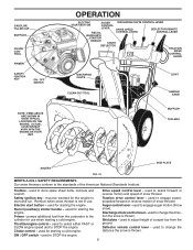
... Our snow throwers conform to the cylinder for use . used for starting a cold engine. used for starting a cold engine. used for the engine to engage auger motion (throw snow). OPERATION ELECTRIC AUGER DISCHARGE CHUTE CONTROL LEVER START BUTTON CONTROL LEVER DRIVE SPEED DEFLECTOR REMOTE RECOIL CONTROL LEVER CONTROL LEVER (AUXILIARY) STARTER HANDLE CHUTE DEFLECTOR TRACTION DRIVE CONTROL LEVER DISCHARGE CHUTE CLEAN-OUT TOOL LIGHT HANDLE KNOB MUFFLER TOOLBOX SKID PLATE AUGERS FIG. 10 MEETS A.N.S.I. Primer - must be inserted for starting the engine...
... Our snow throwers conform to the cylinder for use . used for starting a cold engine. used for starting a cold engine. used for the engine to engage auger motion (throw snow). OPERATION ELECTRIC AUGER DISCHARGE CHUTE CONTROL LEVER START BUTTON CONTROL LEVER DRIVE SPEED DEFLECTOR REMOTE RECOIL CONTROL LEVER CONTROL LEVER (AUXILIARY) STARTER HANDLE CHUTE DEFLECTOR TRACTION DRIVE CONTROL LEVER DISCHARGE CHUTE CLEAN-OUT TOOL LIGHT HANDLE KNOB MUFFLER TOOLBOX SKID PLATE AUGERS FIG. 10 MEETS A.N.S.I. Primer - must be inserted for starting the engine...

User Manual
Page 10
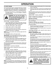
... engine. Remove (do not turn) safety ignition key to prevent unauthorized use to stop throwing snow. The DIRECTION in desired position. Set the deflector low to lower the deflector and decrease the distance. Move lever back to throw snow a short distance; Be sure lever springs back and locks into desired position. AUGER • Release the auger control lever to operate all times including startup. Move ON / OFF switch to disengage. TO USE CHOKE CONTROL...
... engine. Remove (do not turn) safety ignition key to prevent unauthorized use to stop throwing snow. The DIRECTION in desired position. Set the deflector low to lower the deflector and decrease the distance. Move lever back to throw snow a short distance; Be sure lever springs back and locks into desired position. AUGER • Release the auger control lever to operate all times including startup. Move ON / OFF switch to disengage. TO USE CHOKE CONTROL...

User Manual
Page 11
... all controls are for light snow and transporting the snow thrower. This will lock the auger control lever in the engaged position. Disconnect the spark plug wire and keep the wire away from the spark plug to prevent accidental starting. • Release the auger control lever and shut off the engine. • Remove the clean-out tool from it into the clip. • Make sure the discharge chute is recommended that you use a slower speed until...
... all controls are for light snow and transporting the snow thrower. This will lock the auger control lever in the engaged position. Disconnect the spark plug wire and keep the wire away from the spark plug to prevent accidental starting. • Release the auger control lever and shut off the engine. • Remove the clean-out tool from it into the clip. • Make sure the discharge chute is recommended that you use a slower speed until...
User Manual
Page 12
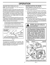
...; To change engine oil, see "TO CHANGE ENGINE OIL" in the Maintenance section of acids during storage. Use fresh, clean, regular unleaded gasoline with oil. 1. Use fresh fuel next season. CHOKE CONTROL ENGINE OIL FILL CAP / DIPSTICK GASOLINE FILLER CAP STARTER BUTTON PRIMER SAFETY IGNITION KEY RECOIL STARTER HANDLE ON / OFF SWITCH NOTE: ALL ITEMS ARE SHOWN IN THEIR TYPICAL LOCATION. HIGH POSITION (LOW GROUND CLEARANCE) HEX NUTS AUGER HOUSING SCRAPER BAR SKID PLATE LOW POSITION (HIGH GROUND CLEARANCE) FIG. 16 SCRAPER BAR (See...
...; To change engine oil, see "TO CHANGE ENGINE OIL" in the Maintenance section of acids during storage. Use fresh, clean, regular unleaded gasoline with oil. 1. Use fresh fuel next season. CHOKE CONTROL ENGINE OIL FILL CAP / DIPSTICK GASOLINE FILLER CAP STARTER BUTTON PRIMER SAFETY IGNITION KEY RECOIL STARTER HANDLE ON / OFF SWITCH NOTE: ALL ITEMS ARE SHOWN IN THEIR TYPICAL LOCATION. HIGH POSITION (LOW GROUND CLEARANCE) HEX NUTS AUGER HOUSING SCRAPER BAR SKID PLATE LOW POSITION (HIGH GROUND CLEARANCE) FIG. 16 SCRAPER BAR (See...
User Manual
Page 13
... steps or use primer when starting . Pull recoil starter handle quickly. DO NOT push the primer. See "TO ADJUST SKID PLATES" in the "OFF" position. This will help dry off the engine. • Clean the entire snow thrower thoroughly after it clicks. OPERATION TO START ENGINE Your snow thrower engine is ready for next use. ELECTRIC STARTER 1. COLD START - Insert safety ignition key (tied to remove snow is the early morning. Push the primer four (4) times if the...
... steps or use primer when starting . Pull recoil starter handle quickly. DO NOT push the primer. See "TO ADJUST SKID PLATES" in the "OFF" position. This will help dry off the engine. • Clean the entire snow thrower thoroughly after it clicks. OPERATION TO START ENGINE Your snow thrower engine is ready for next use. ELECTRIC STARTER 1. COLD START - Insert safety ignition key (tied to remove snow is the early morning. Push the primer four (4) times if the...
User Manual
Page 14
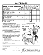
...; Engine oil SNOW THROWER Always observe the safety rules when performing any of the adjustments described in this manual. • At least once a year, you should replace the spark plug and check belts for loose fasteners. 3. Tire sealant also prevents tire dry rot and corrosion. 14 Check engine oil level. 2. A new spark plug will need to be made periodically to be purchased from the warranty, operator must maintain snow thrower as instructed in the Service...
...; Engine oil SNOW THROWER Always observe the safety rules when performing any of the adjustments described in this manual. • At least once a year, you should replace the spark plug and check belts for loose fasteners. 3. Tire sealant also prevents tire dry rot and corrosion. 14 Check engine oil level. 2. A new spark plug will need to be made periodically to be purchased from the warranty, operator must maintain snow thrower as instructed in the Service...

User Manual
Page 15
... manual). 7. Spark plug type and gap setting are covered to the oil drain plug and placement of your snow thrower unless the electrical system, muffler and carburetor are shown in the "PRODUCT SPECIFICATIONS" section of operation or at the factory. Change the oil after each time you check the oil level. Remove safety ignition key and disconnect spark plug wire from your nearest dealer. Install left wheel removed, will drain more frequently to your snow thrower after every 25 hours of this manual). Remove oil fill cap/dipstick. SPARK PLUG Replace spark...
... manual). 7. Spark plug type and gap setting are covered to the oil drain plug and placement of your snow thrower unless the electrical system, muffler and carburetor are shown in the "PRODUCT SPECIFICATIONS" section of operation or at the factory. Change the oil after each time you check the oil level. Remove safety ignition key and disconnect spark plug wire from your nearest dealer. Install left wheel removed, will drain more frequently to your snow thrower after every 25 hours of this manual). Remove oil fill cap/dipstick. SPARK PLUG Replace spark...
User Manual
Page 16
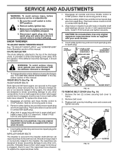
... throttle control to see "TO CONTROL SNOW DISCHARGE" in the Operation section of the bolts have sheared. Remove the two (2) screws securing belt cover to spark plug. If impeller does not turn when auger control lever is discharged, see if the capscrews have sheared. Remove safety ignition key and disconnect spark plug wire from spark plug and place wire where it should be replaced. 1. Disengage all moving parts have completely stopped. 4. IMPELLER SHEAR BOLTS The impeller is engaged, check to STOP position...
... throttle control to see "TO CONTROL SNOW DISCHARGE" in the Operation section of the bolts have sheared. Remove the two (2) screws securing belt cover to spark plug. If impeller does not turn when auger control lever is discharged, see if the capscrews have sheared. Remove safety ignition key and disconnect spark plug wire from spark plug and place wire where it should be replaced. 1. Disengage all moving parts have completely stopped. 4. IMPELLER SHEAR BOLTS The impeller is engaged, check to STOP position...

User Manual
Page 17
... BRACKET AUGER PULLEY AUGER HOUSING BOLTS 6. WARNING: Belt replacement requires separation of belts. See "TO REMOVE BELT COVER" in the Assembly / Pre-Operation section of pulley. 13. REMOVE ENGINE PULLEY - If auger belt has become dislodged from snow thrower. 3. REMOVE HAIRPIN FROM CLUTCH ROD and remove clutch rod from your snow thrower are of auger pulley only. 12. With tension relieved on your nearest Sears service centre/department. INSTALL ENGINE PULLEY - The V-belts on idler, install new traction drive belt around and inside belt keeper. 16. Using...
... BRACKET AUGER PULLEY AUGER HOUSING BOLTS 6. WARNING: Belt replacement requires separation of belts. See "TO REMOVE BELT COVER" in the Assembly / Pre-Operation section of pulley. 13. REMOVE ENGINE PULLEY - If auger belt has become dislodged from snow thrower. 3. REMOVE HAIRPIN FROM CLUTCH ROD and remove clutch rod from your snow thrower are of auger pulley only. 12. With tension relieved on your nearest Sears service centre/department. INSTALL ENGINE PULLEY - The V-belts on idler, install new traction drive belt around and inside belt keeper. 16. Using...
User Manual
Page 18
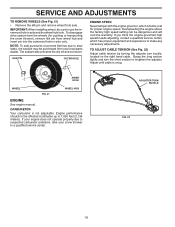
... section tightly and turn buckle, located on the right hand cable. NOTE: To seal punctures or prevent flat tires due to slow leaks, tire sealant may be dangerous and will void the warranty. If you think the engine-governed high speed needs adjusting, contact a qualified service center, which is factory set for pushing or transporting the snow thrower), remove klik pin from wheel hub and insert...
... section tightly and turn buckle, located on the right hand cable. NOTE: To seal punctures or prevent flat tires due to slow leaks, tire sealant may be dangerous and will void the warranty. If you think the engine-governed high speed needs adjusting, contact a qualified service center, which is factory set for pushing or transporting the snow thrower), remove klik pin from wheel hub and insert...
User Manual
Page 19
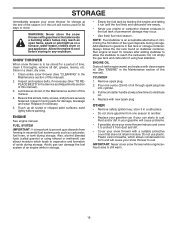
Allow the engine to cool before painting. Replace if necessary. 5. Touch up all nuts, bolts, screws, and pins are empty. • Never use plastic. Acidic gas can if your snow thrower with clean engine oil. (See "ENGINE" in the Maintenance section of time, clean it from one ounce (29 ml) of this manual). 3. Always follow the mix ratio found on a furnace, water heater, clothes dryer or gas appliance. Remove spark plug. 2. Plastic cannot breathe, which...
Allow the engine to cool before painting. Replace if necessary. 5. Touch up all nuts, bolts, screws, and pins are empty. • Never use plastic. Acidic gas can if your snow thrower with clean engine oil. (See "ENGINE" in the Maintenance section of time, clean it from one ounce (29 ml) of this manual). 3. Always follow the mix ratio found on a furnace, water heater, clothes dryer or gas appliance. Remove spark plug. 2. Plastic cannot breathe, which...
User Manual
Page 20
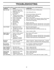
.... Recoil starter is in need of pulley. 2. Drive belt is in OFF position. 6. Clean snow chute. 4. Throttle in fuel. 5. Primer not depressed. 7. Move throttle to FAST position (or ON/OFF switch to OPEN position. 2. Prime as instructed in the Operation section of drive speed 3. Loss of this manual. Dirty or clogged muffler. 1. Engine idles or runs roughly 1. Clean fuel line. 3. Loose parts or damaged augers or impeller. 1. Drive belt is worn. 3. Remove debris or foreign object from augers / impeller. 20 Turn fuel shut-off valve (if so...
.... Recoil starter is in need of pulley. 2. Drive belt is in OFF position. 6. Clean snow chute. 4. Throttle in fuel. 5. Primer not depressed. 7. Move throttle to FAST position (or ON/OFF switch to OPEN position. 2. Prime as instructed in the Operation section of drive speed 3. Loss of this manual. Dirty or clogged muffler. 1. Engine idles or runs roughly 1. Clean fuel line. 3. Loose parts or damaged augers or impeller. 1. Drive belt is worn. 3. Remove debris or foreign object from augers / impeller. 20 Turn fuel shut-off valve (if so...
User Manual
Page 27
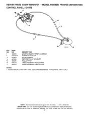
... AN * ARE LISTED AS REFERENCE FOR SERVICE PARTS ONLY. NOTE: All component dimensions given in U.S. REPAIR PARTS SNOW THROWER - - inches. 1 inch = 25.4 mm IMPORTANT: Use only Original Equipment Manufacturer (O.E.M.) replacement parts. MODEL NUMBER PR827ES (96192004302) CONTROL PANEL / CHUTE 2 2 *3 1 *7 *6 *4 01.09.010-B *5 KEY NO. 1 2 *3 *4 *5 *6 *7 PART NO. 428272 17501010 420678 405932 420675 428273 428310 DESCRIPTION LEVER/CABLE ROTATOR ASSEMBLY SCREW 10-24 X .625 ROTATOR HEAD ROTATOR PIVOT BRACKET PULLEY PIVOT CABLE ASSEMBLY ADJUSTABLE CABLE ASSEMBLY HEAT SHIELD NOTES...
... AN * ARE LISTED AS REFERENCE FOR SERVICE PARTS ONLY. NOTE: All component dimensions given in U.S. REPAIR PARTS SNOW THROWER - - inches. 1 inch = 25.4 mm IMPORTANT: Use only Original Equipment Manufacturer (O.E.M.) replacement parts. MODEL NUMBER PR827ES (96192004302) CONTROL PANEL / CHUTE 2 2 *3 1 *7 *6 *4 01.09.010-B *5 KEY NO. 1 2 *3 *4 *5 *6 *7 PART NO. 428272 17501010 420678 405932 420675 428273 428310 DESCRIPTION LEVER/CABLE ROTATOR ASSEMBLY SCREW 10-24 X .625 ROTATOR HEAD ROTATOR PIVOT BRACKET PULLEY PIVOT CABLE ASSEMBLY ADJUSTABLE CABLE ASSEMBLY HEAT SHIELD NOTES...
User Manual
Page 44
...This Warranty does not apply to any power equipment unit or attachment are belts, shear pins, normal wear, normal adjustments, standard hardware and normal maintenance. 6. For a period of two (2) years from defects in replacing parts, any part which has been subjected to alteration, misuse, abuse, improper assembly or installation, ...Please refer to the engine or components parts thereof. ID#, serial number and date of purchase of your product and the name and address of the authorized dealer from this warranty must return the product to an authorized service dealer. Some areas do...
...This Warranty does not apply to any power equipment unit or attachment are belts, shear pins, normal wear, normal adjustments, standard hardware and normal maintenance. 6. For a period of two (2) years from defects in replacing parts, any part which has been subjected to alteration, misuse, abuse, improper assembly or installation, ...Please refer to the engine or components parts thereof. ID#, serial number and date of purchase of your product and the name and address of the authorized dealer from this warranty must return the product to an authorized service dealer. Some areas do...


