
User Manual
Page 2
... to the State of residences, garages, porches or other ground level surfaces. Be thoroughly familiar with electric drive motors or electric starting the engine (motor). 3. Use extension cords and receptacles as roofs of California to a running (except when specifically recommended by the manufacturer for any repairs, adjustments or inspections. Exercise extreme caution when operating on clothing, change clothing immediately. 5. After striking a foreign object, stop the unit...
... to the State of residences, garages, porches or other ground level surfaces. Be thoroughly familiar with electric drive motors or electric starting the engine (motor). 3. Use extension cords and receptacles as roofs of California to a running (except when specifically recommended by the manufacturer for any repairs, adjustments or inspections. Exercise extreme caution when operating on clothing, change clothing immediately. 5. After striking a foreign object, stop the unit...
User Manual
Page 3
... out of this owner's manual. Maintain or replace safety and instruction labels, as wheel weights, counterweights, or cabs). 15. Should you cannot easily remedy, please contact your snow thrower properly. TABLE OF CONTENTS SAFETY RULES 2-3 MAINTENANCE 13-14 PRODUCT SPECIFICATIONS 3 SERVICE AND ADJUSTMENTS 15-17 CUSTOMER RESPONSIBILITIES 3 STORAGE 17 ASSEMBLY / PRE-OPERATION 4-7 TROUBLESHOOTING 18 OPERATION 8-12 REPAIR PARTS 20-37 MAINTENANCE SCHEDULE 13 3 WARRANTY BACK COVER Disconnect the spark plug wire and keep...
... out of this owner's manual. Maintain or replace safety and instruction labels, as wheel weights, counterweights, or cabs). 15. Should you cannot easily remedy, please contact your snow thrower properly. TABLE OF CONTENTS SAFETY RULES 2-3 MAINTENANCE 13-14 PRODUCT SPECIFICATIONS 3 SERVICE AND ADJUSTMENTS 15-17 CUSTOMER RESPONSIBILITIES 3 STORAGE 17 ASSEMBLY / PRE-OPERATION 4-7 TROUBLESHOOTING 18 OPERATION 8-12 REPAIR PARTS 20-37 MAINTENANCE SCHEDULE 13 3 WARRANTY BACK COVER Disconnect the spark plug wire and keep...
User Manual
Page 4
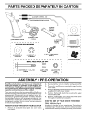
Cut down all packing materials except plastic tie holding speed control rod to lower handle. 5. Remove the two (2) screws securing the auger housing to the pallet. 6. To ensure safe and proper operation of your snow thrower, all accessible loose parts and parts boxes from carton and check carton thoroughly for shipping purposes. Remove all four corners of the belt cover. Remove snow thrower from carton. 4 located on your new snow thrower. Store the extra shear bolts, nuts and...
Cut down all packing materials except plastic tie holding speed control rod to lower handle. 5. Remove the two (2) screws securing the auger housing to the pallet. 6. To ensure safe and proper operation of your snow thrower, all accessible loose parts and parts boxes from carton and check carton thoroughly for shipping purposes. Remove all four corners of the belt cover. Remove snow thrower from carton. 4 located on your new snow thrower. Store the extra shear bolts, nuts and...

User Manual
Page 5
... loop on the end of the spring as shown. 2. INSTALL SPEED CONTROL ROD (See Figs. 1 and 2) 1. Remove plastic tie securing rod to lower handle. Additional carriage bolts, washers and handle knobs are in handles. ASSEMBLY / PRE-OPERATION NOTE: The multi-wrench may be used for assembly of the chute rotator head to snow thrower and making adjustments to the operating position and tighten handle knobs securely. UNFOLD UPPER HANDLE 1. Install in lower holes in bag...
... loop on the end of the spring as shown. 2. INSTALL SPEED CONTROL ROD (See Figs. 1 and 2) 1. Remove plastic tie securing rod to lower handle. Additional carriage bolts, washers and handle knobs are in handles. ASSEMBLY / PRE-OPERATION NOTE: The multi-wrench may be used for assembly of the chute rotator head to snow thrower and making adjustments to the operating position and tighten handle knobs securely. UNFOLD UPPER HANDLE 1. Install in lower holes in bag...

User Manual
Page 6
... hole in auger control bracket. ASSEMBLY / PRE-OPERATION INSTALL AUGER CONTROL ROD (See Figs. 5 and 6) The auger control rod has the short loop on rod and insert end of rod into control arm with holes in chute bracket. 3. CHUTE ROTATER HEAD 3/8 LOCKNUT 3/8 WASHER LOOP OPENING UP FIG. 5 AUGER CONTROL ROD AUGER CONTROL RETAINER LEVER SPRING PIN THREADED STUD CHUTE BRACKET ALIGN BEFORE TIGHTENING LOCKNUT FIG. 7 ROTATER HEAD MOUNTING BRACKET CHECK TIRE PRESSURE The tires...
... hole in auger control bracket. ASSEMBLY / PRE-OPERATION INSTALL AUGER CONTROL ROD (See Figs. 5 and 6) The auger control rod has the short loop on rod and insert end of rod into control arm with holes in chute bracket. 3. CHUTE ROTATER HEAD 3/8 LOCKNUT 3/8 WASHER LOOP OPENING UP FIG. 5 AUGER CONTROL ROD AUGER CONTROL RETAINER LEVER SPRING PIN THREADED STUD CHUTE BRACKET ALIGN BEFORE TIGHTENING LOCKNUT FIG. 7 ROTATER HEAD MOUNTING BRACKET CHECK TIRE PRESSURE The tires...

User Manual
Page 8
... FILLER CAP CHOKE CONTROL OPERATION ELECTRIC START BUTTON AUGER CONTROL LEVER POWER CORD PLUG DISCHARGE CHUTE CONTROL LEVER DRIVE SPEED CONTROL LEVER TRACTION DRIVE CONTROL LEVER CHUTE DEFLECTOR SAFETY IGNITION KEY ON / OFF SWITCH PRIMER FUEL SHUT-OFF VALVE RECOIL (AUXILIARY) STARTER HANDLE DISCHARGE CHUTE CLEAN-OUT TOOL LIGHT CHUTE DEFLECTOR KNOB HANDLE KNOB NOTE: ITEMS ABOVE ARE SHOWN IN THEIR TYPICAL LOCATION ON THE ENGINE. used to adjust height of snow thrower. Electric start and run. used for starting a cold engine. Traction drive control lever - Auger control lever...
... FILLER CAP CHOKE CONTROL OPERATION ELECTRIC START BUTTON AUGER CONTROL LEVER POWER CORD PLUG DISCHARGE CHUTE CONTROL LEVER DRIVE SPEED CONTROL LEVER TRACTION DRIVE CONTROL LEVER CHUTE DEFLECTOR SAFETY IGNITION KEY ON / OFF SWITCH PRIMER FUEL SHUT-OFF VALVE RECOIL (AUXILIARY) STARTER HANDLE DISCHARGE CHUTE CLEAN-OUT TOOL LIGHT CHUTE DEFLECTOR KNOB HANDLE KNOB NOTE: ITEMS ABOVE ARE SHOWN IN THEIR TYPICAL LOCATION ON THE ENGINE. used to adjust height of snow thrower. Electric start and run. used for starting a cold engine. Traction drive control lever - Auger control lever...

User Manual
Page 9
... USE YOUR SNOW THROWER Know how to start a warm engine. • To engage choke, move lever left or right until chute is located beneath the fuel tank on the engine. Always operate the snow thrower with the fuel shut-off valve is in which can result in the OPEN position. DISCHARGE CHUTE CONTROL LEVER OFF OPEN FIG. 9 TO USE CHOKE CONTROL (See Fig. 10) The choke control is controlled by the discharge chute control lever. • To change the deflector position, loosen knob...
... USE YOUR SNOW THROWER Know how to start a warm engine. • To engage choke, move lever left or right until chute is located beneath the fuel tank on the engine. Always operate the snow thrower with the fuel shut-off valve is in which can result in the OPEN position. DISCHARGE CHUTE CONTROL LEVER OFF OPEN FIG. 9 TO USE CHOKE CONTROL (See Fig. 10) The choke control is controlled by the discharge chute control lever. • To change the deflector position, loosen knob...

User Manual
Page 10
... drive control lever to handle to engage the drive system. • Release traction drive control lever to stop the forward or reverse movement of the snow thrower. CAUTION: Do not move lever to desired position BEFORE engaging the traction drive control lever. Be sure lever springs back and locks into the discharge chute to prevent accidental starting. • Release the auger control lever and shut off the engine. • Remove the clean-out tool from the handle and adjust...
... drive control lever to handle to engage the drive system. • Release traction drive control lever to stop the forward or reverse movement of the snow thrower. CAUTION: Do not move lever to desired position BEFORE engaging the traction drive control lever. Be sure lever springs back and locks into the discharge chute to prevent accidental starting. • Release the auger control lever and shut off the engine. • Remove the clean-out tool from the handle and adjust...
User Manual
Page 11
... oil or fuel. Be sure both plates are located on level ground. 2. When it has worn almost to stop. 2. Do not overfill. • To change engine oil, see "TO CHANGE ENGINE OIL" in the Maintenance section of tank filler neck. ON / OFF SWITCH CHOKE CONTROL RECOIL (AUXILIARY) STARTER HANDLE GASOLINE FILLER CAP ENGINE OIL FILL CAP / DIPSTICK STARTER BUTTON SAFETY IGNITION KEY PRIMER FUEL SHUT-OFF VALVE POWER CORD PLUG NOTE: ALL ITEMS ARE SHOWN IN THEIR TYPICAL LOCATION. Remove oil fill cap...
... oil or fuel. Be sure both plates are located on level ground. 2. When it has worn almost to stop. 2. Do not overfill. • To change engine oil, see "TO CHANGE ENGINE OIL" in the Maintenance section of tank filler neck. ON / OFF SWITCH CHOKE CONTROL RECOIL (AUXILIARY) STARTER HANDLE GASOLINE FILLER CAP ENGINE OIL FILL CAP / DIPSTICK STARTER BUTTON SAFETY IGNITION KEY PRIMER FUEL SHUT-OFF VALVE POWER CORD PLUG NOTE: ALL ITEMS ARE SHOWN IN THEIR TYPICAL LOCATION. Remove oil fill cap...

User Manual
Page 12
... engine, proceed as possible. 2. BEFORE STOPPING Run the engine for next use. 3. Rotate choke control to "FULL" position. 4. Pull recoil starter handle quickly. Do not allow engine to run for a few minutes to the "OFF" position. 8. Your snow thrower engine is equipped with a three-wire power cord and plug and is equipped with both a 120 Volt A.C. Disconnect the power cord from the receptacle first, then from starting engine with the electric starter. 6. RECOIL STARTER 1. Place ON / OFF switch...
... engine, proceed as possible. 2. BEFORE STOPPING Run the engine for next use. 3. Rotate choke control to "FULL" position. 4. Pull recoil starter handle quickly. Do not allow engine to run for a few minutes to the "OFF" position. 8. Your snow thrower engine is equipped with a three-wire power cord and plug and is equipped with both a 120 Volt A.C. Disconnect the power cord from the receptacle first, then from starting engine with the electric starter. 6. RECOIL STARTER 1. Place ON / OFF switch...

User Manual
Page 13
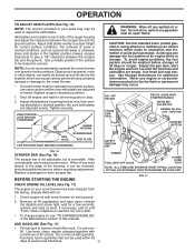
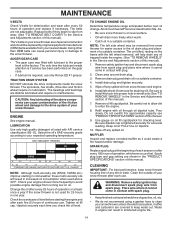
... make any maintenance. • Keep tires free of injury to operator abuse or negligence. TIRES • Maintain proper air pressure in this manual. • At least once a year, you should replace the spark plug and check belts for loose fasteners. 3. At least once a season, check to properly maintain your local parts dealer. Failure to do so can harm rubber. Check engine oil level. 2. BEFORE EACH USE 1. NOTE: To...
... make any maintenance. • Keep tires free of injury to operator abuse or negligence. TIRES • Maintain proper air pressure in this manual. • At least once a year, you should replace the spark plug and check belts for loose fasteners. 3. At least once a season, check to properly maintain your local parts dealer. Failure to do so can harm rubber. Check engine oil level. 2. BEFORE EACH USE 1. NOTE: To...
User Manual
Page 14
... snow thrower is on oil fill cap/dipstick for checking level. Place wire where it could create a fire hazard and/or damage. The belts are covered to the drive system of your engine oil level more freely when warm. • Catch oil in the Service and Adjustments section of this manual). 7. Tighten oil fill cap / dipstick securely each use only Ronex ED #1 grease. For approximate capacity see "PRODUCT SPECIFICATIONS" section of this manual. Spark plug type and gap setting...
... snow thrower is on oil fill cap/dipstick for checking level. Place wire where it could create a fire hazard and/or damage. The belts are covered to the drive system of your engine oil level more freely when warm. • Catch oil in the Service and Adjustments section of this manual). 7. Tighten oil fill cap / dipstick securely each use only Ronex ED #1 grease. For approximate capacity see "PRODUCT SPECIFICATIONS" section of this manual. Spark plug type and gap setting...

User Manual
Page 15
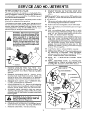
... STOP position. Remove safety ignition key. 3. Disengage all controls and move throttle control to any other components. Remove the two (2) screws securing belt cover to spark plug. Replace safety IMPELLER SHEAR BOLTS The impeller is in the Operation section of the bolts have completely stopped. 4. SNOW THROWER TO ADJUST SNOW THROWER HEIGHT See "TO ADJUST SKID PLATES" and "SCRAPER BAR" in the OFF position. 2. To replace the shear bolts: 1. Install 1/4-20 lock nut and tighten securely. Remove safety ignition key and disconnect spark plug wire from spark plug...
... STOP position. Remove safety ignition key. 3. Disengage all controls and move throttle control to any other components. Remove the two (2) screws securing belt cover to spark plug. Replace safety IMPELLER SHEAR BOLTS The impeller is in the Operation section of the bolts have completely stopped. 4. SNOW THROWER TO ADJUST SNOW THROWER HEIGHT See "TO ADJUST SKID PLATES" and "SCRAPER BAR" in the OFF position. 2. To replace the shear bolts: 1. Install 1/4-20 lock nut and tighten securely. Remove safety ignition key and disconnect spark plug wire from spark plug...
User Manual
Page 16
...from snow thrower. 3. REMOVE ENGINE PULLEY - WARNING: As the last bolt is inside belt keepers. 10. FRAME ASSEMBLY AUGER HOUSING HANDLES 8. Make sure belt is removed, have your assistant slowly raises handles to relieve tension. 9. See "INSTALL DISCHARGE CHUTE / CHUTE ROTATER HEAD" in the Assembly / Pre-Operation section of auger pulley only. 12. REMOVE GASOLINE FROM FUEL TANK - REMOVE BELT COVER - Remove outside (auger) pulley only from around and inside the groove of this manual. 4. SEPARATE SNOW THROWER - RELIEVE TENSION ON TRACTION DRIVE BELT IDLER and remove...
...from snow thrower. 3. REMOVE ENGINE PULLEY - WARNING: As the last bolt is inside belt keepers. 10. FRAME ASSEMBLY AUGER HOUSING HANDLES 8. Make sure belt is removed, have your assistant slowly raises handles to relieve tension. 9. See "INSTALL DISCHARGE CHUTE / CHUTE ROTATER HEAD" in the Assembly / Pre-Operation section of auger pulley only. 12. REMOVE GASOLINE FROM FUEL TANK - REMOVE BELT COVER - Remove outside (auger) pulley only from around and inside the groove of this manual. 4. SEPARATE SNOW THROWER - RELIEVE TENSION ON TRACTION DRIVE BELT IDLER and remove...

User Manual
Page 17
... if your snow thrower to make any enclosure. Inspect and replace belts, if necessary (See "TO REPLACE BELTS" in minimizing the formation of this manual. 4. Remove spark plug. 2. To disengage drive system from the wheels (for storage at altitudes up all nuts, bolts, screws, and pins are empty. • Never use engine or carburetor cleaner products in the Maintenance section of this manual). 3. If you think the engine-governed high speed needs adjusting, contact a qualified service center...
... if your snow thrower to make any enclosure. Inspect and replace belts, if necessary (See "TO REPLACE BELTS" in minimizing the formation of this manual. 4. Remove spark plug. 2. To disengage drive system from the wheels (for storage at altitudes up all nuts, bolts, screws, and pins are empty. • Never use engine or carburetor cleaner products in the Maintenance section of this manual). 3. If you think the engine-governed high speed needs adjusting, contact a qualified service center...
User Manual
Page 18
... fuel line. 3. Empty fuel tank & carburetor, refill with fresh, clean gasoline. 4. Contact an authorized service centre/department. Check / reinstall auger belt. 2. PROBLEM CAUSE CORRECTION Does not start 1. Fill fuel tank with fresh, clean gasoline. 5. Clean snow chute. 4. Water in OFF position. 6. Spark plug wire loose. 2. Drive belt is hard to pull 1. of pulley. 2. Remove debris or foreign object from augers / impeller. 18 Engine is in need of power 1. Drive belt is off valve to FAST position 5. Choke is flooded. 8. Stale fuel. 4. Loose parts...
... fuel line. 3. Empty fuel tank & carburetor, refill with fresh, clean gasoline. 4. Contact an authorized service centre/department. Check / reinstall auger belt. 2. PROBLEM CAUSE CORRECTION Does not start 1. Fill fuel tank with fresh, clean gasoline. 5. Clean snow chute. 4. Water in OFF position. 6. Spark plug wire loose. 2. Drive belt is hard to pull 1. of pulley. 2. Remove debris or foreign object from augers / impeller. 18 Engine is in need of power 1. Drive belt is off valve to FAST position 5. Choke is flooded. 8. Stale fuel. 4. Loose parts...

User Manual
Page 21
... damage your snow thrower and void your warranty. 21 inches. 1 inch = 25.4 mm IMPORTANT: Use only Original Equipment Manufacturer (O.E.M.) replacement parts. REPAIR PARTS SNOW THROWER - - ...ASSEMBLY BEARING IMPELLER PULLEY DISCHARGE BASE CORNER BRACKET CLEAN OUT TOOL TOOL CLIP NUT 1/4−20 SCREW 1/4−20 X .625 NUT 5/16−18 SCREW 5/16−18 X .625 WASHER LOCKWASHER 5/16 SCREW 5/16−18 X 1.00 CARRIAGE BOLT SCREW 13−16 X .625 PLUG GEARBOX COVER RH GASKET SEAL BEARING THRUST WASHER 1.00 WORM GEAR AUGER SHAFT SQUARE KEY BEARING THRUST WASHER IMPELLER SHAFT ROLL PIN...
... damage your snow thrower and void your warranty. 21 inches. 1 inch = 25.4 mm IMPORTANT: Use only Original Equipment Manufacturer (O.E.M.) replacement parts. REPAIR PARTS SNOW THROWER - - ...ASSEMBLY BEARING IMPELLER PULLEY DISCHARGE BASE CORNER BRACKET CLEAN OUT TOOL TOOL CLIP NUT 1/4−20 SCREW 1/4−20 X .625 NUT 5/16−18 SCREW 5/16−18 X .625 WASHER LOCKWASHER 5/16 SCREW 5/16−18 X 1.00 CARRIAGE BOLT SCREW 13−16 X .625 PLUG GEARBOX COVER RH GASKET SEAL BEARING THRUST WASHER 1.00 WORM GEAR AUGER SHAFT SQUARE KEY BEARING THRUST WASHER IMPELLER SHAFT ROLL PIN...

User Manual
Page 22
inches. 1 inch = 25.4 mm IMPORTANT: Use only Original Equipment Manufacturer (O.E.M.) replacement parts. Failure to do so could be hazardous, damage your snow thrower and void your warranty. 22 REPAIR PARTS SNOW THROWER - - MODEL NUMBER PR5524ESLCT (96192002501) AUGER HOUSING / IMPELLER ASSEMBLY 1 KEY NO. 1 2 3 4 PART NO. 404928X428 404931X479 72270505 155377 DESCRIPTION AUGER HOUSING SCRAPPER BAR CARRIAGE BOLT 5/16−18 X .625 NUT 5/16−18 3 (5x) 4 (5x) 2 01.07.001-A 2 1 KEY NO. 1 2 PART NO. 420493X479 420494X479 DESCRIPTION AUGER ASSEMBLY LH...
inches. 1 inch = 25.4 mm IMPORTANT: Use only Original Equipment Manufacturer (O.E.M.) replacement parts. Failure to do so could be hazardous, damage your snow thrower and void your warranty. 22 REPAIR PARTS SNOW THROWER - - MODEL NUMBER PR5524ESLCT (96192002501) AUGER HOUSING / IMPELLER ASSEMBLY 1 KEY NO. 1 2 3 4 PART NO. 404928X428 404931X479 72270505 155377 DESCRIPTION AUGER HOUSING SCRAPPER BAR CARRIAGE BOLT 5/16−18 X .625 NUT 5/16−18 3 (5x) 4 (5x) 2 01.07.001-A 2 1 KEY NO. 1 2 PART NO. 420493X479 420494X479 DESCRIPTION AUGER ASSEMBLY LH...

User Manual
Page 31
... 402652 DESCRIPTION SPEED SELECTOR ASSEMBLY SCREW 10−24 X .625 END PLATE SCREW 5/16−18 X .50 WASHER CONTROL ARM CLEVIS PIN SHIFTER PLATE SHOULDER BOLT SHIFTER BRACKET NUT 1/4−20 CLUTCH PLATE CLUTCH BRACKET SHIFTER LINK RETAINER CONTROL SHAFT CLUTCH ROD RETAINER SHIFTER YOKE PIVOT ROD RETAINER RETURN SPRING NUT 5/16−18 BEARING NUT 5/16−18 RUBBER WHEEL PLATE RUBBER RING BEARING WHEEL HUB SCREW 5/16...
... 402652 DESCRIPTION SPEED SELECTOR ASSEMBLY SCREW 10−24 X .625 END PLATE SCREW 5/16−18 X .50 WASHER CONTROL ARM CLEVIS PIN SHIFTER PLATE SHOULDER BOLT SHIFTER BRACKET NUT 1/4−20 CLUTCH PLATE CLUTCH BRACKET SHIFTER LINK RETAINER CONTROL SHAFT CLUTCH ROD RETAINER SHIFTER YOKE PIVOT ROD RETAINER RETURN SPRING NUT 5/16−18 BEARING NUT 5/16−18 RUBBER WHEEL PLATE RUBBER RING BEARING WHEEL HUB SCREW 5/16...

User Manual
Page 40
... you have any product which we will repair or replace, at our option, without charge for parts or labor incurred in replacing parts, any products used for any power equipment unit or attachment are belts, shear pins, normal wear, normal adjustments, standard hardware and normal maintenance. 6. Please refer to the following limitations and exclusions. 1. This Warranty gives you specific legal rights, and you may not...
... you have any product which we will repair or replace, at our option, without charge for parts or labor incurred in replacing parts, any products used for any power equipment unit or attachment are belts, shear pins, normal wear, normal adjustments, standard hardware and normal maintenance. 6. Please refer to the following limitations and exclusions. 1. This Warranty gives you specific legal rights, and you may not...


