

User Manual
Page 2
... enter the area. • Before and when backing, look down and behind and down the slope. Reduced traction could expose moving parts or allow responsible adults, who are involved in daylight or good artificial light. • Do not operate the machine while under the... the blades and proceed slowly straight down for small children. • Never carry children. Frequently check components and replace with manufacturer's recommended parts, when necessary. • Mower blades are often attracted to protect themselves and others from serious injury. SERVICE • Use extra care ...
... enter the area. • Before and when backing, look down and behind and down the slope. Reduced traction could expose moving parts or allow responsible adults, who are involved in daylight or good artificial light. • Do not operate the machine while under the... the blades and proceed slowly straight down for small children. • Never carry children. Frequently check components and replace with manufacturer's recommended parts, when necessary. • Mower blades are often attracted to protect themselves and others from serious injury. SERVICE • Use extra care ...

User Manual
Page 4
... CUSTOMER RESPONSIBILITIES 4, 16-19 ASSEMBLY 6-8 OPERATION 9-15 MAINTENANCE SCHEDULE 16 SERVICE AND ADJUSTMENTS 20-25 STORAGE 26 TROUBLESHOOTING 27-28 REPAIR PARTS - Always observe the "SAFETY RULES". Other states may have competent, well-trained technicians and the proper tools to give you to ... it should not be maintained in maintaining, caring for the muffler is available through your nearest authorized service center/department (See REPAIR PARTS section of a new tractor. A spark arrester for and using your purchase of this tractor. Federal laws apply on or near any...
... CUSTOMER RESPONSIBILITIES 4, 16-19 ASSEMBLY 6-8 OPERATION 9-15 MAINTENANCE SCHEDULE 16 SERVICE AND ADJUSTMENTS 20-25 STORAGE 26 TROUBLESHOOTING 27-28 REPAIR PARTS - Always observe the "SAFETY RULES". Other states may have competent, well-trained technicians and the proper tools to give you to ... it should not be maintained in maintaining, caring for the muffler is available through your nearest authorized service center/department (See REPAIR PARTS section of a new tractor. A spark arrester for and using your purchase of this tractor. Federal laws apply on or near any...

User Manual
Page 5
UNASSEMBLED PARTS Steering Wheel Seat Steering Sleeve Steering Wheel Insert Steering Extension Shaft (1) Hex Bolt 3/8-16 x 1 Steering Adapter (1) Large Flat Washer (1) Washer 17/32 x 1-3/16 x 12 Gauge (1) Knob (1) Oil Drain Tube For Future Use Slope Sheet (1) Lock washer 3/8 (1) Locknut 5/16-18 (1) Hex Bolt 5/16-18 x 1-1/4 (2) Mulch Blades 5 (2) Keys
UNASSEMBLED PARTS Steering Wheel Seat Steering Sleeve Steering Wheel Insert Steering Extension Shaft (1) Hex Bolt 3/8-16 x 1 Steering Adapter (1) Large Flat Washer (1) Washer 17/32 x 1-3/16 x 12 Gauge (1) Knob (1) Oil Drain Tube For Future Use Slope Sheet (1) Lock washer 3/8 (1) Locknut 5/16-18 (1) Hex Bolt 5/16-18 x 1-1/4 (2) Mulch Blades 5 (2) Keys
User Manual
Page 6
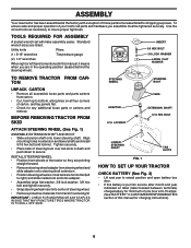
...wrenches Tire pressure gauge (2) 1/2" wrenches When right or left hand is put into service after month and year indicated on all accessible loose parts and parts cartons from carton. • Cut, from top to bottom, along lines on label (label located between terminals) charge battery for minimum of...TRACTOR FROM CARTON UNPACK CARTON • Remove all four corners of carton, and lay panels flat. • Check for any additional loose parts or cartons and remove. STEERING WHEEL ADAPTER 5/16 LOCKNUT STEERING BOOT TABS EXTENSION SHAFT 5/16 HEX BOLT LOWER STEERING SHAFT TAB SLOTS FIG....
...wrenches Tire pressure gauge (2) 1/2" wrenches When right or left hand is put into service after month and year indicated on all accessible loose parts and parts cartons from carton. • Cut, from top to bottom, along lines on label (label located between terminals) charge battery for minimum of...TRACTOR FROM CARTON UNPACK CARTON • Remove all four corners of carton, and lay panels flat. • Check for any additional loose parts or cartons and remove. STEERING WHEEL ADAPTER 5/16 LOCKNUT STEERING BOOT TABS EXTENSION SHAFT 5/16 HEX BOLT LOWER STEERING SHAFT TAB SLOTS FIG....

User Manual
Page 8
... EXTRA ATTENTION TO THE FOLLOWING IMPORTANT ITEMS: ! their location and function. Be sure brake system is now ready for the first time. No remaining loose parts in a safe place. Be sure they are properly clamped. ! Check wiring. DEFLECTOR SHIELD MULCHER PLATE LATCH HOOKS FIG. 4 TO CONVERT TO BAGGING OR DISCHARGING NOTE...
... EXTRA ATTENTION TO THE FOLLOWING IMPORTANT ITEMS: ! their location and function. Be sure brake system is now ready for the first time. No remaining loose parts in a safe place. Be sure they are properly clamped. ! Check wiring. DEFLECTOR SHIELD MULCHER PLATE LATCH HOOKS FIG. 4 TO CONVERT TO BAGGING OR DISCHARGING NOTE...

User Manual
Page 17
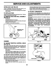
BRAKE OPERATION If tractor requires more than six (6) feet stopping distance at 6-10 amperes for 1 hour. If your local parts dealer. but are working properly. Care should remain in BATTERY FIG. 13 exact order as shown. The lobes of this manual). • Keep tires free ...
BRAKE OPERATION If tractor requires more than six (6) feet stopping distance at 6-10 amperes for 1 hour. If your local parts dealer. but are working properly. Care should remain in BATTERY FIG. 13 exact order as shown. The lobes of this manual). • Keep tires free ...

User Manual
Page 20
... all moving retainer spring. • Disconnect suspension arms from rear deck brackets by removing retainer springs. • Disconnect front links from deck by re- moving parts have completely stopped. • Disconnect spark plug wire from spark plug and place wire where it cannot come in contact with discharge guard to right...
... all moving retainer spring. • Disconnect suspension arms from rear deck brackets by removing retainer springs. • Disconnect front links from deck by re- moving parts have completely stopped. • Disconnect spark plug wire from spark plug and place wire where it cannot come in contact with discharge guard to right...

User Manual
Page 23
... height to the lowest position. FRONT WHEEL TOE-IN/CAMBER The front wheel toe-in the direction it should not be purchased from your local parts dealer. Do not lose). • Repair tire and reassemble. • On rear wheels only: align grooves in axle groove. • Replace axle cover. WASHERS RETAINING...
... height to the lowest position. FRONT WHEEL TOE-IN/CAMBER The front wheel toe-in the direction it should not be purchased from your local parts dealer. Do not lose). • Repair tire and reassemble. • On rear wheels only: align grooves in axle groove. • Replace axle cover. WASHERS RETAINING...
User Manual
Page 25
... . SERVICE AND ADJUSTMENTS INTERLOCKS AND RELAYS Loose or damaged wiring may result. TO REPLACE FUSE Replace with 20 amp automotive-type plug-in the Repair Parts section. TO ADJUST CARBURETOR Your carburetor is located behind the dash.
... . SERVICE AND ADJUSTMENTS INTERLOCKS AND RELAYS Loose or damaged wiring may result. TO REPLACE FUSE Replace with 20 amp automotive-type plug-in the Repair Parts section. TO ADJUST CARBURETOR Your carburetor is located behind the dash.
User Manual
Page 26
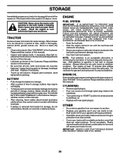
... the engine to cool before painting. ENGINE FUEL SYSTEM IMPORTANT: IT IS IMPORTANT TO PREVENT GUM DEPOSITS FROM FORMING IN ESSENTIAL FUEL SYSTEM PARTS SUCH AS CARBURETOR, FUEL FILTER, FUEL HOSE, OR TANK DURING STORAGE. Do not drain the gas tank and carburetor if using fuel ... stabilizer to reach the carburetor. Store in a clean, dry area. • Clean entire tractor (See "CLEANING" in any enclosure. Inspect moving parts for damage, breakage and wear. Do not use engine or carburetor cleaner products in the Customer Responsibilities section of this manual). • After cleaning,...
... the engine to cool before painting. ENGINE FUEL SYSTEM IMPORTANT: IT IS IMPORTANT TO PREVENT GUM DEPOSITS FROM FORMING IN ESSENTIAL FUEL SYSTEM PARTS SUCH AS CARBURETOR, FUEL FILTER, FUEL HOSE, OR TANK DURING STORAGE. Do not drain the gas tank and carburetor if using fuel ... stabilizer to reach the carburetor. Store in a clean, dry area. • Clean entire tractor (See "CLEANING" in any enclosure. Inspect moving parts for damage, breakage and wear. Do not use engine or carburetor cleaner products in the Customer Responsibilities section of this manual). • After cleaning,...

User Manual
Page 27
... level/dirty oil. 6. Spark plug wire loose. 11. Replace fuel filter. 8. Excessive vibration 1. Bent blade mandrel. 3. Tighten loose part(s). TROUBLESHOOTING POINTS PROBLEM Will not start 1. Bad spark plug. 5. See "To Adjust Carburetor" in "CHOKE" position. 3. Contact an ... 7. Disengage attachment clutch. 3. Check/replace ignition switch. 8. Carburetor out of adjustment. Connect and tighten spark plug wire. 11. Loose/damaged part(s). 1. Replace blade mandrel. 3. Engine flooded. 4. Dirty air filter. 6. Loose or damaged wiring. 7. Build-up of power 1. Dirty/...
... level/dirty oil. 6. Spark plug wire loose. 11. Replace fuel filter. 8. Excessive vibration 1. Bent blade mandrel. 3. Tighten loose part(s). TROUBLESHOOTING POINTS PROBLEM Will not start 1. Bad spark plug. 5. See "To Adjust Carburetor" in "CHOKE" position. 3. Contact an ... 7. Disengage attachment clutch. 3. Check/replace ignition switch. 8. Carburetor out of adjustment. Connect and tighten spark plug wire. 11. Loose/damaged part(s). 1. Replace blade mandrel. 3. Engine flooded. 4. Dirty air filter. 6. Loose or damaged wiring. 7. Build-up of power 1. Dirty/...

User Manual
Page 31
REPAIR PARTS TRACTOR - - inches 1 inch = 25.4 mm 31 DESCRIPTION 1 163465 2 74760412 8 156417 16 153664 21 166181 22 4152J 24 4799J 25 146147 26 175158 27 73510400 28 ... Ign Molded Generic Harness Ign Bolt Fin Hex 1/4-20uncx 1/2 Cover Terminal Red Solenoid Ammeter Rectangular Protection Loop NOTE: All component dimensions given in U.S. MODEL NUMBER PR20H42STC ELECTRICAL KEY PART NO. NO.
REPAIR PARTS TRACTOR - - inches 1 inch = 25.4 mm 31 DESCRIPTION 1 163465 2 74760412 8 156417 16 153664 21 166181 22 4152J 24 4799J 25 146147 26 175158 27 73510400 28 ... Ign Molded Generic Harness Ign Bolt Fin Hex 1/4-20uncx 1/2 Cover Terminal Red Solenoid Ammeter Rectangular Protection Loop NOTE: All component dimensions given in U.S. MODEL NUMBER PR20H42STC ELECTRICAL KEY PART NO. NO.

User Manual
Page 32
MODEL NUMBER PR20H42STC CHASSIS 17 159 30 24 212 29 18 24 12 28 25 26 31 3 208 25 26 5 5 53 51 58 52 55 57 208 11 9 207 208 207 54 20 23 26 64 3 35 3 33 3 10 3 142 207 1 13 2 206 37 145 37 3 3 142 3 3 208 14 35 3 14 38 34 26 32 REPAIR PARTS TRACTOR - -
MODEL NUMBER PR20H42STC CHASSIS 17 159 30 24 212 29 18 24 12 28 25 26 31 3 208 25 26 5 5 53 51 58 52 55 57 208 11 9 207 208 207 54 20 23 26 64 3 35 3 33 3 10 3 142 207 1 13 2 206 37 145 37 3 3 142 3 3 208 14 35 3 14 38 34 26 32 REPAIR PARTS TRACTOR - -

User Manual
Page 33
... Screw Thdrol 5/16-18 x 1/2 208 17670608 Screw Thdrol 3/8-16 x 1/2 212 156229 Insert Lens Relect --- 5479J Plug BTN. Blk NOTE: All component dimensions given in U.S. REPAIR PARTS TRACTOR - - inches 1 inch = 25.4 mm 33 MODEL NUMBER PR20H42STC CHASSIS KEY PART NO.
... Screw Thdrol 5/16-18 x 1/2 208 17670608 Screw Thdrol 3/8-16 x 1/2 212 156229 Insert Lens Relect --- 5479J Plug BTN. Blk NOTE: All component dimensions given in U.S. REPAIR PARTS TRACTOR - - inches 1 inch = 25.4 mm 33 MODEL NUMBER PR20H42STC CHASSIS KEY PART NO.

User Manual
Page 34
MODEL NUMBER PR20H42STC DRIVE 51 57 89 69 197 81 32 30 52 16 95 77 15 96 1 26 63 169 198 161 159 158 59 162 61 14 164 21 163 83 168 10 82 165 156 166 56 41 40 38 8 35 62 36 52 32 212 66 65 64 50 70 116 202 150 48 151 42 27 51 49 39 47 120 34 37 36 35 30 16 26 29 28 26 16 22 84 27 24 19 26 25 200 61 77 71 199 61 74 75 78 76 73 16 53 55 34 REPAIR PARTS TRACTOR - -
MODEL NUMBER PR20H42STC DRIVE 51 57 89 69 197 81 32 30 52 16 95 77 15 96 1 26 63 169 198 161 159 158 59 162 61 14 164 21 163 83 168 10 82 165 156 166 56 41 40 38 8 35 62 36 52 32 212 66 65 64 50 70 116 202 150 48 151 42 27 51 49 39 47 120 34 37 36 35 30 16 26 29 28 26 16 22 84 27 24 19 26 25 200 61 77 71 199 61 74 75 78 76 73 16 53 55 34 REPAIR PARTS TRACTOR - -

User Manual
Page 35
...16 UNC x 1-1/4 V-Belt, Ground Drive Keeper, Center Span Screw Thdrol. 3/8-16 x .75 Cover, Pedal Pulley, Engine KEY PART NO. NO. inches 1 inch = 25.4 mm 35 NO. 1 ------ 8 165619 10 76020416 14 10040400 15 74490544 16 ...56 17060616 57 140294 59 169691 61 17060612 62 8883R 63 175410 DESCRIPTION Transaxle Hydro Gear 314-0510 (Order Parts From Transaxle Manufacturer) Rod Shift Hydro LT Pin Cotter 1/8 x 1 CAD Washer Lock Hvy Helical Bolt, ...212 145212 Nut Hex Flange Lock NOTE: All component dimensions given in U.S. REPAIR PARTS TRACTOR - - MODEL NUMBER PR20H42STC DRIVE KEY PART NO.
...16 UNC x 1-1/4 V-Belt, Ground Drive Keeper, Center Span Screw Thdrol. 3/8-16 x .75 Cover, Pedal Pulley, Engine KEY PART NO. NO. inches 1 inch = 25.4 mm 35 NO. 1 ------ 8 165619 10 76020416 14 10040400 15 74490544 16 ...56 17060616 57 140294 59 169691 61 17060612 62 8883R 63 175410 DESCRIPTION Transaxle Hydro Gear 314-0510 (Order Parts From Transaxle Manufacturer) Rod Shift Hydro LT Pin Cotter 1/8 x 1 CAD Washer Lock Hvy Helical Bolt, ...212 145212 Nut Hex Flange Lock NOTE: All component dimensions given in U.S. REPAIR PARTS TRACTOR - - MODEL NUMBER PR20H42STC DRIVE KEY PART NO.

User Manual
Page 36
MODEL NUMBER PR20H42STC STEERING ASSEMBLY 38 63 11 39 1 37 44 51 91 43 41 42 37 36 54 88 71 29 29 17 68 29 15 15 15 82 29 46 8 6 2 87 5 68 67 13 65 46 8 6 67 67 3 32 11 40 33 34 10 35 87 5 4 43 43 6 8 36 REPAIR PARTS TRACTOR - -
MODEL NUMBER PR20H42STC STEERING ASSEMBLY 38 63 11 39 1 37 44 51 91 43 41 42 37 36 54 88 71 29 29 17 68 29 15 15 15 82 29 46 8 6 2 87 5 68 67 13 65 46 8 6 67 67 3 32 11 40 33 34 10 35 87 5 4 43 43 6 8 36 REPAIR PARTS TRACTOR - -

User Manual
Page 37
... Flat .781 x 1 1/2 x .14 88 175118 Bolt Shoulder 7/16-20 91 175553 Clip Steering NOTE: All component dimensions given in U.S. inches 1 inch = 25.4 mm 37 REPAIR PARTS TRACTOR - - MODEL NUMBER PR20H42STC STEERING ASSEMBLY KEY PART NO. NO.
... Flat .781 x 1 1/2 x .14 88 175118 Bolt Shoulder 7/16-20 91 175553 Clip Steering NOTE: All component dimensions given in U.S. inches 1 inch = 25.4 mm 37 REPAIR PARTS TRACTOR - - MODEL NUMBER PR20H42STC STEERING ASSEMBLY KEY PART NO. NO.

User Manual
Page 38
... Lock W/Ins 5/16-18 Washer 17/32 X 1-3/16 X 12 Ga. REPAIR PARTS TRACTOR - - inches 1 inch = 25.4 mm 38 Pan Seat Knob Seat Bracket Mounting Switch KEY PART NO. Bolt Shoulder 5/16-18 X 62 NOTE: All component dimensions given in U.S. MODEL NUMBER PR20H42STC SEAT ASSEMBLY 1 14 24 8 9 7 10 5 8 9 7 5 6 22 2 21 16 25 15 11...
... Lock W/Ins 5/16-18 Washer 17/32 X 1-3/16 X 12 Ga. REPAIR PARTS TRACTOR - - inches 1 inch = 25.4 mm 38 Pan Seat Knob Seat Bracket Mounting Switch KEY PART NO. Bolt Shoulder 5/16-18 X 62 NOTE: All component dimensions given in U.S. MODEL NUMBER PR20H42STC SEAT ASSEMBLY 1 14 24 8 9 7 10 5 8 9 7 5 6 22 2 21 16 25 15 11...

User Manual
Page 39
...Reflector Lh Manual Owner's (English) Manual Owner's (French) KEY PART NO. inches 1 inch = 25.4 mm 39 REPAIR PARTS TRACTOR - - MODEL NUMBER PR20H42STC DECALS 2 11 9 16 4 43 10 2 20 1 8 6 5 14 KEY NO. 1 2 3 4 5 6 8 PART NO. 157032 176303 176308 177020 170851 169210 170563 9 172740 10 ...Decal By Pass Lt Hydro Decal Mower Warn Keep Hand Away Decal Fender Logo Decal Fender Danger E/F WHEELS AND TIRES 1 2 5,8 4,10 7 3,9 6 11 KEY PART NO. Tube) NOTE: All component dimensions given in U.S. NO. DESCRIPTION 1 59192 Cap Valve Tire 2 65139 Stem Valve 3 170455 Tire F T 15 X 6...
...Reflector Lh Manual Owner's (English) Manual Owner's (French) KEY PART NO. inches 1 inch = 25.4 mm 39 REPAIR PARTS TRACTOR - - MODEL NUMBER PR20H42STC DECALS 2 11 9 16 4 43 10 2 20 1 8 6 5 14 KEY NO. 1 2 3 4 5 6 8 PART NO. 157032 176303 176308 177020 170851 169210 170563 9 172740 10 ...Decal By Pass Lt Hydro Decal Mower Warn Keep Hand Away Decal Fender Logo Decal Fender Danger E/F WHEELS AND TIRES 1 2 5,8 4,10 7 3,9 6 11 KEY PART NO. Tube) NOTE: All component dimensions given in U.S. NO. DESCRIPTION 1 59192 Cap Valve Tire 2 65139 Stem Valve 3 170455 Tire F T 15 X 6...


