
User Manual
Page 2
... under rotating parts. • Exercise extreme caution when operating on electric motors. • Do not run the engine indoors; exhaust fumes are present, such as specified by manufacturer). CAUTION: Always disconnect spark plug wire and place wire where it is generally a warning of the equipment. Allow the engine to cool before starting when setting up spilled fuel before restarting and operating the tiller. •...
... under rotating parts. • Exercise extreme caution when operating on electric motors. • Do not run the engine indoors; exhaust fumes are present, such as specified by manufacturer). CAUTION: Always disconnect spark plug wire and place wire where it is generally a warning of the equipment. Allow the engine to cool before starting when setting up spilled fuel before restarting and operating the tiller. •...
User Manual
Page 3
... 5w-30(Below 32°F/0°C) Champion RC12YC CONGRATULATIONS on your tiller. • Follow instructions under "Maintenance" and "Storage" sections of a new tiller. OTHER STATES MAY HAVE SIMILAR LAWS. Please read and retain this manual. TABLE OF CONTENTS SAFETY RULES 2 PRODUCT SPECIFICATIONS 3 CUSTOMER RESPONSIBILITIES 3 ASSEMBLY 4-5 OPERATION 6-9 MAINTENANCE SCHEDULE 10 MAINTENANCE 10-12 SERVICE & ADJUSTMENTS 12-14 STORAGE 15 TROUBLESHOOTING 16 REPAIR PARTS 17WARRANTY 17 3 FEDERAL LAWS APPLY...
... 5w-30(Below 32°F/0°C) Champion RC12YC CONGRATULATIONS on your tiller. • Follow instructions under "Maintenance" and "Storage" sections of a new tiller. OTHER STATES MAY HAVE SIMILAR LAWS. Please read and retain this manual. TABLE OF CONTENTS SAFETY RULES 2 PRODUCT SPECIFICATIONS 3 CUSTOMER RESPONSIBILITIES 3 ASSEMBLY 4-5 OPERATION 6-9 MAINTENANCE SCHEDULE 10 MAINTENANCE 10-12 SERVICE & ADJUSTMENTS 12-14 STORAGE 15 TROUBLESHOOTING 16 REPAIR PARTS 17WARRANTY 17 3 FEDERAL LAWS APPLY...
User Manual
Page 4
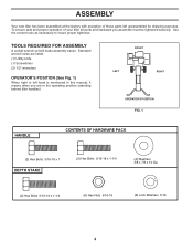
... OPERATOR'S POSITION FIG. 1 HANDLE CONTENTS OF HARDWARE PACK (2) Hex Bolts 5/16-18 x 1 DEPTH STAKE (2) Hex Bolts 5/16-18 x 1-1/4 (4) Washers 3/8 x 7/8 x 14 Ga. (2) Hex Bolts 5/16-18 x 1-1/4 (6) Hex Nuts 5/16-18 (6) Lock Washers 5/16 4 Use the correct tools as necessary to insure proper tightness. ASSEMBLY Your new tiller has been assembled at the factory with exception of your tiller all parts and hardware you are listed. (1) Utility knife (1) Screwdriver (2) 1/2" wrenches OPERATOR'S POSITION...
... OPERATOR'S POSITION FIG. 1 HANDLE CONTENTS OF HARDWARE PACK (2) Hex Bolts 5/16-18 x 1 DEPTH STAKE (2) Hex Bolts 5/16-18 x 1-1/4 (4) Washers 3/8 x 7/8 x 14 Ga. (2) Hex Bolts 5/16-18 x 1-1/4 (6) Hex Nuts 5/16-18 (6) Lock Washers 5/16 4 Use the correct tools as necessary to insure proper tightness. ASSEMBLY Your new tiller has been assembled at the factory with exception of your tiller all parts and hardware you are listed. (1) Utility knife (1) Screwdriver (2) 1/2" wrenches OPERATOR'S POSITION...

User Manual
Page 5
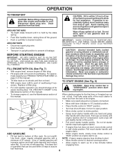
... support bolt. TINE OPERATION • Check tine operation before first use. (See "TINE OPERATION CHECK" in the Service and Adjustments section of this manual). Repeat for opposite side. FIG. 2 5 Tighten all hardware securely. • Cut cable ties securing tiller to skid and remove tiller from skid. • Remove screws securing depth stake to better handle your tilling conditions (See "TINE ARRANGEMENT" in lower hole of cartoning material. LOCK NUT WASHER TILLER HANDLE HANDLE...
... support bolt. TINE OPERATION • Check tine operation before first use. (See "TINE OPERATION CHECK" in the Service and Adjustments section of this manual). Repeat for opposite side. FIG. 2 5 Tighten all hardware securely. • Cut cable ties securing tiller to skid and remove tiller from skid. • Remove screws securing depth stake to better handle your tilling conditions (See "TINE ARRANGEMENT" in lower hole of cartoning material. LOCK NUT WASHER TILLER HANDLE HANDLE...

User Manual
Page 6
... tiller will dig. Controls engine speed. Engages tines in forward THROTTLE CONTROL - Used when starting a cold engine. direction. Save this manual for future reference. FORWARD TINE CONTROL REVERSE TINE CONTROL DEPTH STAKE RECOIL STARTER HANDLE CHOKE CONTROL THROTTLE CONTROL TINE SHIELD TINES FIG. 4 MEETS ANSI SAFETY REQUIREMENTS Our tillers conform to start the engine. OPERATION KNOW YOUR TILLER READ THIS MANUAL AND SAFETY RULES BEFORE OPERATING YOUR TILLER. direction. 6 Used to the safety standards of various controls and adjustments...
... tiller will dig. Controls engine speed. Engages tines in forward THROTTLE CONTROL - Used when starting a cold engine. direction. Save this manual for future reference. FORWARD TINE CONTROL REVERSE TINE CONTROL DEPTH STAKE RECOIL STARTER HANDLE CHOKE CONTROL THROTTLE CONTROL TINE SHIELD TINES FIG. 4 MEETS ANSI SAFETY REQUIREMENTS Our tillers conform to start the engine. OPERATION KNOW YOUR TILLER READ THIS MANUAL AND SAFETY RULES BEFORE OPERATING YOUR TILLER. direction. 6 Used to the safety standards of various controls and adjustments...

User Manual
Page 7
... the position of any tiller can result in severe eye damage. ENGINE • Move throttle control to "STOP" position. • Never use choke to start engine. Change wheel position. REVERSE • With forward tine control "OFF" (up) position, pull back and hold reverse tine control. 7 STAKE SPRING WHEEL FIG. 6 DEPTH STAKE ment. • Release reverse tine control to penetrate the ground. Replace the clevis pin and hairpin clip. • For normal tilling, set wheels...
... the position of any tiller can result in severe eye damage. ENGINE • Move throttle control to "STOP" position. • Never use choke to start engine. Change wheel position. REVERSE • With forward tine control "OFF" (up) position, pull back and hold reverse tine control. 7 STAKE SPRING WHEEL FIG. 6 DEPTH STAKE ment. • Release reverse tine control to penetrate the ground. Replace the clevis pin and hairpin clip. • For normal tilling, set wheels...
User Manual
Page 8
... spark plug wire. USE CLEAN FILL FUNNELS. imate capacity see the Maintenance section of fuel tank to prevent spills and to half choke position. To avoid engine problems, the fuel system should change engine oil, see "PRODUCT SPECIFICATIONS" on its wheels and then re-level. • With engine level, refill to choke position. Drain the gas tank, start of spill. Never use gasoline near an open position. • Move choke control to point of fuel, it is accidentally spilled, move choke control to...
... spark plug wire. USE CLEAN FILL FUNNELS. imate capacity see the Maintenance section of fuel tank to prevent spills and to half choke position. To avoid engine problems, the fuel system should change engine oil, see "PRODUCT SPECIFICATIONS" on its wheels and then re-level. • With engine level, refill to choke position. Drain the gas tank, start of spill. Never use gasoline near an open position. • Move choke control to point of fuel, it is accidentally spilled, move choke control to...
User Manual
Page 9
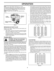
... the Service and Adjustments section of this manual. SPARK PLUG CHOKE CONTROL THROTTLE CONTROL RECOIL STARTER HANDLE engine_art_71 FIG. 8 BREAKING IN YOUR TILLER Break-in your tiller, start actual field use the depth stake. TILLING HINTS CAUTION: Until you are accustomed to start , see troubleshooting points. To help retain moisture in the soil being tilled.The proper setting of the wheels and depth stake is through trial and error...
... the Service and Adjustments section of this manual. SPARK PLUG CHOKE CONTROL THROTTLE CONTROL RECOIL STARTER HANDLE engine_art_71 FIG. 8 BREAKING IN YOUR TILLER Break-in your tiller, start actual field use the depth stake. TILLING HINTS CAUTION: Until you are accustomed to start , see troubleshooting points. To help retain moisture in the soil being tilled.The proper setting of the wheels and depth stake is through trial and error...
User Manual
Page 10
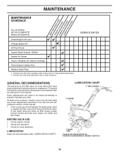
... fasteners. LUBRICATION CHART c TINE CONTROL d ENGINE c IDLER ARM cSAE 30 OR 10W-30 MOTOR OIL dREFER TO MAINTENANCE "ENGINE" SECTION 10 MAINTENANCE SCHEDULE MAINTENANCE EEEBVVVEFEEERRROYYYRE55205EHAHHOCOOUHUURRRSUSSSE FILL IN DATES AS YOU COMPLETE REGULAR SERVICE Check Engine Oil Level Change Engine Oil Oil Pivot Points Inspect Spark Arrester / Muffler Inspect Air Screen Clean or Replace Air Cleaner Cartridge 2 Clean Engine Cylinder Fins Replace Spark Plug 1 - Change more often when operating in the Service and Adjustments section of the adjustments described in dirty or dusty...
... fasteners. LUBRICATION CHART c TINE CONTROL d ENGINE c IDLER ARM cSAE 30 OR 10W-30 MOTOR OIL dREFER TO MAINTENANCE "ENGINE" SECTION 10 MAINTENANCE SCHEDULE MAINTENANCE EEEBVVVEFEEERRROYYYRE55205EHAHHOCOOUHUURRRSUSSSE FILL IN DATES AS YOU COMPLETE REGULAR SERVICE Check Engine Oil Level Change Engine Oil Oil Pivot Points Inspect Spark Arrester / Muffler Inspect Air Screen Clean or Replace Air Cleaner Cartridge 2 Clean Engine Cylinder Fins Replace Spark Plug 1 - Change more often when operating in the Service and Adjustments section of the adjustments described in dirty or dusty...

User Manual
Page 11
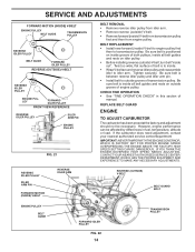
... expected temperature. Keep the engine free of the cartridge. Remove fuel from running low on level surface. • Oil will result in the Operation section of this manual. They may cause burns. AIR CLEANER CARTRIDGE COVER AIR CLEANER SCREW FIG. 13 COOLING SYSTEM (See Fig. 14) Your engine is on oil. OIL DRAIN PLUG engine_art_12 OIL FILLER PLUG OIL LEVEL MUFFLER FIG. 12 11 CYLINDER FINS engine_art_71 FIG. 14 BLOWER HOUSING AIR SCREEN Clean muffler area...
... expected temperature. Keep the engine free of the cartridge. Remove fuel from running low on level surface. • Oil will result in the Operation section of this manual. They may cause burns. AIR CLEANER CARTRIDGE COVER AIR CLEANER SCREW FIG. 13 COOLING SYSTEM (See Fig. 14) Your engine is on oil. OIL DRAIN PLUG engine_art_12 OIL FILLER PLUG OIL LEVEL MUFFLER FIG. 12 11 CYLINDER FINS engine_art_71 FIG. 14 BLOWER HOUSING AIR SCREEN Clean muffler area...

User Manual
Page 12
.... Replace if damaged. TILLER TO ADJUST HANDLE HEIGHT (See Fig. 15) Factory assembly has provided lowest handle height. Do not tamper with plug. Inspect periodically and replace if necessary. Spark plug type and gap setting are covered to holes "C" in "PRODUCT SPECIFICATIONS" on page 3 of your tiller when the engine and transmission are sharp. CAUTION: Tines are hot. MAINTENANCE MUFFLER Do not operate tiller without muffler. We do not recommend using pressurized...
.... Replace if damaged. TILLER TO ADJUST HANDLE HEIGHT (See Fig. 15) Factory assembly has provided lowest handle height. Do not tamper with plug. Inspect periodically and replace if necessary. Spark plug type and gap setting are covered to holes "C" in "PRODUCT SPECIFICATIONS" on page 3 of your tiller when the engine and transmission are sharp. CAUTION: Tines are hot. MAINTENANCE MUFFLER Do not operate tiller without muffler. We do not recommend using pressurized...

User Manual
Page 13
... belt guard is under head of tine shield bolt and all slack removed from spark plug to relieve spring tension. TINE OPERATION CHECK (See Fig. 19) FIG. 19 WARNING: Disconnect spark plug wire from inner wire of cable. TINE SHIELD NUT FIG. 20 TO REPLACE V-BELTS (See Figs. 21 and 22) Replace V-belts if they have stretched considerably or if they show cracks or frayed edges. CAP NUTS AND WASHERS BELT GUARD FINAL CHECK "ON" POSITION...
... belt guard is under head of tine shield bolt and all slack removed from spark plug to relieve spring tension. TINE OPERATION CHECK (See Fig. 19) FIG. 19 WARNING: Disconnect spark plug wire from inner wire of cable. TINE SHIELD NUT FIG. 20 TO REPLACE V-BELTS (See Figs. 21 and 22) Replace V-belts if they have stretched considerably or if they show cracks or frayed edges. CAP NUTS AND WASHERS BELT GUARD FINAL CHECK "ON" POSITION...
User Manual
Page 14
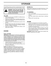
... OPERATION CHECK" in fuel, temperature, altitude or load. BELT REPLACEMENT • Install new forward (inside )V-belt from transmission pulley first and then from idler arm. • Remove reverse (outside groove of manual. OVERSPEEDING THE ENGINE ABOVE THE FACTORY HIGH SPEED SETTING CAN BE DANGEROUS. REVERSE IDLER PULLEY IDLER ARM PIN FORWARD MOTION (INSIDE) V-BELT REVERSE IDLER ARM REVERSE (OUTSIDE) V-BELT BELT GUARD BOLT ENGINE PULLEY BELT GUIDE FORWARD IDLER PULLEY FIG. 22 14 TRANSMISSION PULLEY Tighten securely. SERVICE AND ADJUSTMENTS FORWARD...
... OPERATION CHECK" in fuel, temperature, altitude or load. BELT REPLACEMENT • Install new forward (inside )V-belt from transmission pulley first and then from idler arm. • Remove reverse (outside groove of manual. OVERSPEEDING THE ENGINE ABOVE THE FACTORY HIGH SPEED SETTING CAN BE DANGEROUS. REVERSE IDLER PULLEY IDLER ARM PIN FORWARD MOTION (INSIDE) V-BELT REVERSE IDLER ARM REVERSE (OUTSIDE) V-BELT BELT GUARD BOLT ENGINE PULLEY BELT GUIDE FORWARD IDLER PULLEY FIG. 22 14 TRANSMISSION PULLEY Tighten securely. SERVICE AND ADJUSTMENTS FORWARD...
User Manual
Page 15
...; Pull starter handle slowly several times to distribute oil. • Replace with clean oil. (See "ENGINE" in the Maintenance section of the season or if the unit will cause your unit indoors and cover it run until the fuel lines and carburetor are securely fastened. TILLER • Clean entire tiller (See "CLEANING" in the Maintenance section of this manual). • Inspect and replace belts, if necessary (See belt replacement instructions in the Service and Adjustments section of this manual...
...; Pull starter handle slowly several times to distribute oil. • Replace with clean oil. (See "ENGINE" in the Maintenance section of the season or if the unit will cause your unit indoors and cover it run until the fuel lines and carburetor are securely fastened. TILLER • Clean entire tiller (See "CLEANING" in the Maintenance section of this manual). • Inspect and replace belts, if necessary (See belt replacement instructions in the Service and Adjustments section of this manual...
User Manual
Page 16
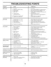
.... 3. Check oil level/change oil. 4. Remove and clean muffler. 5. Wheels and depth stake incorrectly adjusted. 1. Ground too wet. 1. Tine control is seated properly on plug. 6. Engine runs but tiller won't move 1. Throttle control not properly adjusted. 3. Engine not "CHOKED" properly. 3. Water in the Operation section. 3. Carburetor out of power 1. Fill fuel tank. 2. See "TO START ENGINE" in fuel. 6. Clean or replace air cleaner cartridge. 5. Make sure spark plug wire is not engaged. 2. Throttle control not set properly. 2. Replace spark plug or adjust gap...
.... 3. Check oil level/change oil. 4. Remove and clean muffler. 5. Wheels and depth stake incorrectly adjusted. 1. Ground too wet. 1. Tine control is seated properly on plug. 6. Engine runs but tiller won't move 1. Throttle control not properly adjusted. 3. Engine not "CHOKED" properly. 3. Water in the Operation section. 3. Carburetor out of power 1. Fill fuel tank. 2. See "TO START ENGINE" in fuel. 6. Clean or replace air cleaner cartridge. 5. Make sure spark plug wire is not engaged. 2. Throttle control not set properly. 2. Replace spark plug or adjust gap...

User Manual
Page 17
.... 5 KEY PART NO. REPAIR PARTS TILLER - - inches. 1 inch = 25.4 mm 17 NO. MODEL NUMBER PPFT55 (96081000700) HANDLE ASSEMBLY 3 1 16 2 3 4 5 6 10 28 11 14 44 7 8 9 19 21 29 18 20 43 12 13 handle_assy_34 KEY PART NO. NO. DESCRIPTION 14 532 40 51-09 Panel, Handle 16 532 16 63-77 Handle, R.H. 18 532 16 68-68 Cable, Control, Tine 19 532 15 12-29 Lever, Control, Tine 20...
.... 5 KEY PART NO. REPAIR PARTS TILLER - - inches. 1 inch = 25.4 mm 17 NO. MODEL NUMBER PPFT55 (96081000700) HANDLE ASSEMBLY 3 1 16 2 3 4 5 6 10 28 11 14 44 7 8 9 19 21 29 18 20 43 12 13 handle_assy_34 KEY PART NO. NO. DESCRIPTION 14 532 40 51-09 Panel, Handle 16 532 16 63-77 Handle, R.H. 18 532 16 68-68 Cable, Control, Tine 19 532 15 12-29 Lever, Control, Tine 20...

User Manual
Page 18
NO. REPAIR PARTS TILLER - - DESCRIPTION 1 532 18 03-77 Assembly, Bracket, Belt Guard 2 532 00 94-84 Clip, Cable 3 532 08 67-77 Screw, Hex, Washer Hd., Slotted, Thd. inches. 1 inch = 25.4 mm 18 DESCRIPTION 19 532 18 85-02 Bolt, Belt Guard 20 812 00 00-36 Ring, Klip 21 873 35 06-00 Nut, Hex, Jam 3/8-16 22 532 16 18-06 Pulley, Idler...
NO. REPAIR PARTS TILLER - - DESCRIPTION 1 532 18 03-77 Assembly, Bracket, Belt Guard 2 532 00 94-84 Clip, Cable 3 532 08 67-77 Screw, Hex, Washer Hd., Slotted, Thd. inches. 1 inch = 25.4 mm 18 DESCRIPTION 19 532 18 85-02 Bolt, Belt Guard 20 812 00 00-36 Ring, Klip 21 873 35 06-00 Nut, Hex, Jam 3/8-16 22 532 16 18-06 Pulley, Idler...

User Manual
Page 19
... Ga. 19 532 12 47-07 Bracket, Wheel 20 873 68 06-00 Locknut, Crown 3/8-16 21 874 76 05-16 Bolt, Hex 5/16-18 x 1 22 873 80 05-00 Locknut, w/insert 5/16-18 24 873 97 05-00 Nut Lock Hex Flange NOTE: All component dimensions given in U.S. DESCRIPTION 1 532 00 91-94 Pin,... Stake, R.H. 9 532 12 22-33 Stake, Depth 10 532 00 03-26 Pin, Clevis 11 874 78 06-28 Bolt, Hex, Fin 3/8-16 x 1-3/4 13 532 14 92-09 Support, Depth Stake, L.H. NO. NO. inches. 1 inch = 25.4 mm 19 MODEL NUMBER PPFT55 (96081000700) WHEEL AND DEPTH STAKE ASSEMBLY 1 23 7 9 6 8 13 10 2 16 21 20 24 18 17 19 18 20 ...
... Ga. 19 532 12 47-07 Bracket, Wheel 20 873 68 06-00 Locknut, Crown 3/8-16 21 874 76 05-16 Bolt, Hex 5/16-18 x 1 22 873 80 05-00 Locknut, w/insert 5/16-18 24 873 97 05-00 Nut Lock Hex Flange NOTE: All component dimensions given in U.S. DESCRIPTION 1 532 00 91-94 Pin,... Stake, R.H. 9 532 12 22-33 Stake, Depth 10 532 00 03-26 Pin, Clevis 11 874 78 06-28 Bolt, Hex, Fin 3/8-16 x 1-3/4 13 532 14 92-09 Support, Depth Stake, L.H. NO. NO. inches. 1 inch = 25.4 mm 19 MODEL NUMBER PPFT55 (96081000700) WHEEL AND DEPTH STAKE ASSEMBLY 1 23 7 9 6 8 13 10 2 16 21 20 24 18 17 19 18 20 ...

User Manual
Page 21
MODEL NUMBER PPFT55 (96081000700) TRANSMISSION 20 1 11 19 18 1716 11 7 10 12 KEY PART NO. inches. 1 inch = 25.4 mm 21 NO. DESCRIPTION 1 874 76 05-24 Bolt, Hex 5/16-18 x 1-1/2 Gr. 2 2 874 78 06-52 Bolt, Hex, Fin 3/8-16 x 3-1/4 3 819 13 13-11 Washer 13/32 x 13/16 x 11 5 873 90 06-00 Nut Lock Flg 3/8-16 unc...11 Shield, Tine 7 532 18 81-95 Bracket, Engine, R.H. 8 532 16 58-34 Bracket, Engine, L.H. 10 873 97 05-00 Nut Lock Hex Flg 11 532 18 79-12 Bolt, Shoulder 12 532 15 12-22 Transmission 2 3 5 6 8 14 10 14 10 transmission_12 KEY PART NO. DESCRIPTION 14 532 00 91-73 Spacer, Split...
MODEL NUMBER PPFT55 (96081000700) TRANSMISSION 20 1 11 19 18 1716 11 7 10 12 KEY PART NO. inches. 1 inch = 25.4 mm 21 NO. DESCRIPTION 1 874 76 05-24 Bolt, Hex 5/16-18 x 1-1/2 Gr. 2 2 874 78 06-52 Bolt, Hex, Fin 3/8-16 x 3-1/4 3 819 13 13-11 Washer 13/32 x 13/16 x 11 5 873 90 06-00 Nut Lock Flg 3/8-16 unc...11 Shield, Tine 7 532 18 81-95 Bracket, Engine, R.H. 8 532 16 58-34 Bracket, Engine, L.H. 10 873 97 05-00 Nut Lock Hex Flg 11 532 18 79-12 Bolt, Shoulder 12 532 15 12-22 Transmission 2 3 5 6 8 14 10 14 10 transmission_12 KEY PART NO. DESCRIPTION 14 532 00 91-73 Spacer, Split...
User Manual
Page 22
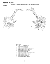
DESCRIPTION 1 532 40 36-53 Decal, Logo 2 532 40 37-13 Decal, Logo 3 532 15 73-78 Decal, HP, Reverse 4 532 18 99-36 Decal, Reverse, Tine Control 5 532 12 04-31 Decal, Hand Placement 6 532 40 36-89 Decal, Eng. MODEL NUMBER PPFT55 (96081000700) DECALS 1 3 2 54 6 7 8 11 9 12 10 KEY PART NO. REPAIR PARTS TILLER - - Dom 9 532 15 73-81 Decal, Hvy Duty 10 532 17 35-38 Decal, Rewind Intek 11 532 16 88-69 Decal, Tick Mark 12 532 12 00-75 Decal, Warning - - 532 40 36-61 Manual, Owner's 22 NO. Tiller 7 532 19 48-08 Decal, OHV. 8 532 16 22-15 Decal, Tine Shield Wrng.
DESCRIPTION 1 532 40 36-53 Decal, Logo 2 532 40 37-13 Decal, Logo 3 532 15 73-78 Decal, HP, Reverse 4 532 18 99-36 Decal, Reverse, Tine Control 5 532 12 04-31 Decal, Hand Placement 6 532 40 36-89 Decal, Eng. MODEL NUMBER PPFT55 (96081000700) DECALS 1 3 2 54 6 7 8 11 9 12 10 KEY PART NO. REPAIR PARTS TILLER - - Dom 9 532 15 73-81 Decal, Hvy Duty 10 532 17 35-38 Decal, Rewind Intek 11 532 16 88-69 Decal, Tick Mark 12 532 12 00-75 Decal, Warning - - 532 40 36-61 Manual, Owner's 22 NO. Tiller 7 532 19 48-08 Decal, OHV. 8 532 16 22-15 Decal, Tine Shield Wrng.


