
User Manual
Page 2
... fuel to vibrate abnormally, stop the engine (motor) and check immediately for the cause. (e) When practical, remove gas-powered equipment Vibration is for any repairs, adjustments or inspections. Training 1. Be thoroughly familiar with the controls and the proper use a nozzle lock-open device. (g) Replace gasoline cap securely and wipe up , transporting, adjusting or making any damage, and repair the damage before or trailer bed with electric drive motors or electric starting motors...
... fuel to vibrate abnormally, stop the engine (motor) and check immediately for the cause. (e) When practical, remove gas-powered equipment Vibration is for any repairs, adjustments or inspections. Training 1. Be thoroughly familiar with the controls and the proper use a nozzle lock-open device. (g) Replace gasoline cap securely and wipe up , transporting, adjusting or making any damage, and repair the damage before or trailer bed with electric drive motors or electric starting motors...
User Manual
Page 3
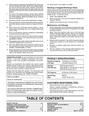
... of this owner's manual. Never operate the snow thrower without proper guards, and other bolts at too fast a rate. 12. Always use . 14. Disconnect the spark plug wire and keep a firm hold on the handles. To clear the chute: 1. TABLE OF CONTENTS SAFETY RULES 2-3 MAINTENANCE 14-15 PRODUCT SPECIFICATIONS 3 SERVICE AND ADJUSTMENTS 16-18 CUSTOMER RESPONSIBILITIES 3 STORAGE 19 ASSEMBLY / PRE-OPERATION 5-7 TROUBLESHOOTING 20 OPERATION 8-13 REPAIR PARTS 22-41 MAINTENANCE SCHEDULE 14 3 WARRANTY BACK COVER Run the...
... of this owner's manual. Never operate the snow thrower without proper guards, and other bolts at too fast a rate. 12. Always use . 14. Disconnect the spark plug wire and keep a firm hold on the handles. To clear the chute: 1. TABLE OF CONTENTS SAFETY RULES 2-3 MAINTENANCE 14-15 PRODUCT SPECIFICATIONS 3 SERVICE AND ADJUSTMENTS 16-18 CUSTOMER RESPONSIBILITIES 3 STORAGE 19 ASSEMBLY / PRE-OPERATION 5-7 TROUBLESHOOTING 20 OPERATION 8-13 REPAIR PARTS 22-41 MAINTENANCE SCHEDULE 14 3 WARRANTY BACK COVER Run the...
User Manual
Page 5
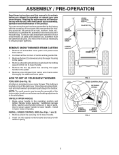
... toolbox. LOWER HANDLE FIG. 1 SPEED CONTROL ROD RETAINER SPRING SPEED CONTROL BRACKET SPEED CONTROL LEVER FIG. 2 5 HOW TO SET UP YOUR SNOW THROWER TOOL BOX (See Fig. 10) A toolbox is located on your new snow thrower. NOTE: The multi-wrench may be tightened securely. INSTALL SPEED CONTROL ROD (See Figs. 1 and 2) 1. Remove the two (2) screws securing the auger housing to lower handle. UPPER HANDLE HANDLE KNOB SPEED CONTROL ROD PLASTIC TIE REMOVE SNOW THROWER FROM CARTON 1. ASSEMBLY / PRE-OPERATION Read these instructions and this manual in its...
... toolbox. LOWER HANDLE FIG. 1 SPEED CONTROL ROD RETAINER SPRING SPEED CONTROL BRACKET SPEED CONTROL LEVER FIG. 2 5 HOW TO SET UP YOUR SNOW THROWER TOOL BOX (See Fig. 10) A toolbox is located on your new snow thrower. NOTE: The multi-wrench may be tightened securely. INSTALL SPEED CONTROL ROD (See Figs. 1 and 2) 1. Remove the two (2) screws securing the auger housing to lower handle. UPPER HANDLE HANDLE KNOB SPEED CONTROL ROD PLASTIC TIE REMOVE SNOW THROWER FROM CARTON 1. ASSEMBLY / PRE-OPERATION Read these instructions and this manual in its...
User Manual
Page 6
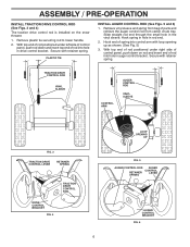
... top end of parts and retrieve the auger control rod from bag of rod into hole in auger control bracket. TRACTION DRIVE CONTROL ROD VINYL SLEEVE CONTROL ARM AUGER CONTROL ROD VINYL SLEEVE FIG. 3 TRACTION DRIVE CONTROL LEVER RETAINER SPRING TRACTION DRIVE CONTROL ROD DRIVE CONTROL BRACKET FIG. 4 6 LOOP OPENING UP FIG. 5 AUGER CONTROL ROD AUGER CONTROL RETAINER LEVER SPRING AUGER CONTROL BRACKET FIG. 6 ASSEMBLY / PRE-OPERATION INSTALL TRACTION DRIVE CONTROL ROD (See Figs. 3 and 4) The traction drive control rod is installed on rod...
... top end of parts and retrieve the auger control rod from bag of rod into hole in auger control bracket. TRACTION DRIVE CONTROL ROD VINYL SLEEVE CONTROL ARM AUGER CONTROL ROD VINYL SLEEVE FIG. 3 TRACTION DRIVE CONTROL LEVER RETAINER SPRING TRACTION DRIVE CONTROL ROD DRIVE CONTROL BRACKET FIG. 4 6 LOOP OPENING UP FIG. 5 AUGER CONTROL ROD AUGER CONTROL RETAINER LEVER SPRING AUGER CONTROL BRACKET FIG. 6 ASSEMBLY / PRE-OPERATION INSTALL TRACTION DRIVE CONTROL ROD (See Figs. 3 and 4) The traction drive control rod is installed on rod...
User Manual
Page 7
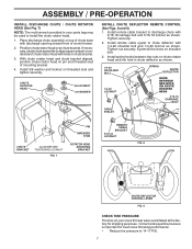
... chute rotator head and chute bracket aligned, position chute rotator head on top of chute base with holes in chute deflector as shown. 1/4-20 SHOULDER BOLT 1/4-20 LOCKNUT SPRING CHUTE DEFLECTOR HOOK BETWEEN HEX NUTS ON CHUTE ROTATER HEAD 5/16-18 CARRIAGE BOLT CABLE EYELET CHUTE BRACKET ALIGN BEFORE TIGHTENING LOCKNUT FIG. 7 PIN THREADED STUD ROTATOR HEAD MOUNTING BRACKET REMOTE CABLE BRACKET 5/16-18 LOCKNUT FIG. 8 CHUTE DEFLECTOR CONTROL LEVER FIG. 9 CHECK TIRE PRESSURE The...
... chute rotator head and chute bracket aligned, position chute rotator head on top of chute base with holes in chute deflector as shown. 1/4-20 SHOULDER BOLT 1/4-20 LOCKNUT SPRING CHUTE DEFLECTOR HOOK BETWEEN HEX NUTS ON CHUTE ROTATER HEAD 5/16-18 CARRIAGE BOLT CABLE EYELET CHUTE BRACKET ALIGN BEFORE TIGHTENING LOCKNUT FIG. 7 PIN THREADED STUD ROTATOR HEAD MOUNTING BRACKET REMOTE CABLE BRACKET 5/16-18 LOCKNUT FIG. 8 CHUTE DEFLECTOR CONTROL LEVER FIG. 9 CHECK TIRE PRESSURE The...
User Manual
Page 9
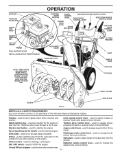
...or reverse motion and speed of snow thrower. Choke control - Discharge chute control lever - Remove when snow thrower is thrown. used to STOP the engine. MUFFLER GASOLINE FILLER CAP CHOKE CONTROL SAFETY IGNITION KEY ON / OFF SWITCH PRIMER FUEL SHUT-OFF VALVE RECOIL (AUXILIARY) STARTER HANDLE OPERATION ELECTRIC AUGER DISCHARGE CHUTE CONTROL LEVER START CONTROL BUTTON LEVER DRIVE SPEED CONTROL LEVER DEFLECTOR REMOTE CONTROL LEVER POWER CORD PLUG CHUTE DEFLECTOR TRACTION DRIVE CONTROL LEVER DISCHARGE CHUTE CLEAN-OUT TOOL LH TURN TRIGGER LIGHT HANDLE KNOB NOTE: ITEMS...
...or reverse motion and speed of snow thrower. Choke control - Discharge chute control lever - Remove when snow thrower is thrown. used to STOP the engine. MUFFLER GASOLINE FILLER CAP CHOKE CONTROL SAFETY IGNITION KEY ON / OFF SWITCH PRIMER FUEL SHUT-OFF VALVE RECOIL (AUXILIARY) STARTER HANDLE OPERATION ELECTRIC AUGER DISCHARGE CHUTE CONTROL LEVER START CONTROL BUTTON LEVER DRIVE SPEED CONTROL LEVER DEFLECTOR REMOTE CONTROL LEVER POWER CORD PLUG CHUTE DEFLECTOR TRACTION DRIVE CONTROL LEVER DISCHARGE CHUTE CLEAN-OUT TOOL LH TURN TRIGGER LIGHT HANDLE KNOB NOTE: ITEMS...
User Manual
Page 10
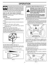
... throwing snow. Use the choke control whenever you are starting a cold engine. AUGER CONTROL LEVER FIG. 12 10 FIG. 14 AUGER • Release the auger control lever to stop throwing snow. OPERATION The operation of any adjustments or repairs. Always operate the snow thrower with the fuel shut-off valve is controlled by the position of all persons, small children and pets at all controls before adding fuel or attempting to stop engine. STOPPING TRACTION DRIVE • Release traction drive control lever...
... throwing snow. Use the choke control whenever you are starting a cold engine. AUGER CONTROL LEVER FIG. 12 10 FIG. 14 AUGER • Release the auger control lever to stop throwing snow. OPERATION The operation of any adjustments or repairs. Always operate the snow thrower with the fuel shut-off valve is controlled by the position of all persons, small children and pets at all controls before adding fuel or attempting to stop engine. STOPPING TRACTION DRIVE • Release traction drive control lever...
User Manual
Page 11
... the engine, then squeeze the auger control lever to the handle to clear snow from it to adjust the skid plates. Grasp the tool firmly by the traction drive control lever located on the speed control lever and move speed control lever when traction drive control lever is engaged. After the packed snow has been dislodged, return the cleanout tool to dislodge the blockage. Be sure lever springs back and locks into desired position. OPERATION USING THE CLEAN-OUT TOOL (See...
... the engine, then squeeze the auger control lever to the handle to clear snow from it to adjust the skid plates. Grasp the tool firmly by the traction drive control lever located on the speed control lever and move speed control lever when traction drive control lever is engaged. After the packed snow has been dislodged, return the cleanout tool to dislodge the blockage. Be sure lever springs back and locks into desired position. OPERATION USING THE CLEAN-OUT TOOL (See...
User Manual
Page 12
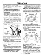
... are adjusted to lowest (highest scraper clearance) position. 1. WARNING: Wipe off engine and wait for opposite side of the snow thrower. • Loosen upper adjustment nut enough to allow drift cutter to be reversed, providing additional service before storage of 87 octane. ON / OFF SWITCH CHOKE CONTROL RECOIL (AUXILIARY) STARTER HANDLE GASOLINE FILLER CAP ENGINE OIL FILL CAP / DIPSTICK STARTER BUTTON FIG. 19 ADJUSTMENT NUT SAFETY IGNITION KEY PRIMER FUEL SHUT-OFF VALVE POWER CORD PLUG NOTE...
... are adjusted to lowest (highest scraper clearance) position. 1. WARNING: Wipe off engine and wait for opposite side of the snow thrower. • Loosen upper adjustment nut enough to allow drift cutter to be reversed, providing additional service before storage of 87 octane. ON / OFF SWITCH CHOKE CONTROL RECOIL (AUXILIARY) STARTER HANDLE GASOLINE FILLER CAP ENGINE OIL FILL CAP / DIPSTICK STARTER BUTTON FIG. 19 ADJUSTMENT NUT SAFETY IGNITION KEY PRIMER FUEL SHUT-OFF VALVE POWER CORD PLUG NOTE...
User Manual
Page 13
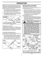
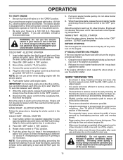
... the primer. SNOW THROWING TIPS • Go slower in "ON" position. 3. OPERATION TO START ENGINE • Be sure fuel shut-off valve is equipped with both a 120 Volt A.C. Your snow thrower engine is in parts bag) into a three-hole grounded 120 Volt A.C. electric starter and a recoil starter. The electric starter is equipped with a three-wire power cord and plug and is not a 120 Volt A.C. household current. • Be sure your house is...
... the primer. SNOW THROWING TIPS • Go slower in "ON" position. 3. OPERATION TO START ENGINE • Be sure fuel shut-off valve is equipped with both a 120 Volt A.C. Your snow thrower engine is in parts bag) into a three-hole grounded 120 Volt A.C. electric starter and a recoil starter. The electric starter is equipped with a three-wire power cord and plug and is not a 120 Volt A.C. household current. • Be sure your house is...
User Manual
Page 14
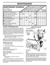
... manual. All adjustments in this manual). LUBRICATION CHART SAE 5W-30 Motor Oil See "ENGINE" in both tires (14-17 P.S.I.). • Keep tires free of gasoline and oil, which can harm rubber. Check for deterioration and wear after every 50 hours maintenance. Replace belts if they are functioning properly. A new spark plug will need to be made periodically to slip from wear. (See "TO REMOVE BELT COVER" in this manual...
... manual. All adjustments in this manual). LUBRICATION CHART SAE 5W-30 Motor Oil See "ENGINE" in both tires (14-17 P.S.I.). • Keep tires free of gasoline and oil, which can harm rubber. Check for deterioration and wear after every 50 hours maintenance. Replace belts if they are functioning properly. A new spark plug will need to be made periodically to slip from wear. (See "TO REMOVE BELT COVER" in this manual...
User Manual
Page 15
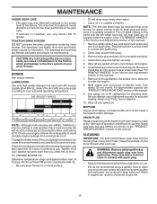
... your snow thrower unless the electrical system, muffler and carburetor are covered to the oil drain plug and placement of this manual. Check your snow thrower. NOTE: The left wheel (if removed for accurate reading. The unit tilted, resting on dipstick. 10. Clean area around drain plug. 3. Do not overfill. Check the crankcase oil level before next oil change. Remove safety ignition key and disconnect spark plug wire from spark plug. Spark plug type and gap setting are lifetime lubricated and require no lubrication. Refill engine...
... your snow thrower unless the electrical system, muffler and carburetor are covered to the oil drain plug and placement of this manual. Check your snow thrower. NOTE: The left wheel (if removed for accurate reading. The unit tilted, resting on dipstick. 10. Clean area around drain plug. 3. Do not overfill. Check the crankcase oil level before next oil change. Remove safety ignition key and disconnect spark plug wire from spark plug. Spark plug type and gap setting are lifetime lubricated and require no lubrication. Refill engine...
User Manual
Page 16
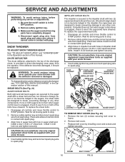
...; Replace belt cover by installing cover and screws and tighten securely. WARNING: To avoid serious injury, never operate your snow thrower with the deflector removed or damaged. • To change direction and/or distance snow is secured to the auger shaft with your snow thrower. 4. To replace the shear bolts: 1. Place wire where it should be replaced. Insert safety ignition key and reconnect spark plug wire to frame. 2. Insert safety ignition key and reconnect spark plug wire to STOP position. SERVICE...
...; Replace belt cover by installing cover and screws and tighten securely. WARNING: To avoid serious injury, never operate your snow thrower with the deflector removed or damaged. • To change direction and/or distance snow is secured to the auger shaft with your snow thrower. 4. To replace the shear bolts: 1. Place wire where it should be replaced. Insert safety ignition key and reconnect spark plug wire to frame. 2. Insert safety ignition key and reconnect spark plug wire to STOP position. SERVICE...
User Manual
Page 17
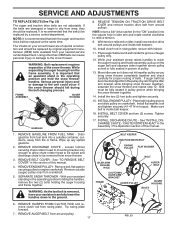
... REMOVE BELT COVER" in the operating position holding the handles, remove the two (2) bolts holding the auger housing and frame together. With your nearest service center/department. REMOVE AUGER BELT from the pulley (by catching the idler arm bracket while bringing snow thrower together), separate the snow thrower and repeat step 12. If the belts are not adjustable. WARNING: Belt replacement requires separation of this manual. 4. FRAME ASSEMBLY AUGER HOUSING HANDLES 8. See "INSTALL DISCHARGE CHUTE / CHUTE ROTATER HEAD" in swing plate; REMOVE ENGINE PULLEY - SEPARATE SNOW...
... REMOVE BELT COVER" in the operating position holding the handles, remove the two (2) bolts holding the auger housing and frame together. With your nearest service center/department. REMOVE AUGER BELT from the pulley (by catching the idler arm bracket while bringing snow thrower together), separate the snow thrower and repeat step 12. If the belts are not adjustable. WARNING: Belt replacement requires separation of this manual. 4. FRAME ASSEMBLY AUGER HOUSING HANDLES 8. See "INSTALL DISCHARGE CHUTE / CHUTE ROTATER HEAD" in swing plate; REMOVE ENGINE PULLEY - SEPARATE SNOW...
User Manual
Page 18
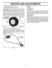
... and turn buckle, located on the right hand cable. SERVICE AND ADJUSTMENTS TO REMOVE WHEELS (See Fig. 24) • Remove the klik pin and remove wheel from your local parts dealer. Overspeeding the engine above the factory high speed setting can be sure to use the hole in wheel hub are not used for proper engine speed. If you think the engine-governed high speed needs adjusting, contact a service center/department, which is factory set for your model snow thrower. WHEEL WHEEL HUB...
... and turn buckle, located on the right hand cable. SERVICE AND ADJUSTMENTS TO REMOVE WHEELS (See Fig. 24) • Remove the klik pin and remove wheel from your local parts dealer. Overspeeding the engine above the factory high speed setting can be sure to use the hole in wheel hub are not used for proper engine speed. If you think the engine-governed high speed needs adjusting, contact a service center/department, which is factory set for your model snow thrower. WHEEL WHEEL HUB...
User Manual
Page 19
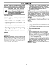
... Service and Adjustments section of oil through spark plug hole into cylinder. 3. Add stabilizer to distribute oil. 4. ENGINE OIL Drain oil (with engine warm) and replace with new spark plug. Pull recoil starter handle slowly a few times to gasoline in fuel tank or storage container. store it from one ounce (29 ml) of this manual). Inspect and replace belts, if necessary (See "TO REPLACE BELTS" in a clean, dry area. 1. Be sure that does not retain moisture. ENGINE See engine manual. Run engine...
... Service and Adjustments section of oil through spark plug hole into cylinder. 3. Add stabilizer to distribute oil. 4. ENGINE OIL Drain oil (with engine warm) and replace with new spark plug. Pull recoil starter handle slowly a few times to gasoline in fuel tank or storage container. store it from one ounce (29 ml) of this manual). Inspect and replace belts, if necessary (See "TO REPLACE BELTS" in a clean, dry area. 1. Be sure that does not retain moisture. ENGINE See engine manual. Run engine...
User Manual
Page 20
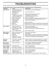
... belt is flooded. 8. Check / reinstall auger belt. 2. Choke in fuel. 1. Turn fuel shut-off valve (if so equipped) in OFF position. 2. Move to ON position). 5. Connect wire to OFF position. 2. Replace spark plug. 10. Empty fuel tank & carburetor, refill with fresh, clean gasoline. 5. Remove ice and snow on and around fuel tank cap. 4. Choke is in FULL position. 2. Carburetor is in need of pulley. 2. See "IF RECOIL STARTER HAS FROZEN" in STOP position (or ON/OFF switch is covered with fresh, clean gasoline. 4. Clean snow chute. 4. Throttle in the Operation...
... belt is flooded. 8. Check / reinstall auger belt. 2. Choke in fuel. 1. Turn fuel shut-off valve (if so equipped) in OFF position. 2. Move to ON position). 5. Connect wire to OFF position. 2. Replace spark plug. 10. Empty fuel tank & carburetor, refill with fresh, clean gasoline. 5. Remove ice and snow on and around fuel tank cap. 4. Choke is in FULL position. 2. Carburetor is in need of pulley. 2. See "IF RECOIL STARTER HAS FROZEN" in STOP position (or ON/OFF switch is covered with fresh, clean gasoline. 4. Clean snow chute. 4. Throttle in the Operation...
User Manual
Page 24
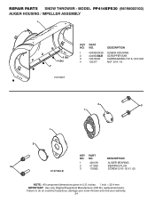
REPAIR PARTS SNOW THROWER - DESCRIPTION 1 420478 AUGER BEARING 3 2 411939 BEARING PLUG 3 179582 SCREW 5/16−18 X 1.00 01.07.024-B NOTE: All component dimensions given in U.S. inches. 1 inch = 25.4 mm IMPORTANT: Use only Original Equipment Manufacturer (O.E.M.) replacement parts. MODEL PP414EPS30 (96198003102) AUGER HOUSING / IMPELLER ASSEMBLY 1 3 (5x) 4 (5x) 2 01.07.003-A KEY NO. 1 2 3 4 PART NO. 404930X428 404933X431 72270505 155377 DESCRIPTION AUGER HOUSING SCRAPPER BAR CARRIAGE BOLT 5/16−18 X .625 NUT 5/16−18 2 3 1 1 2 KEY...
REPAIR PARTS SNOW THROWER - DESCRIPTION 1 420478 AUGER BEARING 3 2 411939 BEARING PLUG 3 179582 SCREW 5/16−18 X 1.00 01.07.024-B NOTE: All component dimensions given in U.S. inches. 1 inch = 25.4 mm IMPORTANT: Use only Original Equipment Manufacturer (O.E.M.) replacement parts. MODEL PP414EPS30 (96198003102) AUGER HOUSING / IMPELLER ASSEMBLY 1 3 (5x) 4 (5x) 2 01.07.003-A KEY NO. 1 2 3 4 PART NO. 404930X428 404933X431 72270505 155377 DESCRIPTION AUGER HOUSING SCRAPPER BAR CARRIAGE BOLT 5/16−18 X .625 NUT 5/16−18 2 3 1 1 2 KEY...
User Manual
Page 28
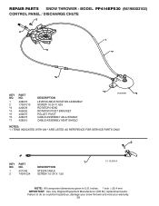
... U.S. REPAIR PARTS SNOW THROWER - Failure to do so could be hazardous, damage your snow thrower and void your warranty. 28 MODEL PP414EPS30 (96198003102) CONTROL PANEL / DISCHARGE CHUTE 2 2 *3 1 *7 *6 KEY NO. 1 2 *3 *4 *5 *6 *7 PART NO. 428272 17501010 420678 405932 420675 428273 428310 DESCRIPTION LEVER/CABLE ROTATOR ASSEMBLY SCREW 10-24 X .625 ROTATOR HEAD ROTATOR PIVOT BRACKET PULLEY PIVOT CABLE ASSEMBLY ADJUSTABLE CABLE ASSEMBLY HEAT SHIELD *4 01.09.010-B *5 NOTES: 1. ITEMS INDICATED WITH AN * ARE LISTED AS REFERENCE FOR SERVICE PARTS...
... U.S. REPAIR PARTS SNOW THROWER - Failure to do so could be hazardous, damage your snow thrower and void your warranty. 28 MODEL PP414EPS30 (96198003102) CONTROL PANEL / DISCHARGE CHUTE 2 2 *3 1 *7 *6 KEY NO. 1 2 *3 *4 *5 *6 *7 PART NO. 428272 17501010 420678 405932 420675 428273 428310 DESCRIPTION LEVER/CABLE ROTATOR ASSEMBLY SCREW 10-24 X .625 ROTATOR HEAD ROTATOR PIVOT BRACKET PULLEY PIVOT CABLE ASSEMBLY ADJUSTABLE CABLE ASSEMBLY HEAT SHIELD *4 01.09.010-B *5 NOTES: 1. ITEMS INDICATED WITH AN * ARE LISTED AS REFERENCE FOR SERVICE PARTS...
User Manual
Page 44
... products which we will exchange the Battery, charging you have any power equipment unit or attachment are belts, blades, blade adapters, normal wear, normal adjustments, standard hardware and normal maintenance. 7. In the event you 1/12 of the price of a new Battery for the movement of the authorized dealer from the date of 1975. THIS WARRANTY DOES NOT APPLY TO INCIDENTAL OR...
... products which we will exchange the Battery, charging you have any power equipment unit or attachment are belts, blades, blade adapters, normal wear, normal adjustments, standard hardware and normal maintenance. 7. In the event you 1/12 of the price of a new Battery for the movement of the authorized dealer from the date of 1975. THIS WARRANTY DOES NOT APPLY TO INCIDENTAL OR...


